Advertisement
Quick Links
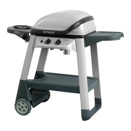
Excel 300T Gas BBQ
Assembly Instructions
246124
- Please keep for future reference
Dimensions
Width - 119.6cm
Depth - 55.6cm
Height - 102.3cm
Important
– Please read the instructions before using the appliance
If you need help or have damaged or missing parts, call the Customer Helpline:
08450 778888 (Homebase) / 08456 400800 (Argos)
Issue 2 - 21/11/12
Advertisement

Summary of Contents for HOME RETAIL GROUP Excel 300T
- Page 1 Excel 300T Gas BBQ Assembly Instructions 246124 - Please keep for future reference Dimensions Width - 119.6cm Depth - 55.6cm Height - 102.3cm Important – Please read the instructions before using the appliance If you need help or have damaged or missing parts, call the Customer Helpline:...
- Page 2 Safety and Care Advice Important Information • Retain these instructions for future reference. • This product is for outdoor use only. Do not use indoors. • Do not use the barbecue or store gas bottles below ground level. LP gas is heavier than air so if a leak occurs the gas will collect at a low level and could ignite in the presence of a flame or spark.
- Page 3 Safety and Care Advice WILL INVALIDATE ANY WARRANTY. Please consult your local gas dealer for the most suitable gas bottles and regulators. Installation Selecting a Location This barbecue is for outdoor use only and should be placed in a well-ventilated area, and on a safe and even surface.
- Page 4 Safety and Care Advice Lighting the Barbecue • Open the barbecue hood or lid before lighting. Never light your barbecue with the hood or lid closed. • Ensure all knobs are in the off position. Open the gas control valve on the gas bottle or regulator. •...
- Page 5 Safety and Care Advice barbecue. If the internal heat becomes too high, turn the burners down to the low position. It is not necessary or advisable to have all of the burners on high when the hood is closed. DO NOT ALLOW YOUR BARBECUE TO OVERHEAT. Take care when opening the hood as hot steam can be released on opening.
- Page 6 Safety and Care Advice Care and Maintenance Regularly clean your barbecue between uses and especially after extended periods of storage. Ensure the barbecue and its components are suffi ciently cool before cleaning. Do not leave the barbecue exposed to outside weather conditions or stored in damp, moist areas. •...
- Page 7 Safety and Care Advice venturi tubes, taking care not to enlarge the portholes. Clean the insect screen on the end of the venturi tube with a bristle brush (i.e. an old toothbrush). You may need a torch to see into the venturi tube to make sure it is clear. Turn the burner up on end and lightly tap against a hard surface like a piece of wood, to dislodge any debris from inside.
- Page 8 If you have damaged or missing components, Components - Panels call the Customer Helpline: 08450 778888 (Homebase) / 08456 400800 (Argos). Please check you have all the panels listed below Hood and Body Assembly x1 Hood Handle x1 Warming Rack x1 Cooking Grill x1 Lava Rock x1 Main Burner x1...
- Page 9 Components - Panels Please check you have all the panels listed below Side Shelf Bracket A x1 Side Shelf Bracket B x1 Side Burner Shelf x1 Side Burner Grid x1 Side Burner x1 Side Burner Electrode x1 Side Burner Knob x1 Fixing Support x2 Hose Clip x1 Left Front Leg x1...
- Page 10 Components - Panels Please check you have all the panels listed below Right Rear Leg x1 Leg End Loop x1 Right Front Leg x1 Bottom Shelf x1 Axle x1 Wheel Spacer x2 Wheel x2...
- Page 11 Components - Fittings Please check you have all the fi ttings listed below Note: The quantities below are the correct amount to complete the assembly. In some cases more fi ttings may be supplied than are required. ST4.0x10 Screw x3 ST4.0x15 Screw x4 ST4.8x15 Screw x2 M4x10 Bolt x1...
- Page 12 Assembly Instructions Step 1 Attach right front leg and right rear leg leg end loop . The legs are a push fi t onto the leg end loop.In case of diffi culty, they may need tapping with a soft faced mallet. Take care not to damage the parts.
- Page 13 Assembly Instructions Step 3 Attach bottom shelf the gas hottle holder using ST4.8x15 screws . Take care not to over tighten these screws which will damage the plastic gas bottle holder. Step 4 Install bottom shelf between right front leg and right rear leg using M6x15 bolts FRONT...
- Page 14 Assembly Instructions Step 5 Thread axle through the clamping brackets underneath the gas bottle holder and tighten the clamping screws. Take care not to over tighten these screws which will damage the plastic gas bottle holder. Slide a wheel spacer over each end of the axle.
- Page 15 Assembly Instructions Step 7 Attach hood handle onto hood and body assembly using the M5x10 bolts NOTE: Please fi x the right side fi rst. Step 8 Carefully place the hood and body assembly onto the tops of the legs. Ensure the four supports underneath the body fi...
- Page 16 Assembly Instructions Step 9 Attach the control panel assembly to left front and right front leg using the M6x15 bolts Step 10 Thread the grease cup holder through the guide hole in barbecue body. Insert the grease onto the grease cup holder.
- Page 17 Assembly Instructions Step 11 Remove the retianing nut from main electrode assembly Insert the main electrode into the hole at the bottom of the barbecue body and secure with the retaining nut. Connect main electrode wire onto the end of ignition button under the control panel.
- Page 18 Assembly Instructions Step 12 Place main burner into barbecue body. Ensure that the burner venturi tubes are over the ends of the gas valves. They are a loose fi t and not a gas tight seal. Secure the burner with ST4.0x10 screws from underside.
- Page 19 Assembly Instructions Step 14 Remove the plastic wrap from lava rock . Lay the lava rock into the barbecue body, ensuring it lies level within the body. Step 15 Lay the cooking grill into place, ensuring it lies level within the body.
- Page 20 Assembly Instructions Step 16 Attach warming rack to the hood and barbecue body as shown. Make sure that the swing legs fi x to the body of the barbecue and the shorter fi xed legs go through the holes in the hood.
- Page 21 Assembly Instructions Step 18 Slide a shelf spacer onto a M6x15 bolt and screw it into the upper fi xing point on right rear leg as shown. Repeat for right front leg Attach the assembled side shelf to the right hand side of the barbecue by sliding a shelf spacer onto a...
- Page 22 Assembly Instructions Step 19 Attach the side burner shelf to the left front and left rear leg using M6x15 bolts Step 20 Unscrew retaining bolts from side burner valve, fi x the side burner valve onto side burner shelf using the retaining bolts.
- Page 23 Assembly Instructions Step 21 Install side burner knob onto the side burner valve. Step 22 Place the side burner electrode onto side burner shelf as shown. Continued on next page...
- Page 24 Assembly Instructions Step 22 - continued Place side burner through the central hole in side burner shelf bottom. Make sure the side burner venturi tube fi t over the side burner valve gas outlet. This is a loose fi t and not a gas tight seal.
- Page 25 Assembly Instructions Step 23 Place the side burner grid onto the side burner shelf. NOTE: Do not use any cooking utensils (pots, pans etc.) with a diameter of over 280mm on the side burner. Always keep the utensils in the centre of the side burner.
-
Page 26: Technical Specifications
0.71mm LPG mixture: 37 mbar 0.69mm LPG mixture: 50 mbar Gas Consumption: Excel 300T: 446g/h Side Burner: 165g/h Countries of Use: BE, CH, CY, CZ, ES, FR, GB, GR, IE, IT, LT, LU, LV, PT, SK, SI 3+(28-30/37) BE, CY, DK, EE, FI, FR, HU, IT, LT, NL, NO, SE, SI, SK, RO, HR, TR, BG, IS, LU, MT... -
Page 27: Troubleshooting
Troubleshooting Problem Possible Cause Solution Burner will not light using the LP gas bottle is empty Replace with full bottle ignition system Faulty regulator Have regulator checked or replaced Obstructions in burner Clean burner Obstructions in gas jets or gas Clean jets and gas hose hose Electrode or ignition button wire is...
Need help?
Do you have a question about the Excel 300T and is the answer not in the manual?
Questions and answers