Table of Contents
Advertisement
Quick Links
Advertisement
Table of Contents

Summary of Contents for HygroMatik VN
- Page 1 Manual Atomising Vacuum Nozzle System...
- Page 2 Maintenance work can be reduced by using fully demineralised water. Consult your HygroMatik specialists. We will answer any questions you may have concerning water and advise you on the installation and initial operation of your HygroMatik atomising sys- tem. Copyright HygroMatik GmbH VN e October 2011 Information in this manual is subject to change or alteration without prior notice.
-
Page 3: Table Of Contents
4. Operation and Installation..................12 4.1 Basic Requirements ....................12 4.2 Sequence of Operation ....................12 4.3 Vacuum Nozzle Type VN ................... 13 4.3.1 Vacuum Nozzle ....................... 13 4.3.2 Vacuum Nozzle Technical Specifications ............... 14 4.4 Control Unit Type CU-1....................15 4.4.1 Operation with hygrostat .................. - Page 4 7.1 Installing the Compressed Air Connection..............40 8. Electrical Installation....................41 8.1 Electrical Installation ....................41 8.2 Checklist Prior to Initial Operation ................41 8.3 Wiring Diagram ......................42 9. Maintenance ....................... 43 9.1 Maintenance and Maintenance Checks..............43 9.2 Maintenance Checks and Adjustments ..............43 9.3 Cleaning and Maintenance ..................
-
Page 5: Introduction
They will impress you with their safety, ease of use and econo- mical operation. In order to operate your HygroMatik nozzle system safely, pro- perly and efficiently, please read these operation instructions. Employ your nozzle system only in sound condition and as directed. - Page 6 To achieve breathable air quality, an extra filter is required. HygroMatik vacuum nozzles operate with drinking water. Fully demineralised water must be used to prevent calcium and mine- ral dust. Usage of fully demineralised water also lengthens main- tenance intervals.
-
Page 7: Typographic Distinctions
If the product is resold, turn the documenta- tion over to the new operator. If the documentation is lost, please contact HygroMatik. Versions in Other Languages These operating instructions are available in several languages. If interested, please contact HygroMatik or your HygroMatik dea- ler. Page 7... -
Page 8: Safety Notes
2. Safety Notes 2.1 Overview These safety notes are required by law. They promote work- place safety and accident prevention. Warnings and Safety Symbols The safety symbols below identify sections containing warnings about hazards or potential dangers. Please familiarize yourself with these symbols. -
Page 9: Guidelines For Safe Operation
2.2 Guidelines for Safe Operation Overview Observe all safety information and warnings which appear on the nozzle system. In case of a malfunction, switch off the nozzle system immedia- tely and prevent a restart. Repair malfunctions promptly. After any repair work, have qualified personnel check the safe operation of the nozzle system. -
Page 10: Disposal After Dismantling
Electrical Warning: Work on the electrical system must be performed by qualified personnel. If the electrical power supply malfunctions, switch off the control unit immediately. Use only original fuses with the appropriate amperage rating. Regularly check the control unit's electrical equipment. Promptly repair any faults, such as loose connections or damaged wiring. -
Page 11: Transport
3. Transport 3.1 General information Note: Take care when transporting the HygroMatik vacuum nozzle system to prevent the device and packaging from being damaged by impact or accidental loading or unloading. 3.2 Packaging Note: Notice the symbols affixed to the packing box. -
Page 12: Operation And Installation
4. Operation and Installation Basic Requirements For basic operational requirements of the HygroMatik nozzle system, please read Section “Directions for Use”. 4.2 Sequence of Operation When the hygrostat calls for an increase in humidity, the control unit opens the pilot and vacuum valves by means of control air. -
Page 13: Vacuum Nozzle Type Vn
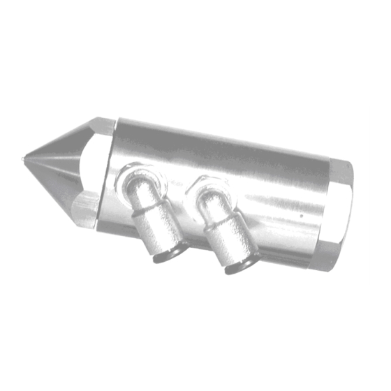
4.3 Vacuum Nozzle Type VN All water-bearing parts of the vacuum nozzle Type VN are made of stainless steel. The pilot valve supplies the nozzles with atomisation air. The vacuum valve feeds the nozzles with water. The control unit con- trols both valves via a control air line. -
Page 14: Vacuum Nozzle Technical Specifications
[l/min] 50,0 max.* sound level at a distance [dB(A)] 69,5 of 1m** at 8 bar atomisation pressure and 0.1 bar at the vacuum valve **: at 5 bar atomisation pressure sectional drawing vacuum nozzle Type VN Page 14... -
Page 15: Control Unit Type Cu-1
The CU-1 control unit switches the vacuum nozzles on and off according to humidification requirements. It also ensures that that VN nozzle cleaning cycles are performed at regular inter- vals. The following control unit is available with the vacuum nozzles:... -
Page 16: Operation With Hygrostat
4.4.2 VN Nozzle Self-Cleaning Self-cleaning takes place in regular cycles. The control unit briefly switches off the pressure to the control air line (3). The pilot and vacuum valves shut off the air and water supply to the nozzles.The springs in the nozzles relax and push back the pis-... -
Page 17: Operation And Display
The factory settings for the cleaning interval and the duration of the cleaning cycle are: Cleaning cleaning interval 20 min duration of cleaning 5 sec. 4.4.3 Operation and Display Control Unit Type CU-1 » Turn on the control unit using switch (7). The green "power" LED lights up and the nozzle system is ready for operation. -
Page 18: Setting The Cleaning Interval
When humidification is needed the display shows the following message: The system air pressure is adjusted on the valve (9) and is indi- cated by the manometer (8). Note: Set the atomisation output level as specified in Section “Output Table” 4.4.4 Setting the Cleaning Interval The cleaning interval and the duration of cleaning are set ex works to:... -
Page 19: Control Unit Technical Specifications
4.4.5 Control Unit Technical Specifications Control Unit Type CU-1 compressed air [mm] 6/4 supply max. 10 Connections: outer / inner diameter control air for [mm] 6/4 Pilotvalve and Vacuumvalve installation area [%RH 30 - 90 dimensions HxWxD [mm] 250x296x107 weight [kg] power supply connection 230V/1Ph/50Hz... -
Page 20: Pilot Valve Type Pv
4.5 Pilot Valve Type PV As soon as the control unit activates the pilot valve using the control air line (2), the pilot valve brings the atomisation air pres- sure for the nozzles to the control air pressure set by the control unit. -
Page 21: Pilot Valve Technical Specifications
4.5.2 Pilot Valve Technical Specifications Pilot Valve compressed air supply 10/8 mm control line from the control 6/4 mm Connections: outer / unit inner diameter atomisation air to the nozz- 2 x 10/8 mm dimensions HxWxD 65 x 65 x 65 mm approved for use with max. - Page 22 Cross section:Vacuum Valve Type VV8 Location Designation control air connection water inlet connection connection, water outlet to the nozzles manometer pressure reduction valve valve cone, water outlet valve plate, water outlet diaphragm, water outlet valve spring, water outlet valve spring, water inlet valve cone, water inlet valve plate, water inlet diaphragm, water inlet...
-
Page 23: Vacuum Valve Mode Of Operation
4.6.1 Vacuum Valve Mode of Operation The water supply is connected to installation (2). The control air (1) from the control unit is connected to the pres- sure reduction valve (5). The control air presses the ventil plate (11) and cone (10) upwards, opening the water supply (2) Water now flows into the upper chamber. -
Page 24: Vacuum Valve Technical Specifications
10/8 mm per water outlet line an installation height equal to that of the VN nozzles 4.7 Adiabatic Humidification Warning: Along with an increase in relative humidity, atomiser humidification also produces a temperature drop in the humidi- fied air. -
Page 25: Atomisation Output
4.8.1 Output Table The output table below indicates the atomisation output of the VN nozzles. Atomisation output depends on the water pressure set by the vacuum valve and the atomisation air pressure set by the control unit. These settings simultaneously influence droplet size (see 4.8.2). -
Page 26: Droplet Size
Warning: Maintain safe distances from all electrical machines, as well as sensitive units or devices, as described in Section "General Installation Instructions". 4.8.2 Droplet Size Droplet size depends on the atomisation air pressure and the water pressure set by the vacuum valve. The higher the atomisation air pressure in the control unit, and the higher the water pressure in the vacuum valve, the finer the atomisation. -
Page 27: Installation
5. Installation In order to install your HygroMatik nozzle system safely and properly, please first read these operating instructions. Warning: Installation of this nozzle system to be attempted only by qualified personnel (plumber, electrician). We accept no liabi- lity for damage due to faulty installation. - Page 28 • At temperatures of 20°C ( 5°C), observe the follow- ing required minimum installation distances for unob- structed spread of the spray cone at maximum atomisation output. Mindestabstände bei 20°C • At temperatures over 20°C, the above minimum dis- tances decrease; at temperatures below 20°C, the above minimum distances increase.
- Page 29 • Distribute the vacuum nozzles as evenly as possible throughout the space to achieve efficient dispersion of atomisation. • All vacuum nozzles, as well as the vacuum valve, must be placed at the same height to ensure suffi- cient, consistent atomisation output. •...
-
Page 30: Installation Of System Components
5.2 Installation of System Components Warning: Before installing system components, check that the general installation instructions in Section 8.1 have been follo- wed. Secure system components at the intended locations. 5.2.1 Installation of the Control Unit Mount the control unit at a comfortable height (ca.1.6 m). The distance between the control unit and the vacuum valve or pilot valve must not exceed 30 m. -
Page 31: Hygrostat
5.2.2 Hygrostat Warning: Do not install the hygrostat or sensor near an intake (door, window), on an outer wall, over a heater, or above another heat source. Avoid direct exposure to sunlight. Warning: To prevent excessive humidification due to hygrostat malfunction, install a max hygrostat. -
Page 32: Vacuum Nozzle
5.2.3 Vacuum Nozzle » Secure the nozzle bracket using the two appropriate screws. » Position the nozzle to avoid any obstructions within the nozzle spray cone. Montage einer Vakuumdüse Note: The hoses must be directly and securely attached to the nozzle to make a tight connection. - Page 33 vacuum valve and nozzles at the same height • One vacuum valve is intended to supply max. 8 vac- uum nozzles with water. • Hose lengths may not exceed 10m on either side. • Lay the hose from the vacuum valve to the nozzles 50 mm below the nozzles.
-
Page 34: Pilot Valve Type Pv
5.2.5 Pilot Valve Type PV Note: Note the following when installing the pilot valve: • Install the pilot valve at the center of a nozzle row. • One pilot valve can supply up to 16 vacuum nozzles with compressed air. •... -
Page 35: Checklists
• Use only opaque (black) hosing for water hoses. • Do not lay plastic hoses taut since they may later contract. Allow for 50 mm extra length per1 meter of plastic hosing. • Shorten hoses with a suitable hose cutter to ensure a clean, straight edge. - Page 36 Are no more than 8 nozzles connected to one vac- uum valve? Are the hoses from the atomisation air supply to the pilot valve no longer than 20 m? Are all hoses secure and straight in the connectors? ...
-
Page 37: Example Of Installation
5.4 Example of Installation Fig.: Example of installation, a VN Unit with 4 nozzles Page 37... - Page 38 Fig.: Example of installation, a VN Unit with 8 VN nozzles and 2 vacuum valves Page 38...
-
Page 39: Water Installation
• Water installation pressure: 2-4 bar • Water supply: minimum DN 8 Note: Type VN vacuum nozzles are to be operated with tap water or fully demineralised water. Fully demineralised water must be used to prevent calcium and mineral dust and to reduce maintenance intervals. -
Page 40: Compressed Air Connection
7. Compressed Air Connection Warning: For installation, note the following: Have all work performed by a professional. Warning: Use compressed air of breathable air quality only! This meets Class 1 standards as specified in DIN ISO 8573-1. Class 1 compressed air as specified by DIN ISO 8573-1 residual oil content 0,01 mg/m³... -
Page 41: Electrical Installation
8. Electrical Installation Warning: For installation, note the following: » Disconnect from power supply before performing any work. 8.1 Electrical Installation » Only connections with a permanent installation wire (e.g. NYM) are permitted for electrical wiring. Flexible wires may not be used. »... -
Page 42: Wiring Diagram
8.3 Wiring Diagram Page 42... -
Page 43: Maintenance
9. Maintenance 9.1 Maintenance and Maintenance Checks The HygroMatik nozzle system is easy to maintain. However, inadequate or improper maintenance can lead to operational malfunctions. Perform regular maintenance to give your nozzle system a long life span. Warning: When performing maintenance work, please note: •... -
Page 44: Cleaning And Maintenance
9.3 Cleaning and Maintenance Cycle Task monthly* · Clean the vacuum valve as specified in Section 7.4; check water filter, clean and replace flter cartridge if necessary semiannually · "Visually check and test all electrical and pneumatic components *The frequency of cleaning may have to be adjusted depending on the quality of the compressed air and water used for opera- tion. -
Page 45: Cleaning The Air Filter
the nozzle cap with a piece of wood (a toothpick for example). » Clean the nozzle tip (3) with a lint free cloth. » If necessary, replace the o-ring (2). » Screw the nozzle cap back on and tighten by hand. Note: For stubborn calcium deposits, you can soak the the nozzle cap (1) for an hour in a normal solution of household vinegar. -
Page 46: Cleaning The Water Filter
9.6 Cleaning the Water Filter Replace the water filter cartridge in the water filter at least twice a year Replace the water filter cartridge sooner if there is a high level of impurities. Note: A fouled water filter leads to inceased pressure loss. This can cause a fall in the nozzles' atomisation output. -
Page 47: Cleaning The Vacuum Valve
9.7 Cleaning the Vacuum Valve As a general rule, it is not necessary to clean the vacuum valve. However, if there is dirt in the water line (i.e. due to improper maintenance of the water filter), this can lead to leakage from the water valves inside the vacuum valve. -
Page 48: Ec Declaration Of Conformity
10. EC Declaration of Conformity Page 48... -
Page 49: Spare Parts
0-2.5 bar for contro l air E-76001 14 diaphragm, black, water ou tlet E-76001 12 diaphragm, black, water in tlet Additional replacemen t parts are avail able from the HygroMatik factory. Pilot Valve for max. 16 Vacuum Nozzles B-76000 47 Control Unit CU-1 E-77043 40... - Page 50 Pos. Article No. Designation Plastic Hosing E-7600182 for water, black, 6/4mm E-7600210 for compressed air, white 6/4mm E-7600184 for water, black, 10/8mm E-7600214 for pressured air, white, 10/8mm Connector, T-Piece E-7600060 T-piece connector, 6/4mm E-7600062 T-piece connector, 10/8mm E-7600064 T-piece connector, 10/8mm - 6x4mm Connector, straight E-7600100 Connector, straight, 6/4mm...
-
Page 51: Fax Form - Order For Spare Parts
12. Fax Form - Order for spare parts Fax Form Please copy, fill in and fax to Lise-Meitner-Str. 3 . +49(0)4193/895-33 Fax.No 24558 Henstedt-Ulzburg Tel. +4904193/895-0 Order of spare parts Unit type_______________ serial no.* ___________________ commission: ______________ order no.: __________________ quantity article article no. -
Page 52: Exploded View And Sectional Drawing
13. Exploded view and sectional drawing 13.1 Exploded view of vacuum nozzle 13.2 Sectional Drawing Vacuum Valve Type VV8 Page 52... -
Page 53: Index
Exploded view and sectional drawing Hygrostat Installation Operation Function Maintenance Operation Output Table Pilot Valve General Installation Pilot valve Installation Self-Cleaning function VN Nozzle Sequence of Operation Spare parts Technical data Vacuum Nozzle Cleaning General Vacuum Valve Type VV8 Cleaning General Installation Water Filter... - Page 54 General Water Installation Wiring Diagram Page 54...
-
Page 55: Technical Data
15. Technical data Vacuum Nozzle System type VN Supply Water supply connection min. DN8 water pressure [bar] 2 - 4 water [°C] max. 30 temperature water potable drinking water* or fully quality demineralised water Pressured air supply connection min. DN8... - Page 56 Lise-Meitner-Str.3 • D-24558 Henstedt-Ulzburg Phone +49(0)4193/ 895-0 • Fax -33 eMail hy@hygromatik.de • www.hygromatik.com 12/2004 A member of the Group...
Need help?
Do you have a question about the VN and is the answer not in the manual?
Questions and answers