Table of Contents
Advertisement
Quick Links
Advertisement
Table of Contents

Summary of Contents for Mills C00-6435
- Page 1 C00-6435...
- Page 2 WARNING WARNING You are cautioned that changes or modifications not espressly approved in this document could void yout authority to operate this equipment. To reduce the risk of fire or electric shock,do not expose this apparatus to rain or moisture. To avoid electrical shock, do not open the cabinet.
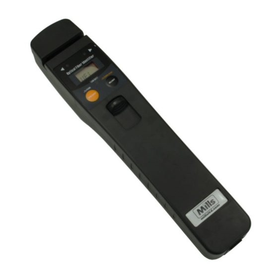
- Page 3 Description 1-Fiber location 2-Left indicative led 3-Power key of visual fault locator and optical power meter 4-Trigger of the fiber identifier 5-Right indicative led 6-Power indicative led 7-Calibration button 8-Connector of OPM/VFL ( optional )
- Page 4 Battery set Warning:At the same time, can not use different style and different capacitance batteries. 1.Push the tip 2.Open the battery slot 3.Replace the batteries 4.Close the battery slot...
- Page 5 Availabe for di erent Fiber 1.Available for 800nm~1700nm laser signal 2 Based on non-destructive technology 3 No need to replace the clamp block for dif ferent ber 250um bare ber 900um ber 2.5mm patch cord 3mm patch cord Availabe for di erent Fiber Silver indicative line When testing 2.5mm and 3.5mm patch cord, the silver indicative line needs to be seen to ensure a correct...
- Page 6 Fiber Identification models LOW BATT a.standard Optical Fiber Identfier >2s SAVE b.Optical Fiber Identifier c.Optical Fiber Identifier with OPM mode with VFL mode AFI430 serial has three models, include standard Optical Fiber Identifier, Optical Fiber Identifier with OPM mode and Optical Fiber Identifier with VFL mode.
- Page 7 Environment Light Calibration Calibration button Push down the trigger of the ber identi er and hold, then long press the button. Until the unit beeps and the the screen shows "CAL", the environment light calibration is nished.
-
Page 8: Operation
Operation Put the ber into the ber location and push down the trigger to begin testing. After 1~3 seconds, it will output the results. The data in the LCD shows the signal intensity, if the power value is over +5dBm, it will be "HI", if the value is less than -40dBm, it will be "LO". -
Page 9: Signal Direction
Signal Direction Right to left Left to right It is the main function to test the direction of the signal in the fiber. When signal is transporting in the fiber, the corresponding indicative led will be on. -
Page 10: Optical Power Meter
Optical Power Meter Power key Laser source wavelength switch key When the optical fiber identifier has OPM mode, press key to turn on the device, short press ON/OFF ON/OFF to select the laser source wavelength. Open the cap in the bottom of the device and connect the fiber correctly, the device will calculate the power value automatically. -
Page 11: Visual Fault Locator
Visual Fault Locator GLINT >2s SAVE >2s SAVE Power key Glint key When the optical fiber identifier has VFL mode,press key to turn on the device, press again to shut ON/OFF down. Open the cap in the bottom of the device, and press the key to open or close the flash laser. -
Page 12: Power Saving
Power saving Optical Fiber Identifier >2s SAVE >2s SAVE Power key Press to turn on the optical power meter or visual ON/OFF fault locator with auto power of f ( After 10 minutes if no key pressed, it will auto power of f. Press the key for 2 seconds when turning on the ON/OFF... - Page 13 Low power detecting Optical Fiber Identifier >2s SAVE >2s SAVE Low power indicative led When the power indicative led turns to red, it means low battery energy, please replace the batteries, otherwise the device will auto power off.
-
Page 14: Maintenance And Calibration
Maintenance and calibration Routine attention 1.Fiber-optical adapter should keep clean. 2.Please store the device in dry and ventilated place. 3. Please remove batteries if the device is not being used regularly to prevent battery leakage. Common malfunction Solution Described Malfunction cause No battery Check battery setting Can’t turn on... -
Page 15: Detailed Parameter
Detailed parameter 250um fiber@1550nm=-35dBm 250um fiber@1310nm=-30dBm Accuracy-CW 900um fiber@1550nm=-35dBm 900um fiber@1310nm=-30dBm 2.5mm fiber@1550nm=-30dBm 2.5mm fiber@1310nm=-25dBm Max. Input +5dBm Detector Type InGaAs Wave respond 800nm~1700nm <2.5dB typical value Insertion Loss Frequency Identify 270Hz/1KHz/2KHz Fiber Type 250um/900um/2.5mm/3mm fiber Sound Warn Optical Power Meter 850nm,1300nm,1310nm,1490nm,1550nm,1625nm Calibration Wave Accuracy...
Need help?
Do you have a question about the C00-6435 and is the answer not in the manual?
Questions and answers