Advertisement
Quick Links
S
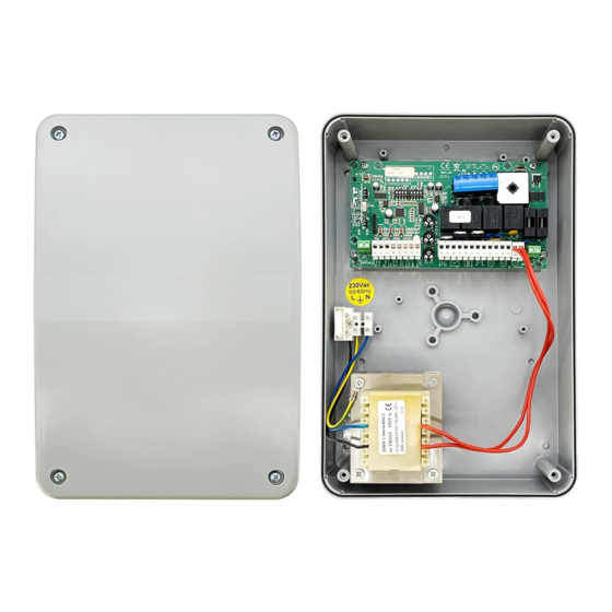
CR/41/24 29.41/24 CONTROL UNIT FOR CONTROL OF 1 OR 2 24 Vdc MOTORS FOR THE
Thank you for having chosen SERAI ELETTRONICA, certain that you will obtain the performance necessary for use
from this product.
Remember that you are about to install a system classified as "motorised activation destined to move gates and
automatic doors in commercial and residential buildings, with access of vehicles and persons", which is considered
as potentially dangerous. Normally, it is your task and responsibility to make this system "safe" for how mush this is
reasonably possible.
Installation and maintenance of such a system must therefore by carried out exclusively by train, qualified and exert
staff, with "state-of-the-art" executions, as prescribed by law 37/08 and successive amendments and integrations.
The law prohibits the realisation of these types of plants by unqualified staff.
On realisation of its own products, SERAI has respected the following:
Reference Directives for CE marking:
machinery:
low voltage:
electromagnetic compatibility:
General reference Standards:
electrical safety:
electromagnetic compatibility - emissions:
electromagnetic compatibility - immunity:
When installing the system, as well as that mentioned previously, please also respect.
General reference Standards:
safety of electrical plants in general environments:
Reference Standards specific of the product:
safety regarding use of motorised doors - requisites:
safety regarding use of motorised doors - test methods:
The SERAI products allow to realise systems that respond to these Standards. The following is very important
!
THE INSTALLER IS RESPONSIBLE FOR THE SYSTEM AND ITS FUNCTIONING IN COMPLIANCE WITH
STANDARDS
This manual must be read completely before proceeding with installation of the various parts of the plant.
E
INSTRUCTIONS FOR INSTALLATION
AUTOMATION FOR WING GATES
R
A
GATE OPENER DIVISION
2006/42/EEC
73/23/EEC + 93/68/EEC
2004/108/EEC
IEC EN60335-1 + IEC EN60335-2-103
IEC EN61000-6-3
IEC EN61000-6-1
IEC 64-8 V2
UNI EN12453
UNI EN12445
I
Page 1/12
Advertisement

Summary of Contents for Serai CR/41/24
- Page 1 CR/41/24 29.41/24 CONTROL UNIT FOR CONTROL OF 1 OR 2 24 Vdc MOTORS FOR THE AUTOMATION FOR WING GATES Thank you for having chosen SERAI ELETTRONICA, certain that you will obtain the performance necessary for use from this product. Remember that you are about to install a system classified as "motorised activation destined to move gates and automatic doors in commercial and residential buildings, with access of vehicles and persons", which is considered...
- Page 2 INSTALLATION OF THE CR/41/24 CONTROL UNIT WHERE TO POSITION THE CONTROL UNIT Position the appliance in proximity of the gate in a way to reduce the length of the connection cable, to the rest of the system, to a minimum.
- Page 3 BATTERY HOUSING AND CABLES INLET Two strips are supplied complete with screws for fixing the two 12V 2 Ah batteries (SERAI BT/15 or BT/20) onto the lid of the container Seats for fairleads PG11 and PG 13,5 which are easy to break through, are envisioned in the lower part of the...
- Page 4 WIRING DIAGRAM FOR 24Vdc MOTORS 2 Batteries 12Vdc 2Ah OPTIONAL 27 (+), 28 (-) BUFFER POWER SUPPLY for 2 12Vdc 2Ah batteries SERAI BT/15 or BT/20 -battery charger included- BATTERY 28 27 F1 F1 F2 F2 PAUSA LAVORO PROGR. 34 33...
-
Page 5: Leds Indication
- already wired - POWER SUPPLY Input for the connection of N°2 12V 2Ah buffer batteries (optionals, e.g. SERAI BT/15 or OPTIONAL BT/20) to guarantee functioning of the automation in the case of a power cut. In presence of... - Page 6 SETTING OF EACH INDIVIDUAL MICRO SWITCH ATTENTION: The micro switches must be regulated when the control unit is not powered. The regulations made to the micro switches become active on switch-on. We recommend, after having adjusted the micro switches, to program the work times (see control unit programming).
- Page 7 PROGRAMMING THE CONTROL UNIT The functioning time of the motors is controlled by two independent digital timers. If any control interrupts the run of the wing before the end, the timer stops and the time passed is memorised. The appliance is therefore able to establish the partial work time necessary to terminate the wing run, with a certain approximation, always slowing in the programmed point.
- Page 8 MANUAL PROGRAMMING FOR GATE WITH TWO WINGS (DIP1 SW1 OFF) The installer sets work times, slowing point and phase difference time according to requirements Regulate the "AMP", "RALL", "VELOC." potentiometers according to requirements. With the control unit powered and gate closed, press and release button P3 (PROGR), the DL6 LED starts to flash to indicate that the control unit is found in the programming state.
- Page 9 PROGRAMMING OPEN GATE PAUSE TIME (AUTOMATIC RE-CLOSURE) ACTIVATE AUTOMATIC RE-CLOSURE (maximum time that can be set 120s) With the control unit powered and gate closed, press key P3 (PROGR.) once. The LD6 LED starts to flash indicating that the board has entered the programming phase. Press key P1 once (PAUSE), the control unit starts the open gate pause count, highlighted with fast flashing of the DL6 LED and of the flashing light.
- Page 10 LEARNING THE RADIO CONTROL CODE The circuit board incorporates a dual-channel radio receiver at 433.92 MHz, which allows to control the gate at a distance via micro switch remote controls from the OG/02, OG/04 range and self-learning remote controls from the OG/62, OG/64, OG/28, OG/48, OG/52, OG/54, OG/82/1 and OG/84 range.
- Page 11 When the mains voltage returns, the built-in battery charger charges and maintains the batteries in this state. Twenty-four hours are required for complete re-charging. TECHNICAL DATA OF THE CR/41/24 CONTROL UNIT Power supply transformer: 230/20 Vac, 130VA Internal battery charger capacity 28Vdc, 0.5A...
-
Page 12: Troubleshooting
TERMS OF GUARANTEE The company reserves the right to make modifications to the equipment without prior notice thereof. SERAI products are covered by a standard guarantee with a term of 24 months. Coverage starts on the date on which the tax document constituting proof of purchase is issued and guarantee services shall be provided on the company's premises at Legnaro - PD - or at the Authorised Service Centres.
Need help?
Do you have a question about the CR/41/24 and is the answer not in the manual?
Questions and answers