Table of Contents

Related Manuals for Itelco-Clima VLS Series

Summary of Contents for Itelco-Clima VLS Series
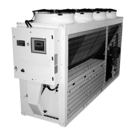
- Page 1 Installation and Maintenance Instructions VLS/VLC/VLH English 126,8 kW Air-Cooled Water Chillers and Heat Pumps 313 kW 125,6kW 293,5 kW IOM 05 VLS VLH I N Code 35B09048-000-A Supersedes and Replaces: 35B09048-000 “Notified Body No. 1115 ”...
-
Page 2: Table Of Contents
Table of contents Table of contents 1 FOREWORD 5 START-UP 1.1 Introduction 5.1 Preliminary check 1.2 Warranty 5.2 Start-up 1.3 Emergency stop/Normal stop 5.3 Checking the operation 1.4 An introduction to this manual 5.4 Delivery to the customer 2 SAFETY 6 CONTROL 2.1 Foreword 6.1 Main Characteristics... - Page 3 Table of contents 9 MAINTENANCE 9.1 General requirements 9.2 Planned maintenance 9.3 Refrigerant charge 9.4 Compressor 9.5 Condenser 9.6 Fans 9.7 Dehydrating filter 9.8 Sight glass 9.9 Thermostatic expansion valve 9.10 Evaporator 10 TROUBLESHOOTING 11 SPARE PARTS 11.1 Spare parts list 11.2 Oil for compressors 11.3 Wiring diagram 12 DISMANTLING, DEMOLITION...
-
Page 4: Foreword
This warranty shall apply providing that the installa- tion instructions have been complied with (either is- sued by Itelco-Clima, or deriving from the current practice), and the Form 1 (“Start-up”) has been filled- in and mailed to Itelco-Clima (attn. After-Sales Ser- vice). -
Page 5: Safety
– The maximum working pressure values are men- Itelco-Clima unit has been installed; he/she has the tioned on the unit’s data plate. responsibility of making sure that all the safety regu- lations specified in this manual are complied with, –... -
Page 6: Access To The Unit
OPERATOR: means a person authorised by the own- use tools in a good state of repair; be sure to have er to do on Itelco-Clima unit all the regulation and understood the instructions before using them control operations expressly described in this manu-... -
Page 7: Precautions During Maintenance Operations
Itelco-Clima or the official retailers of the com- do not bend/hit pipes containing fluids under pres- panies on the recommended spare parts list... -
Page 8: Safety Labels
Safety 2.7 Safety labels The labels below will be affixed to each unit in the in- dicated point: Identification of the refrigerant - External door Gravity centre - Base Identification of the unit - Electrical warning Outside, on the right-hand front column Adjacent to the master switch Page 7... - Page 9 Safety ATTENZIONE INSERIRE LE RESISTENZE DI RISCALDAMENTO OLIO ALMENO 12 ORE PRIMA DI OGNI AVVIAMENTO (SE PREVISTE). PRIMA DELLA MESSA IN TENSIONE ASSICURARSI CHE LE VITI DEI CIRCUITI ELETTRICI SIANO SERRATE COMPLETAMENTE . WARNING ENERGIZE THE CRANCKCASE HEATER FOR AT LEAST 12 HOURS BEFORE EACH STARTING (IF FITTED).
-
Page 10: Safety Regulations
Safety Safety regulations Safety data: R407C, R134a Refrigerant data Toxicity Contact with skin If sprayed, the refrigerant is likely to cause frost burns. If absorbed by the skin, the danger is very limited; it may cause a slight irritation, and the liquid is degreasing. - Page 11 Safety General precautions Do not inhale concentrated vapours. Their concentration in the atmos- phere should not exceed the minimum preset values and should be maintained below the professional threshold. Being more weighty than the air, the vapour concentrates on the bottom, in narrow areas. There- fore, the exhaust system must work at low level.
- Page 12 Safety Safety data: Polyolester oil (POE) Refrigerant oil data Classification Not harmful May cause slight irritation. Does not require first aid measures. It is rec- Contact with skin ommended to follow usual personal hygiene measures, including wash- ing the exposed skin with soap and water several times a day. It is also recommended to wash your overalls at least once a week.
-
Page 13: Transport, Lifting And Positioning
In the presence of any serious damage, that does not affect the surface only, it is recommended to inform Itelco-Clima immediately. Please note that Itelco-Clima may not be held liable for any damage to the equipment during transporta- tion, even though the carrier has been appointed by the factory. -
Page 14: Anchoring
Transport, Lifting and Positioning For lifting operations, use only tools and material fit for this purpose, in accordance with accident-prevention regulations. During the lifting and handling of the unit, be careful not to damage the finned pack of the coils positioned on the sides of the unit. The sides of the unit must be protected by cardboard or plywood sheets. -
Page 15: Installation
Installation INSTALLATION the unit must not be installed in air shafts, narrow courts or other small places, where the noise may be reflected by the walls or the air ejected by fans 4.1 Positioning of the unit may short-circuit itself on refrigerant/air heat ex- changers or condenser Before installing the unit, make sure that the structure of the building and/or the support-... -
Page 16: External Hydraulic Circuit
Installation The external hydraulic circuit should consist of the fol- lowing elements: A circulation pump that can ensure the necessary capacity and discharge head. The capacity of the primary hydraulic circuit should not be less than 7.5 litres/KW of cooling capacity, in order to prevent the repeated start-up of the compressor and any damage to it. -
Page 17: Hydraulic Connection
Installation Then: Provide the evaporator with a by-pass circuit equipped with a valve to wash the plant. Insulate the piping, to prevent the risk of heat loss. Position a filter on the suction side of the evapora- tor of the heat recovery condenser. Legends: GA: Flexible hoses Pressure gauge connection... -
Page 18: Power Supply
(User’s Terminal Box) provided in this manual and according to the wiring diagram which accompanies the unit. Itelco-Clima may not be held liable for any damage Before connecting the power supply lines, and/or injury caused by failure to comply with these check that the available voltage value does precautions. - Page 19 Installation VLS/VLH Version – Electrical Connections TERMINAL BOARD ON THE MACHINE USER'S CONNECTIONS POWER LINE 400/3/50-PE DISCONNECTING SWITCH ON-OFF REMOTE CONTROL REMOTE COLD/HEAT SECTION (CLOSED = HEATING) (HEAT PUMP ONLY) FLOW METER OR EXTERNAL INTERLOCK INTERLOCK (OPTIONAL) CIRCULATING PUMP ETC. N.O.
- Page 20 Installation VLC version – Electrical Connections Page 19...
-
Page 21: Start-Up
Check that the oil in the compressor has reached the requested temperature (the minimum tempera- The operations carried out by Itelco-Clima ture outside the pan must be approx. 40°C) and personnel are limited to the start-up of the that the auxiliary control circuit is energised. -
Page 22: Checking The Operation
Start-up 5.3 Checking the operation Check the following: The temperature of the water entering the evapo- rator. The temperature of the water leaving the evapora- tor. The level of the water flow rate in the evaporator, if possible. The current absorption upon the start of the com- pressor and in case of stabilised operation. -
Page 23: Control
Control CONTROL menu prog 6.1 Main characteristics on-off alarm enter info - Microprocessor control. - Accessible, easy to use control keyboard for the user. Access the display mask of the inlet/out- - Proportional or proportional + integr. control on let water temperature and machine sta- return water temperature (RWT). - Page 24 Control Display on-off alarm enter The display is of the backlighted LCD type, 4 lines x 20 columns. Figure 1 The quantities and the information about operation are alternated in the form of subsequent screens 1.on/off key: allows you to turn the unit on/off. The known as masks.
- Page 25 Control Alarm table Code Alarm description Comp Pump Aut/Man Delay Notes Status Status Status Reset AL01 CPS efficiency alarm 30 sec AL02 Sys 1 Antifreeze alarm Off Sys 1 AL03 Sys 2 Antifreeze alarm Off Sys 2 AL04 Flow meter alarm Parameter AL05 Sys 1 Low pressure...
-
Page 26: Protection And Safety Equipment
Control 6.2 Protection and Safety Equipment Compressor Protection Defrosting System Compressors are equipped with a heating element (only for VLH models) to prevent oil dilution, which may result in remark- able risks of failure of compressors. The VLH units are provided with an automatic de- frosting system, which prevents the formation of ex- The windings of the compressors’... -
Page 27: General Description
General Description GENERAL DESCRIPTION 7.1 Introduction cations in industrial processes. The VLS/VLH units are water chillers /air-water heat These units can be installed outdoor on the roof of a pumps provided with hermetic scroll compressors building or at ground level. with two refrigeration circuits. -
Page 28: Air Heat Exchanger
General Description The hydraulic connections to the evaporator are of 2” 7.7 Fans Victaulic type on 504 – 804 units and 3” Victaulic type on 904 – 1204 units. Fans are of directly coupling propeller type, provid- ed with aluminium blade with wing profile. 7.6 Air heat exchanger Each fan is provided with galvanised steel accident- prevention guard. -
Page 29: Electric Power Supply And Control System
General Description VLC refrigeration diagram Components: Safety and control devices: Compressor HP pressure switch Air heat exchanger LP pressure switch Ball cock HP transducer LP transducer Differential pressure switch Air temperature sensor 7.8 Electric power supply and Fan speed regulator control system The speed regulator of the fans is mounted as a stan- dard accessory for the Extra Low Noise units, and is... - Page 30 General Description RS 485 MODBUS serial card A communication interface makes it possible to con- trol and manage the unit from a local station, with RS485 connection, up to a distance of 1,000m. It is possible to obtain the remote control and the management, by inserting the control into the man- agement plant of the building.
-
Page 31: Technical Data
Technical data TECHNICAL DATA 8.1 Pressure drops PRESSURE DROPS IN THE EVAPORATOR VLS 504 VLS 554 VLS 604 VLS 704 VLS 804 VLS 904 VLS 1004 VLS 1104 VLS 1204 Min. water flow rate Nominal flow rate 11,2 12,6 13,9 15,0 Max. -
Page 32: Technical Data
Technical data 8.2 Technical data VLS STD 1004 1104 1204 Power supply V/ph/Hz 400 (± 10%)/3/50 Number of circuits Number of steps Capacity steps Refrigerant Type R407C Charge (1) 18,5 20,3 25,2 23,3 27,3 29,1 32,0 34,3* 36,8* Compressors Type Scroll Scroll Scroll... - Page 33 Technical data VLS LN 1004 1104 1204 Power supply V/ph/Hz 400 (± 10%)/3/50 Number of circuits Number of steps Capacity steps Refrigerant Type R407C Charge (1) 21,3* 22,0 25,4 23,0 27,3* 29,0 32,0 34,3* 36,8* Compressors Type Scroll Scroll Scroll Scroll Scroll Scroll...
- Page 34 Technical data VLS ELN 1004 1104 1204 Power supply V/ph/Hz 400 (± 10%)/3/50 Number of circuits Number of steps Capacity steps Refrigerant Type R407C Charge (1) 19,3 25,0 25,2 24,0 30,8 31,5 36,0 34,3* 36,8* Compressors Type Scroll Scroll Scroll Scroll Scroll Scroll...
- Page 35 Technical data VLS HE 1004 Power supply V/ph/Hz 400 (± 10%)/3/50 Number of circuits Number of steps Capacity steps Refrigerant Type R407C Charge (1) 21,4* 22,0 23,9* 25,8* 30,0 29,0 32,5* Compressors Type Scroll Scroll Scroll Scroll Scroll Scroll Scroll Number Start-up type Direct...
- Page 36 Technical data VLC STD 1004 1104 1204 Power supply V/ph/Hz 400 (± 10%)/3/50 Number of circuits Number of steps Capacity steps Refrigerant Type R407C Compressors Type Scroll Scroll Scroll Scroll Scroll Scroll Scroll Scroll Scroll Number Start-up type Direct Direct Direct Direct Direct...
- Page 37 Technical data VLC LN 1004 1104 1204 Power supply V/ph/Hz 400 (± 10%)/3/50 Number of circuits Number of steps Capacity steps Refrigerant Type R407C Compressors Type Scroll Scroll Scroll Scroll Scroll Scroll Scroll Scroll Scroll Number Start-up type Direct Direct Direct Direct Direct...
- Page 38 Technical data VLC ELN 1004 1104 1204 Power supply V/ph/Hz 400 (± 10%)/3/50 Number of circuits Number of steps Capacity steps Refrigerant Type R407C Compressors Type Scroll Scroll Scroll Scroll Scroll Scroll Scroll Scroll Scroll Number Start-up type Direct Direct Direct Direct Direct...
- Page 39 Technical data VLC HE 1004 Power supply V/ph/Hz 400 (± 10%)/3/50 Number of circuits Number of steps Capacity steps Refrigerant Type R407C Compressors Type Scroll Scroll Scroll Scroll Scroll Scroll Scroll Number Start-up type Direct Direct Direct Direct Direct Direct Direct Fans Number...
- Page 40 Technical data VLH STD 1004 1104 1204 Power supply V/ph/Hz 400 (±10%)/3/50 Number of circuits Number of steps Capacity steps Refrigerant Type R407C Charge (1) Compressors Type Scroll Scroll Scroll Scroll Scroll Scroll Scroll Scroll Scroll Number Start-up type Direct Direct Direct Direct...
- Page 41 Technical data VLH LN 1004 1104 1204 Power supply V/ph/Hz 400 (+ - 10 %)/3/50 Number of circuits Number of steps Capacity steps Refrigerant Type R407C Charge (1) 40,5 Compressors Type Scroll Scroll Scroll Scroll Scroll Scroll Scroll Scroll Scroll Number Start-up type Direct...
- Page 42 Technical data VLH ELN 1004 1104 1204 Power supply V/ph/Hz 400 (+ - 10 %)/3/50 Number of circuits Number of steps Capacity steps Refrigerant Type R407C Charge (1) 29,3 37,5 Compressors Type Scroll Scroll Scroll Scroll Scroll Scroll Scroll Number Start-up type Direct Direct...
- Page 43 Technical data VLH HE 1004 Power supply V/ph/Hz 400 (+ - 10%)/3/50 Number of circuits Number of steps Capacity steps Refrigerant Type R407C Charge (1) Compressors Type Scroll Scroll Scroll Scroll Scroll Scroll Scroll Number Start-up type Direct Direct Direct Direct Direct Direct...
-
Page 44: Electrical Data
Technical data 8.3 Unit Electrical Data VLS/VLC STD 1004 1104 1204 Rated voltage V-ph-Hz 400 (±10%)/3/50 Max. absorbed power 59,4 67,4 72,0 Rated current 85,6 102,6 119,5 133,7 150,6 164,8 N.D. Max. current FLA 101,8 111,8 122,2 Max. start-up current LRA External fuses Max. - Page 45 Technical data Unit Electrical Data VLS/VLC HE 1004 Rated voltage V-ph-Hz 400 (±10%)/3/50 Max. absorbed power 60,8 68,8 73,4 Rated current 81,3 96,7 105,3 Max. current FLA 104,5 114,5 124,9 Max. start-up current LRA External fuses Max. cable section (*) 3x95 3x95 3x120...
- Page 46 Technical data Fans Electrical Data VLS/VLC STD 1004 1104 1204 Power supply V(%)-ph-Hz 400 (±10%)/3/50 Number Rated power Absorbed rated current FLA VLS/VLC LN 1004 1104 1204 Power supply V(%)-ph-Hz 400 (±10%)/3/50 Number Rated power 0,94 0,94 0,94 0,95 0,95 0,95 0,95 Absorbed rated current FLA...
- Page 47 Technical data Unit Electrical Data VLH STD 1004 1104 1204 Rated voltage V-ph-Hz 400 (±10%)/3/50 Max. absorbed power 59,4 67,4 88,2 104,6 110,3 112,3 Rated current 85,6 102,6 123,4 137,6 155,8 N.D. N.D. Max. current FLA 101,8 111,8 122,2 147,4 164,8 186,8 204,8...
- Page 48 Technical data Unit Electrical Data VLH HE 1004 Rated voltage V-ph-Hz 400 (±10%)/3/50 Max. absorbed power 60,8 68,8 73,4 90,2 100,6 112,3 Rated current 88,3 96,7 105,3 127,4 141,6 155,8 Max. current FLA 104,5 114,5 124,9 151,4 168,8 186,8 204,8 Max.
- Page 49 Technical data Fans Electrical Data VLH STD 1004 1104 1204 Power supply V(%)-ph-Hz 400 (±10%)/3/50 Number Rated power Max. current FLA Max. start-up current LRA 14,0 14,0 14,0 14,0 14,0 14,0 VLH LN 1004 1104 1204 Power supply V(%)-ph-Hz 400 (±10%)/3/50 Number Rated power 0,94...
-
Page 50: Position Of Shock Absorbers And Weight Distribution On Supports
Technical data 8.4 Position of shock absorbers and weight distribution on supports VLS 504-604 P1 - P4 Unit positions VLS 504 - 604 Al/Cu Standard Version Distribution Weights (kg) Operating Shipping CENTRE OF GRAVITY P1-P4 Weight Weight POSITIONS POSITIONS Al/Cu ( kg ) ( kg ) ( kg ) - Page 51 Technical data VLS 504 - 604 Cu/Cu Standard Version Distribution Weights (kg) Operating Shipping CENTRE OF GRAVITY P1-P4 Weight Weight POSITIONS POSITIONS Cu/Cu ( kg ) ( kg ) ( kg ) ( kg ) ( kg ) ( kg ) a (mm)* b (mm) c (mm)
- Page 52 Technical data VLS 704-1204 P1 - P6 Unit positions VLS 704 - 1204 Al/Cu Standard Version CENTRE Distribution Weights (kg) Operating Shipping P1-P6 OF GRAVITY Weights Weights POSITIONS Al/Cu POSITIONS ( kg ) ( kg ) ( kg ) ( kg ) ( kg ) ( kg ) ( kg )
- Page 53 Technical data VLS 704 - 1004 Al/Cu High Efficiency Version CENTRE Distribution Weights (kg) Operating Shipping P1-P6 OF GRAVITY Weights Weights POSITIONS Al/Cu POSITIONS ( kg ) ( kg ) ( kg ) ( kg ) ( kg ) ( kg ) ( kg ) ( kg ) a (mm)*...
- Page 54 Technical data VLC 504-604 P1 - P4 Unit positions VLC 504 - 604 Al/Cu Standard Version Distribution Weights (kg) Shipping CENTRE OF GRAVITY P1-P4 Weight POSITIONS POSITIONS Al/Cu ( kg ) ( kg ) ( kg ) ( kg ) ( kg ) a (mm)* b (mm)
- Page 55 Technical data VLC 504 - 604 Cu/Cu Standard Version Distribution Weights (kg) Shipping CENTRE OF GRAVITY P1-P4 Weight POSITIONS POSITIONS Cu/Cu ( kg ) ( kg ) ( kg ) ( kg ) ( kg ) a (mm)* b (mm) c (mm) x (mm) y (mm)
- Page 56 Technical data VLC 704-1204 P1 - P6 Unit positions VLC 704 - 1204 Al/Cu Standard Version CENTRE Distribution Weights (kg) Shipping P1-P6 OF GRAVITY Weights POSITIONS Al/Cu POSITIONS ( kg ) ( kg ) ( kg ) ( kg ) ( kg ) ( kg ) ( kg )
- Page 57 Technical data VLC 704-1004 Al/Cu High Efficiency Version CENTRE Distribution Weights (kg) Shipping P1-P6 OF GRAVITY Weights POSITIONS Al/Cu POSITIONS ( kg ) ( kg ) ( kg ) ( kg ) ( kg ) ( kg ) ( kg ) a (mm)* b (mm) c (mm)
- Page 58 Technical data VLH 504-604 P1 - P4 Unit positions VLH 504 - 604 Al/Cu Standard Version Distribution Weights (kg) Operating Shipping CENTRE OF GRAVITY P1-P4 Weight Weight POSITIONS POSITIONS Al/Cu ( kg ) ( kg ) ( kg ) ( kg ) ( kg ) ( kg ) a (mm)*...
- Page 59 Technical data VLH 504 - 604 Cu/Cu Standard Version Distribution Weights (kg) Operating Shipping CENTRE OF GRAVITY P1-P4 Weight Weight POSITIONS POSITIONS Cu/Cu ( kg ) ( kg ) ( kg ) ( kg ) ( kg ) ( kg ) a (mm)* b (mm) c (mm)
- Page 60 Technical data VLH 704-1204 P1 - P6 Unit positions VLH 704 - 1204 Al/Cu Standard Version CENTRE Distribution Weights (kg) Operating Shipping P1-P6 OF GRAVITY Weights Weights POSITIONS Al/Cu POSITIONS ( kg ) ( kg ) ( kg ) ( kg ) ( kg ) ( kg ) ( kg )
- Page 61 Technical data VLH 704 - 1004 Al/Cu High Efficiency Version CENTRE Distribution Weights (kg) Operating Shipping P1-P6 OF GRAVITY Weights Weights POSITIONS Al/Cu POSITIONS ( kg ) ( kg ) ( kg ) ( kg ) ( kg ) ( kg ) ( kg ) ( kg ) a (mm)*...
-
Page 62: Overall Dimensions
Technical data 8.5 Overall dimensions Units VLS 504-604 STD & VLS 504-554 LN VLH 504-604 STD & VLH 504-554 LN WATER CONNECTION WATER OUTLET “A” 2” 1/2 M WATER INLET “B” (with pump) 2” 1/2 M WATER INLET “C” (without pump) 2”... - Page 63 Technical data Dimensions - Units VLS 504-604 HE/ELN & VLS 604 LN VLH 504-554 HE & VLH 604 LN/HE WATER CONNECTIONS WATER OUTLET “A” 2” 1/2 M WATER INLET “B” (with pump) 2” 1/2 M WATER INLET “C” (without pump) 2”...
- Page 64 Technical data Dimensions - Unit VLH 604 ELN WATER CONNECTIONS WATER OUTLET “A” 2” 1/2 M WATER INLET “B” (with pump) 2” 1/2 M WATER INLET “C” (without pump) 2” 1/2 M DESUPERHEATER IN/OUT “D” 4x1”F Page 63...
- Page 65 Technical data Dimensions - Units VLS 704-804 STD/LN VLH 704-804 STD/LN WATER CONNECTIONS WATER OUTLET “A” 2” 1/2 M WATER INLET “B” (with pump) 2” 1/2 M WATER INLET “C” (without pump) 2” 1/2 M DESUPERHEATER IN/OUT “D” 4x2” F (*) Measure with desuperheater.
- Page 66 Technical data Dimensions Units VLS 704-804 HE/ELN & VLS 904-1004 STD/LN/HE/ELN & VLS 1104-1204 STD/LN/ELN VLH 704-804 HE/ELN & VLH 904-1004 STD/LN/HE/ELN & VLH 1104-1204 STD/LN/ELN Dimensions (mm) 704-804 904-1204 WATER CONNECTIONS 704-804 904-1204 WATER OUTLET “A” 2” 1/2 M 3”...
- Page 67 Technical data Dimensions - Units VLC 504-554 STD/LN & VLC 604 STD Dimensions - Units VLC 504-554 ELN/HE & VLC 604 LN/ELN/HE Page 66...
- Page 68 Technical data Dimensions - Units VLC 704-804 STD/LN Dimensions Units VLC 704-804 ELN/HE & VLC 904-1004 STD/LN/ELN/HE & VLC 1104-1204 STD/LN/ELN Page 67...
- Page 69 Technical data Dimensions - Units with pumps VLS 504-604 STD/LN/ELN/HE VLH 504-604 STD/LN/HE Dimensions - Units with pumps VLS 704-1204 STD/LN/ELN & VLS 704-1004 HE VLH 604-1204 ELN & VLH 704-1204 STD/LN & VLH 704-1004 HE Page 68...
-
Page 70: Services Spaces
Technical data 8.6 Service spaces VLS/VLC/VLH All models Installation of Single Units Installation of several Units ARRANGEMENT 1 ARRANGEMENT 1 A and C SCREENED A and B SOLID A and C SOLID A and B SCREENED A and D SCREENED B and D SOLID C and D SOLID B and D SCREENED... -
Page 71: Maintenance
Check the operation tions. If you are in doubt, please contact Itelco-Clima • • of the solenoid valve Service Centre. -
Page 72: Refrigerant Charge
In the presence of leaks caused by any damage or shock, the coils shall be repaired or replaced by one of Itelco-Clima’s authorised Service Centers. To ensure the effective and correct opera- tion of the condenser coils, it is important to keep the Fill the refrigeration circuit after it has been drained condenser’s surface perfectly clean, and to check... -
Page 73: Dehydrating Filter
Maintenance 9.7 Dehydrating filter Make the adjusting screw follow a complete turn, and operate the appliance for five minutes. Check again and, if necessary, repeat the regula- The refrigeration circuits are provided with dehydrat- tion. ing filters. The filter clogging is marked by the presence of air If the expansion valve cannot be regulated, it is prob- bubbles in the sight glass, or by the difference be- ably broken, and shall be replaced. -
Page 74: Troubleshooting
10 TROUBLESHOOTING The table below lists the anomalies of operation of the unit, the relevant causes and the corrective measures. For anomalies of any other type or not listed, contact one of Itelco-Clima’s Service Centre for technical assis- tance. Anomaly... - Page 75 Troubleshooting Anomaly Cause Operation One or both compressors Breaking of the electric circuit. Check the electric circuit and detect are not working. any ground dispersions and short cir- cuits. Check fuses. Intervention of the HP pressure Reset the pressure switch and the con- switch.
-
Page 76: Spare Parts
The compressors are lubricated with polyester oil (P.O.E.). 11.3 Wiring diagrams The wiring diagrams are installed inside the doors of the electrical panels of the unit. Any request for wiring diagrams shall be forwarded to Itelco-Clima’s Service Centre.. Page 75... -
Page 77: Dismantling, Demolition And Scrapping
Dismantling, Demolition and Scrapping 12 DISMANTLING, DEMOLITION After draining operations, the piping of the hydraulic networks can be disconnected and disassembled. AND SCRAPPING Once they have been disconnected as specified, the During the draining of the refrigeration cir- packaged units can be disassembled in a single cuits, do not let the refrigerant overflow in piece. - Page 78 With a concern for a constant improvement, our products can be modified without notice. Photos non contractual. ITELCO-CLIMA S.r.l. - Via XXV Aprile, 29 - 20030 Barlassina (MI) - Tel. +39 0362 6801 - Fax +39 0362 680281 www.itelco-clima.com - info@itelco-clima.com...
Need help?
Do you have a question about the VLS Series and is the answer not in the manual?
Questions and answers