Table of Contents
Advertisement
Available languages
Available languages
Quick Links
Advertisement
Table of Contents

Related Manuals for MKS 141A Series


Summary of Contents for MKS 141A Series
- Page 1 112905-P1 Rev C, 8/98 MKS Type 141A/142A Vacuum Pressure Switch...
- Page 2 All rights reserved. No part of this work may be reproduced or transmitted in any form or by any means, electronic or mechanical, including photocopying and recording, or by any information storage or retrieval system, except as may be expressly permitted in writing by MKS Instruments, Inc.
-
Page 3: Table Of Contents
Table of Contents Table of Contents Pressure Transducer Safety Information................1 Symbols Used in This Instruction Manual..............1 Symbols Found on the Unit ..................2 Safety Procedures and Precautions................3 Informations relatives à la sécurité pour le transducteur de pression ........5 Symboles utilisés dans ce manuel d'utilisation ............5 Symboles apparaissant sur l'unité................6 Mesures de sécurité... - Page 4 Table of Contents Electrical Information .....................24 Chapter Three: Overview ....................25 General Information....................25 Labels ........................27 Serial Number Label...................27 Chapter Four: Operation.....................29 General Information....................29 How To Adjust the Relay Set Point................29 How To Activate Fail-Safe Operation ..............30 Chapter Five: Maintenance....................31 General Information....................31 How To Clean the Unit ................31 Maintenance......................31 Appendix A: Product Specifications..................33...
- Page 5 List of Figures and Tables List of Figures and Tables Figures Figure 1: Dimensions of a Type 141 Vacuum Pressure Switch..........21 Figure 2: Dimensions of a Type 142 Vacuum Pressure Switch..........22 Figure 3: Terminal Block Connections................24 Figure 4: Type 141/142 Block Diagram................26 Figure 5: Serial Number Label....................27 Tables Table 1: Definition of Symbols Found on the Unit ...............2...
- Page 6 List of Figures and Tables...
-
Page 7: Pressure Transducer Safety Information
Pressure Transducer Safety Information Symbols Used in This Instruction Manual Pressure Transducer Safety Information Symbols Used in This Instruction Manual Definitions of WARNING, CAUTION, and NOTE messages used throughout the manual. Warning The WARNING sign denotes a hazard to personnel. It calls attention to a procedure, practice, condition, or the like, which, if not correctly performed or adhered to, could result in injury to personnel. -
Page 8: Symbols Found On The Unit
Symbols Found on the Unit Pressure Transducer Safety Information Symbols Found on the Unit The following table describes symbols that may be found on the unit. Definition of Symbols Found on the Unit Protective earth (ground) Earth (ground) On (Supply) Off (Supply) IEC 417, No.5017 IEC 417, No.5019... -
Page 9: Safety Procedures And Precautions
DO NOT SUBSTITUTE PARTS OR MODIFY INSTRUMENT Do not install substitute parts or perform any unauthorized modification to the instrument. Return the instrument to an MKS Calibration and Service Center for service and repair to ensure that all safety features are maintained. - Page 10 Safety Procedures and Precautions Pressure Transducer Safety Information OPERATE AT SAFE INLET PRESSURES Never operate at pressures higher than the rated maximum pressure (refer to the product specifications for the maximum allowable pressure). INSTALL A SUITABLE BURST DISC When operating from a pressurized gas source, install a suitable burst disc in the vacuum system to prevent system explosion should the system pressure rise.
-
Page 11: Informations Relatives À La Sécurité Pour Le Transducteur De Pression
Informations relatives à la sécurité pour le Symboles utilisés dans ce manuel d'utilisation transducteur de pression Informations relatives à la sécurité pour le transducteur de pression Symboles utilisés dans ce manuel d'utilisation Définitions des indications AVERTISSEMENT, ATTENTION, et REMARQUE utilisées dans ce manuel. -
Page 12: Symboles Apparaissant Sur L'unité
Symboles apparaissant sur l'unité Informations relatives à la sécurité pour le transducteur de pression Symboles apparaissant sur l'unité Le tableau suivant décrit les symboles pouvant apparaître sur l'unité. Définition des symboles apparaissant sur l'unité Marche Terre de protection (sous tension) Arrêt (hors tension) Terre (masse) (masse) -
Page 13: Mesures De Sécurité Et Précautions
Ne pas installer des pièces de substitution ou effectuer des modifications non autorisées sur l'appareil. Renvoyer l'appareil à un centre de service et de calibrage MKS pour tout dépannage ou réparation afin de garantir le l'intégrité des dispositifs de sécurité. - Page 14 Mesures de sécurité et précautions Informations relatives à la sécurité pour le transducteur de pression VÉRIFICATION DE L'ÉTANCHÉITÉ DES CONNEXIONS Vérifier attentivement toutes les connexions des composants pour le vide afin de garantir l'étanchéité de l'installation. EXPLOITATION AVEC DES PRESSIONS D'ENTRÉE NON DANGEREUSES Ne jamais utiliser des pressions supérieures à...
-
Page 15: Sicherheitshinweise Für Den Druckmeßwertwandler
Sicherheitshinweise für den Druckmeßwertwandler In dieser Betriebsanleitung vorkommende Symbole Sicherheitshinweise für den Druckmeßwertwandler In dieser Betriebsanleitung vorkommende Symbole Bedeutung der mit WARNUNG!, VORSICHT! und HINWEIS gekennzeichneten Absätze in dieser Betriebsanleitung. Warnung! Das Symbol WARNUNG! weist auf eine Gefahr für das Bedienpersonal hin. -
Page 16: Erklärung Der Am Gerät Angebrachten Symbole
Erklärung der am Gerät angebrachten Symbole Sicherheitshinweise für den Druckmeßwertwandler Erklärung der am Gerät angebrachten Symbole Nachstehender Tabelle sind die Bedeutungen der Symbole zu entnehmen, die am Gerät angebracht sein können. Bedeutung der am Gerät angebrachten Symbole Ein (Netz) Aus (Netz) Erde Schutzerdung IEC 417, No.5007... -
Page 17: Sicherheitsvorschriften Und Vorsichtsmaßnahmen
Ersetzen Sie keine Teile mit baugleichen oder ähnlichen Teilen, und nehmen Sie keine eigenmächtigen Änderungen am Gerät vor. Schicken Sie das Instrument zwecks Wartung und Reparatur an den MKS-Kalibrierungs- und -Kundendienst ein. Nur so wird sichergestellt, daß alle Schutzvorrichtungen voll funktionsfähig bleiben. - Page 18 Sicherheitsvorschriften und Vorsichtsmaßnahmen Sicherheitshinweise für den Druckmeßwertwandler Anweisungen zum Installieren der Armaturen Alle Anschlußstücke und Armaturenteile müssen mit der Gerätespezifikation übereinstimmen, und mit dem geplanten Einsatz des Instrumentes kompatibel sein. Der Einbau, insbesondere das Anziehen und Abdichten, muß gemäß den Anweisungen des Herstellers vorgenommen werden. Verbindungen auf Undichtigkeiten prüfen! Überprüfen Sie sorgfältig alle Verbindungen der Vakuumkomponenten auf undichte Stellen.
-
Page 19: Medidas De Seguridad Del Transductor De Presión
Medidas de seguridad del transductor de presión Símbolos usados en este manual de instrucciones Medidas de seguridad del transductor de presión Símbolos usados en este manual de instrucciones Definiciones de los mensajes de advertencia, precaución y de las notas usados en el manual. Advertencia El símbolo de advertencia indica la posibilidad de que se produzcan daños personales. -
Page 20: Símbolos Hallados En La Unidad
Símbolos hallados en la unidad Medidas de seguridad del transductor de presión Símbolos hallados en la unidad La tabla siguiente contiene los símbolos que puede hallar en la unidad. Definición de los símbolos hallados en la unidad Encendido Apagado (alimentación eléctrica) (alimentación eléctrica) Puesta a tierra Protección a tierra... -
Page 21: Procedimientos Y Precauciones De Seguridad
No instale piezas que no sean originales ni modifique el instrumento sin autorización. Para asegurar el correcto funcionamiento de todos los dispositivos de seguridad, envíe el instrumento al Centro de servicio y calibración de MKS toda vez que sea necesario repararlo o efectuar tareas de mantenimiento. - Page 22 Procedimientos y precauciones de seguridad Medidas de seguridad del transductor de presión USE ACCESORIOS ADECUADOS Y REALICE CORRECTAMENTE LOS PROCEDIMIENTOS DE AJUSTE Todos los accesorios del instrumento deben cumplir las especificaciones del mismo y ser compatibles con el uso que se debe dar al instrumento. Arme y ajuste los accesorios de acuerdo con las instrucciones del fabricante.
-
Page 23: Chapter One: General Information
100° C to help minimize effluent contamination build-up. The 141/142 switches combine the proven MKS Type 127 high accuracy sensor with full scale ranges from 1 Torr to 25000 Torr and resolution of 0.01 % of full scale, together with signal conditioning and relay output circuitry within a single enclosure. -
Page 24: How This Manual Is Organized
Calibration and Service Center before shipping. The ERA Number expedites handling and ensures proper servicing of your instrument. Please refer to the inside of the back cover of this manual for a list of MKS Calibration and Service Centers. Warning All returns to MKS Instruments must be free of harmful, corrosive, radioactive, or toxic materials. -
Page 25: Chapter Two: Installation
If you find any damage, notify your carrier and MKS immediately. If it is necessary to return the unit to MKS, obtain an ERA Number (Equipment Return Authorization Number) from the MKS Service Center before shipping. -
Page 26: Product Location And Requirements
Product Location and Requirements Chapter Two: Installation Product Location and Requirements Operating Environmental Requirements • Ambient operating temperature: Type 141: 0° C to 50° C (32° F to 122° F) Type 142: 20° C to 70° C (68° F to 158° F); temperature controlled at 100° C (212° F) •... -
Page 27: Setup
Chapter Two: Installation Setup Setup Dimensions Note All dimensions are listed in inches with millimeters referenced in parentheses. 1.13 2.02 (28.7) (51.31) 2.84 (72.14) 3.00 DIA (76.2) 0.50 DIA (12.7) 1.00 ® ® Swagelok 8-VCR (25.4) Coupling 5K MM Through 25K MM 2.84 "X"... -
Page 28: Figure 2: Dimensions Of A Type 142 Vacuum Pressure Switch
Setup Chapter Two: Installation 1.13 1.58 (28.70) (40.06) 3.94 (100.1) 3.00 DIA (76.2) 0.50 DIA (12.7) 1.00 Swagelok 8-VCR (25.4) Coupling 5K MM Through 25K MM 3.94 "X" (100.1) Table 1 3.00 DIA (76.2) 0.50 DIA (12.7) 1.00 TABLE 1 (25.4) RANGE DIM "X"... -
Page 29: Mounting
Chapter Two: Installation Setup Mounting Before mounting the device, refer to How To Activate Fail-Safe Operation, page 30, and decide which mode of operation your application requires. The unit is designed to be mounted in any orientation. It is recommended, however, that the unit be mounted with the inlet port vertically downward as any foreign matter entering the pressure port will fall away from the diaphragm, thereby not affecting the measurement. -
Page 30: Electrical Information
Electrical Information Chapter Two: Installation Electrical Information The 141/142 switches require an external power supply capable of supplying +20 to +30 VDC at 60 mA for the 141 switch and 1.2 Amps maximum for the 142 switch in order to power the internal circuitry and ensure that the 142 switch is properly temperature regulated at 100°... -
Page 31: Chapter Three: Overview
Chapter Three: Overview General Information Chapter Three: Overview General Information The variable capacitance sensor consists of rigidly attached capacitive electrodes located on the back or reference side of a metal diaphragm. The reference side is permanently evacuated and sealed thus making the pressure measurement totally independent of the gas type or composition. When pressure is applied to the diaphragm, its deflection produces a change in the distance between the electrodes and the diaphragm and a resultant capacitance change. -
Page 32: Figure 4: Type 141/142 Block Diagram
General Information Chapter Three: Overview Figure 4: Type 141/142 Block Diagram... -
Page 33: Labels
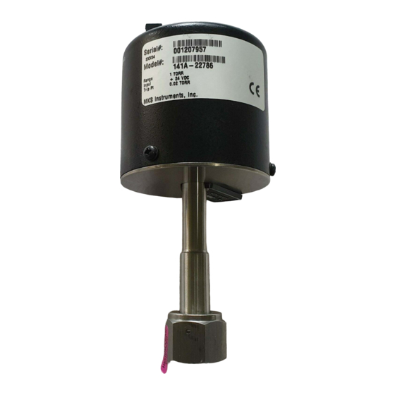
The serial number label lists the serial number and the model number of the unit. Serial #: 0123456789 Model #: 141AA00100AB MKS Instruments, Inc. Made in the USA Figure 5: Serial Number Label Note If your 141/142 unit was ordered for fail-safe operation, there will be a... - Page 34 Labels Chapter Three: Overview This page intentionally left blank.
-
Page 35: Chapter Four: Operation
Chapter Four: Operation General Information Chapter Four: Operation General Information The vacuum pressure switch should first be inspected and installed as outlined in Chapter Two: Installation, page 19. After the unit has been installed and power applied, a minimum of 15 minutes for the 141 switch and 4 hours for the 142 switch should be allowed for the unit to stabilize. -
Page 36: How To Activate Fail-Safe Operation
How To Activate Fail-Safe Operation Chapter Four: Operation How To Activate Fail-Safe Operation The pressure switch may be jumpered internally for Fail-Safe operation. In this mode the relay will be energized below the trip point instead of above. The normally open (NO) contacts will be closed and normally closed (NC) contacts will be open at pressures below the trip point. -
Page 37: Chapter Five: Maintenance
Periodically wipe down the unit with a damp cloth. Maintenance Should any difficulty be encountered in the use of this instrument, it is recommended that you contact any authorized MKS Calibration or Service Center, listed on the back cover, for repair instructions. Note... - Page 38 Maintenance Chapter Five: Maintenance This page intentionally left blank.
-
Page 39: Appendix A: Product Specifications
Appendix A: Product Specifications Electrical Specifications Appendix A: Product Specifications Electrical Specifications Power Required Type 141 +20 to +30 VDC (60 mA @ 24 VDC) Type 142 +20 to +30 VDC A 1.2 Amps. max. (875 mA @ 24 VDC) Outputs Electromechanical Relay DPDT (isolated) contacts rated up to 1 Amp @ 30... -
Page 40: Physical Specifications
Physical Specifications Appendix A: Product Specifications Physical Specifications Fittings Standard ½” (12.7 mm) tubulation Optional Swagelok 8-VCR, Mini-CF, NW-16-KF, ® Swagelok 8-VCO 5000 to 25000 Torr units are supplied with ½” diameter ports terminated with 8-VCR fittings Mechanical Outline Type 141 Refer to Figure 1, page 21. -
Page 41: Appendix B: Model Code Explanation
Appendix B: Model Code Explanation Model Code Appendix B: Model Code Explanation Model Code The options of your unit are identified in the model code. The model code is identified as follows: Type 14XA-XXXXXYZ where: Type 14XAA XXXXX Type Number Full Scale Range Fittings Relay Mode... - Page 42 Model Code Appendix B: Model Code Explanation Full Scale Range (XXXXX) The full scale range is indicated by a five-digit code. Full Scale Range Ordering Code 00001 00002 00010 00100 1000 01000 5000 05000 10000 10000 15000 15000 20000 20000 25000 25000 Fittings (Y)
-
Page 43: Index
Index Index Accuracy, 33 Operation fail-safe operation, 30 set point adjustment, 29 Cleaning, 31 Customer support, 18 Pressure Transducer Safety Information, 1 Dimensions, 21–22 Relays, 17, 24, 33, 36 Returning the product, 18, 19 Electrical, 24 Sensor, 25 Fail-safe, 17, 24, 30, 36 Serial number label, 27 Fittings, 34, 36 Set point, 17... - Page 44 Index Warm up, 29...
- Page 45 Index...
Need help?
Do you have a question about the 141A Series and is the answer not in the manual?
Questions and answers