
Subscribe to Our Youtube Channel
Summary of Contents for Arris CHP Max5000
- Page 1 CHP Max ™ Headend Optics Platform Chassis, Controllers and Power Supplies Equipment Manual 1508685 Revision D...
- Page 3 CHP Max™ Headend Optics Platform Chassis, Controllers and Power Supplies Equipment Manual 1508685 Revision D...
- Page 4 ARRIS Enterprises, Inc. (“ARRIS”). ARRIS reserves the right to revise this publication and to make changes in content from time to time without obligation on the part of ARRIS to provide notification of such revision or change.
- Page 5 Contact Technical Support when you need assistance with installed products. The ARRIS TAC Call Center provides Customer support 24/7/365. A TAC agent will create your case and escalate to the appropriate technical support team. Critical Severity 1 or 2 issues will be warm transferred for immediate assistance.
- Page 6 Repair Services Contact Repair Services if you need to return a product for repair. Please go to the ARRIS website ( ) and click the Support link and then click the Repair Services link http://www.arris.com for more information. CHP Max™ Headend Optics Platform Chassis, Controllers and Power Supplies...
-
Page 7: Table Of Contents
Local Monitoring with the CHP-CMS Craft Management Software ....1-12 CHP Max5000 Chassis (Rear Fiber Version) Chapter 2 Equipment Description ............ -
Page 8: Equipment Description
Backplane Ethernet Switch ........... 2-25 CHP Max5000 Chassis (Front Fiber Version) Chapter 3 Equipment Description . - Page 9 Input Filter ............. Power Factor Correction Circuitry .
- Page 10 ARRIS Developed MIBs........
- Page 11 ARRIS Developed MIBs........
- Page 12 CHP Max™ Headend Optics Platform Chassis, Controllers and Power Supplies 1508685 Rev D...
-
Page 13: Introduction
Craft Management Software Functions — page 1-10 Overview This Equipment Manual covers the following CHP chassis, controller and power supply modules. CHP Max5000 Chassis Rear Fiber Versions are covered in Chapter 2. ■ CHP Max5000 Chassis Front Fiber Versions are covered in Chapter 3. ■... -
Page 14: Functional Description
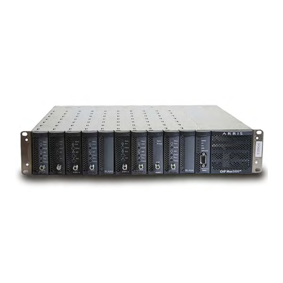
Figure 1.1 CHP Max Headend Optical Platform The CHP Max headend optical platform transmits and receives optical signals. In its base form, the platform consists of a rack-mounted chassis configured with these plug-in modules: power supply (one or two) ■ application modules (such as forward transmitters and return receivers) ■... -
Page 15: Chassis
Block Diagram Chassis The 2RU CHP Max5000 chassis mounts in a 19-inch or 23-inch rack. Each chassis holds up to 10 application modules, 2 power supply modules, and 1 management module. Modules slide into the chassis’ open front; RF and optical connections are made to the application modules installed in the chassis. -
Page 16: Management Modules
SMM-1, or SMM-2) polls the application and power supply modules installed in the chassis for status information. Both modules accommodate firmware upgrades in the field, however, such upgrades may be service affecting under certain circumstances, so ARRIS recommends performing upgrades in a service maintenance window. -
Page 17: Statements Of Compliance
Changes or modifications to this device not expressly approved by ARRIS may cause the operation of this device to violate Part 76 of CFR 47, voiding the user’s authority to operate the equipment in the domestic US. -
Page 18: Product Safety
This product conforms to the design safety criteria as detailed in IEC 60950. This criteria eliminates, or reduces hazards; appropriate labels or markings warn the user of hazards. Fiber Care and Cleaning For fiber care information, please reference the ARRIS Fiber Care and Cleaning Guide, P/N 1506507. FDA CDRH/IEC Laser Classifications... - Page 19 Optical Modules Optical Wavelength/Power Laser Class Single-input Forward Tx 1310 ±10nm radiation CHP-FTX-02 thru -11 2 thru 11dBm CHP-FTX-12 and -15 12 and 15dBm Dual-input Forward Tx 1310 ±10nm radiation CHP-FTX-D(XL)-02 thru -11 2 thru 11dBm CHP-FTX-D(XL)-12 thru -15 12 thru 15dBm 1GHz Dual-input Forward Tx 1291, 1293nm radiation CHP-SW0x-xxxx-xx-S...
-
Page 20: Tools And Equipment
Product Name (short). Anyone performing the procedures in this manual is expected to be familiar with the appropriate and safe use of these tools. CHP Max Hardware Components CHP Max5000 Chassis ■ CHP Max Power Supply ■... -
Page 21: Tools
For CENELEC compliance, install a FAIR-RITE snap-on toroid EMI suppression filter (FAIR-RITE P/N 0431164951 or ARRIS P/N 862344) supplied with the SMM on the cable connected to the Ethernet connector at the rear of the chassis. This filter should be installed as close as possible to the Ethernet connector to reduce conducted RFI. -
Page 22: Topology Manager Features
CORView Lite Element Manager Software User’s Guide (P/N 1506672). Craft Management Software Functions The CHP Max Craft Management Software provides local access to the CHP Max5000 chassis using either a serial or USB (cable P/N CHP-RS232-USB) interface between a computer and the Craft Interface connector on the front of the CMM or SMM. In addition to this local access, the Craft software also provides remote access using a cross-over Ethernet cable between a computer’s Ethernet connector and the Ethernet connector on... -
Page 23: Installing Chp Max Craft Management Software
Installing CHP Max Craft Management Software To install the CHP Max Craft Management Software ➤ Insert the CHP-CMS-1 CD-ROM. If the CD autoruns, go to Step 4. Open the Windows Explorer or any compatible file browser. Double-click the file in the main directory of the CD-ROM. setup.exe The Welcome to the Install Shield Wizard appears indicating that it will install CHP Craft software. -
Page 24: Local Monitoring With The Chp-Cms Craft Management Software
Local Monitoring with the CHP-CMS Craft Management Software To locally monitor the CHP Max Headend Optics Platform, ➤ Connect the serial cable between the CMMs (or SMMs) DB-9 Craft interface connector and the computer containing the Craft Management Software. If the software has not been installed, refer to Installing CHP Max Craft Management Software —... - Page 25 Figure 1.4 Starting Communication via Craft Terminal Click here to connect to or disconnect from the chassis. Button shown is connected. The Installed Modules window opens and indicates the communication status with color-coded arrows. – When communication is active, this window shows the modules and fans installed in the chassis.
- Page 26 Table 1.3 CHP Module Software Compatibility Module Catalog No. Current Craft CORView or Legacy Management Enterprise/ Product Software Lite (CMS “GUI”) AC and DC Power Supply Modules AC Power Supply CHP-PS/AC1 Legacy AC Power Supply with quieter CHP-PS/AC1- Current fans AC Power Supply (475 W) CHP-PS/AC1-S Current...
- Page 27 Table 1.3 CHP Module Software Compatibility Module Catalog No. Current Craft CORView or Legacy Management Enterprise/ Product Software Lite (CMS “GUI”) 1 GHz Redundant Forward CHP-GFRX-S Current Receiver Return Receiver Modules Fiber Out the Front Return CHP-1RRX-S Current Receiver Dual Return Receiver CHP-2RRX-S Current Non-Redundant Quad Return...
- Page 28 Table 1.3 CHP Module Software Compatibility Module Catalog No. Current Craft CORView or Legacy Management Enterprise/ Product Software Lite (CMS “GUI”) 1 GHz CORWave II Variable CHP-C2-MWV Current Output Transmitter (NTSC) x-16-S (x=01-16) 1 GHz CORWave II Fixed CHP-C2-MW0 Current Output Transmitter (NTSC) x-09-S (x=01-16)
- Page 29 Table 1.3 CHP Module Software Compatibility Module Catalog No. Current Craft CORView or Legacy Management Enterprise/ Product Software Lite (CMS “GUI”) 1 GHz Dual Input Fixed Output CHP-GFX-131 Legacy Forward CWDM Transmitter 1-XX-S (XX=13, 14, 15) 1 GHz Dual Input Extended CHP-GFX-D-XX Legacy Linearization Forward...
- Page 30 Table 1.3 CHP Module Software Compatibility Module Catalog No. Current Craft CORView or Legacy Management Enterprise/ Product Software Lite (CMS “GUI”) 1 GHz CORWave CHP-SF0x-129 Current Single-Density Fixed Output 1-XX-S Transmitter (XX=04, 06, 08, 10, 12, 13) 1 GHz CORWave CHP-SFVx-129 Current Single-Density Variable Output...
- Page 31 Table 1.3 CHP Module Software Compatibility Module Catalog No. Current Craft CORView or Legacy Management Enterprise/ Product Software Lite (CMS “GUI”) 1550 Erbium Doped Fiber CHP-EDFA-CG Current Amplifier (Constant -13-1-S Gain/Constant Power) CHP-EDFA-CG Current -16-1-S CHP-EDFA-CG Current -19-1-S CHP-EDFA-CG Current -22-1-S 1550 Erbium Doped Fiber CHP-EDFA-16-...
- Page 32 Table 1.3 CHP Module Software Compatibility Module Catalog No. Current Craft CORView or Legacy Management Enterprise/ Product Software Lite (CMS “GUI”) 1 GHz Single Channel Forward CHP-GAMP Legacy RF Amplifier 1 GHz 3 Input Forward RF CHP-GAMP3 Current Amplifier Optical A/B Switch Optical A/B Switch CHP-OPTSWIT Current...
-
Page 33: Chp Max5000 Chassis (Rear Fiber Version)
Backplane Ethernet Switch — page 2-25 Equipment Description The CHP Max5000 chassis mounts directly in a 19-inch rack or in a 23-inch rack using an optional bracket kit (P/N CHP-EXTBKT-23). The 2RU (3.5 in. [8.9 cm]) chassis holds up to 10 application modules, 2 power supply modules, and 1 management module. - Page 34 Newest chassis with 8 dual-speed fans for quieter operation and backplane that handles higher current loads and high speed applications such as CHP ePON OLT. ARRIS recommends using this chassis for all current and future deployments starting July 2010. CHP-CHASSIS-19S-B No longer available.
-
Page 35: Tools And Materials
A management module provides an interface between the management system and the CHP Max5000 chassis. Rear-mounted Shelf Interconnect jacks (RJ-14) permit daisy-chaining of an entire rack of CHP Max5000 chassis for remote monitoring. A terminal block provides external alarm relay for such functions as an autodialer. -
Page 36: Precautions
Keep all packing materials until your inspection is complete. When possible, save the shipping container for future reshipment and/or storage. If damage is discovered, file a claim with the carrier immediately and notify your ARRIS representative as soon as possible. Product deemed defective by the original purchaser must be returned to ARRIS prepaid in the original packing material (or equivalent) with a Return Material Authorization (RMA) from ARRIS Customer Service (800-233-2267). -
Page 37: Connectors And Additional Assemblies
Rear View - CHP-CHASSIS-19, -19Q, and -19S Low Speed Shelf Interconnect Fans (8) SNMP Interface (Ethernet) Local Alarm RF Connector Locations Terminal Block High Speed Shelf Interconnect Rear View - CHP-CHASSIS -19U Rev D CHP Max5000 Chassis (Rear Fiber Version) - Page 38 Table 2.4 CHP Max5000 Chassis Connectors and Fans Connectors Description DC/Communication Multi-pin connectors on chassis backplane carry DC power (via DC bus) Connectors and communication signals (via SPI bus) into and out of application modules. Shelf Interconnect On all models except the CHP-CHASSIS-19U, RJ-14 connectors permit “daisy-chaining”...
-
Page 39: Module Locations
System Management Module (SMM or SMM-1) — virtual slot 15 slides into this slot. Note ARRIS recommends using a 475 Watt power supply rather than a 250 Watt power supply if a chassis will be fully populated with CORWave II (CHP-C2-) transmitter modules. -
Page 40: Functional Description
Functional Description Figure 2.4 CHP Max System Please note that the contacts on the Local Alarm terminal block are reversed. Block Diagram N. C. Local Management Module Alarm Com (CMM or SMM) N. O. SNMP Ethernet Power Supply 1 RS-485 Shelf Interconnect Power Supply 2... -
Page 41: Management Signals
Management Signals Local Monitoring Craft Management Software is used to monitor a single CHP Max5000 chassis through a direct RS-232 connection to the CMM or SMM. The CMM or SMM sends management signals through the SPI bus on the chassis backplane to the other modules installed in the chassis, and status information from the modules travels back through the same route;... -
Page 42: Offset Bracket Kit Installation
Offset Bracket Kit Installation The offset bracket kit (P/N CHP-OFFBKT-19) is installed on the CHP-CHASSIS-19Q-B or CHP-CHASSIS-19S-B chassis to allow the chassis to be extended either four or six inches out from the front of the 19-inch rack. This chassis is the similar to the CHP-CHASSIS-19Q chassis except it has six holes on each side toward the front for the offset brackets. -
Page 43: Tablet Pc Installation Requirements
Refer to the system/headend map for the rack location of the CHP chassis. Align the mounting holes in each of the front flanges of the chassis with holes in the rack. Rev D CHP Max5000 Chassis (Rear Fiber Version) 2-11... - Page 44 Note The tablet PC bracket assembly (P/N 1500376-001) can NOT be installed in front of a CHP chassis with the optional handle kit (P/N CHP-HANDLE-KIT) installed. If desired, position the optional tablet PC bracket assembly (P/N 1500376-001) over the CHP chassis and align the mounting holes of the bracket with the mounting holes of the CHP chassis.
-
Page 45: Configuring The Chp Chassis
Installing a Power Supply Module Only one Power Supply module is required to operate a fully loaded chassis. Installing an additional Power Supply module improves reliability by providing load sharing and redundancy. Rev D CHP Max5000 Chassis (Rear Fiber Version) 2-13... - Page 46 ESD. Do not touch any components not specifically referred to in these instructions. CAUTION Refer to the ARRIS Fiber Care and Cleaning Guide, P/N 1506507, for important guidelines to follow when installing fiber optic cable.
- Page 47 Configuring the XMOD/GMOD on page 8-9 (CHP-XMOD-xxx-xx-x) or (CHP-GMOD-xxx-xx-xx) Dual-input Return Transmitter (CHP-RTXx-10-S-xx) Configuring the RTX on page 9-10 Erbium Doped Fiber Amplifier (EDFA) Configuring the EDFA on page 11-7 (CHP-EDFA-[CG]-xx-x-x) Rev D CHP Max5000 Chassis (Rear Fiber Version) 2-15...
- Page 48 Table 2.7 Module Configuration Reference (cont’d) Module Section Redundant Single Channel Forward Receiver Configuring the RFRX or GFRX on page 12-9 (CHP-RFRX-S) Redundant Single Channel Forward Receiver Configuring the RFRX or GFRX on page 12-9 (CHP-GFRX-S) Dual Channel Return Receiver (CHP-2RRX-S) Configuring the 2RRX on page 13-8 Redundant Dual Channel Return Receiver (CHP-R2RR-S) Configuring the R2RR on page 14-11...
- Page 49 Connect the fan power connector to the connector on the rear of the chassis. The connector is keyed so that it can only be inserted in the proper orientation. CAUTION Use extreme care to avoid pinching or damaging wires. Rev D CHP Max5000 Chassis (Rear Fiber Version) 2-17...
- Page 50 Position the wires of the power connector between the top of the fan and chassis, and then carefully push the wires toward the front of the chassis and position the power connector as shown in Figure 2.7. Observe proper fan operation with air blowing out the rear of the chassis. Repeat Steps 1 through 8 for each of the remaining seven fans, one at a time.
- Page 51 Reset Configuration – Select this function only after replacing the SMM-2 with a ■ different type of module. Do not select this function if you are replacing the SMM-2 with a different SMM-2. Figure 2.8 SMM-2 Module Properties Window Rev D CHP Max5000 Chassis (Rear Fiber Version) 2-19...
- Page 52 Figure 2.9 SMM-2 Status and Control Window Figure 2.10 SMM-2 Alarm Configuration Window Craft Management Software Functions After launching the CHP Max Craft Management Software, click on the Disconnected button or click Communication > Connect and then double-click on any of the eight fans on the rear of the chassis.
- Page 53 Saves output current data points vs. time to an Excel file format. Module Identity tab This tab only provides status. Refer to Figure 2.12 on page 2-22 to see the various module parameters. Rev D CHP Max5000 Chassis (Rear Fiber Version) 2-21...
- Page 54 Table 2.9 Controls and Functions of the Craft Management Software (cont’d) Control Function Alarms tab This tab lists all major and minor alarms as shown in Figure 2.13 on page 2-23. Figure 2.12 Chassis Fan Bay Module Identity Tab Display 2-22 CHP Max™...
- Page 55 Figure 2.14 Threshold/Alarm Diagram Alarm Threshold Major (red) Major High Minor (yellow) Minor High No Alarm (green) Minor Low Minor (yellow) Major Low Major (red) Rev D CHP Max5000 Chassis (Rear Fiber Version) 2-23...
- Page 56 The factory-default threshold and deadband values for each parameter are listed in Table 2.10. A deadband or hysteresis value prevents alarm oscillation. Once a threshold is exceeded, the alarm can only be downgraded if the parameter is at least a deadband below the threshold value.
- Page 57 The Backplane Ethernet Switch is a 10/100BaseT 2-Port Ethernet switch that provides a 100-Mbps management backplane for ePON modules and eliminates an external data cable connection. It supports a Fast Ethernet switch option for the management backplane as a built-in accessory. Rev D CHP Max5000 Chassis (Rear Fiber Version) 2-25...
- Page 58 Figure 2.16 Backplane Ethernet Switch 2-26 CHP Max™ Headend Optics Platform Chassis, Controllers and Power Supplies Rev D...
- Page 59 CHP ePON OLT. (ARRIS recommends using this chassis for all current and future deployments starting July 2010.) The speed of each dual-speed fan is determined by the ambient air temperature surrounding that fan.
- Page 60 A management module provides an interface between the management system and the CHP Max5000 chassis. Rear-mounted Shelf Interconnect jacks (RJ-14) permit daisy-chaining of an entire rack of CHP Max5000 chassis for remote monitoring. A terminal block provides external alarm relay for such functions as an autodialer.
- Page 61 Keep all packing materials until your inspection is complete. When possible, save the shipping container for future reshipment and/or storage. If damage is discovered, file a claim with the carrier immediately and notify your ARRIS representative as soon as possible. Product deemed defective by the original purchaser must be returned to ARRIS prepaid in the original packing material (or equivalent) with a Return Material Authorization (RMA) from ARRIS Customer Service.
- Page 62 Chassis Options The current CHP Max5000 recessed chassis (P/N CHP-CHASSIS-R-19U) mounts directly into a standard 19-inch rack. An optional bracket kit (P/N CHP-EXTBKT-23) is sold separately to mount the chassis in a 23-inch rack. In addition to this, an optional fiber protection kit (P/N...
- Page 63 Shelf Interconnect Rear View - CHP-CHASSIS-R-19 and -R-19Q Low Speed Shelf Interconnect Fans (8) SNMP Interface (Ethernet) Local Alarm RF Connector Locations Terminal Block High Speed Shelf Interconnect Rear View - CHP-CHASSIS -R-19U Rev D CHP Max5000 Chassis (Front Fiber Version)
- Page 64 Table 3.3 CHP Max5000 Chassis Connectors and Fans Connectors Description DC/Communication Multi-pin connectors on chassis backplane carry DC power (via DC bus) Connectors and communication signals (via SPI bus) into and out of application modules. Shelf Interconnect On all models except the CHP-CHASSIS-R-19U, RJ-14 connectors permit “daisy-chaining”...
- Page 65 Craft Management Module (CMM) or System Management Module (SMM) slides into this slot. Note ARRIS recommends using a 475 Watt power supply rather than a 250 Watt power supply if a chassis will be fully populated with CORWave II (CHP-C2-) transmitter modules.
- Page 66 Management Signals Local Monitoring Craft Management Software is used to monitor a single CHP Max5000 chassis through a direct RS-232 connection to the CMM or SMM. The CMM or SMM sends management signals through the SPI bus on the chassis backplane to the other modules installed in the chassis, and status information from the modules travels back through the same route;...
- Page 67 USB serial cable (P/N CHP-RS232-USB) for communications between the tablet PC ■ (type A male) and CMM/SMM (DB9 male). Refer to the paragraph To install the chassis to install the tablet PC bracket assembly. Rev D CHP Max5000 Chassis (Front Fiber Version)
- Page 68 CHP Chassis Installation CAUTION Some components are sensitive to electrostatic discharge (ESD)! Use a grounding strap to prevent damage to electronic components by accidental ESD. Do not touch any components not specifically referred to in these instructions. CAUTION Two people are required to install the chassis. Due to the weight of a loaded chassis, the chassis should be installed without modules.
-
Page 69: Thermal Limits For Chassis Loading
Power Supply may be installed in for improved reliability. All outputs of the Power Supply module(s) are connected using internal diodes or steering field effect transistors (FETs) with another Power Supply module. The function of the diodes or steering Rev D CHP Max5000 Chassis (Front Fiber Version) 3-11... -
Page 70: Module Installation
FET circuit is to route power from the Power Supply modules with the highest voltage to the chassis backplane. Two installed Power Supply modules will share the chassis load within 10% of each other. Module Installation After installing all of the chassis in your CHP system, you need to install modules into each of the chassis. -
Page 71: Installing An Application Module
ESD. Do not touch any components not specifically referred to in these instructions. CAUTION: Refer to the ARRIS Fiber Care and Cleaning Guide, P/N 1506507, for important guidelines to follow when installing fiber optic cable. -
Page 72: Installing The Cmm Or Smm Module
Installing the CMM or SMM Module Note Ensure that the desired Power Supply configuration is installed before installing the CMM or SMM. The Power Supply module(s) is located behind the CMM or SMM module. To install the CMM or SMM ➤... -
Page 73: Maintenance
6 and 8 in-lbs. Connect the fan power connector to the connector on the rear of the chassis. The connector is keyed so that it can only be inserted in the proper orientation. Rev D CHP Max5000 Chassis (Front Fiber Version) 3-15... -
Page 74: Corview Lite Element Manager Software Functions
CAUTION Use extreme care to avoid pinching or damaging wires. Position the wires of the power connector between the top of the fan and chassis, and then carefully push the wires toward the front of the chassis and position the power connector as shown in Figure 3.6. - Page 75 Reset Configuration – Select this function only after replacing the SMM-2 with a ■ different type of module. Do not select this function if you are replacing the SMM-2 with a different SMM-2. Figure 3.7 SMM-2 Module Properties Window Rev D CHP Max5000 Chassis (Front Fiber Version) 3-17...
-
Page 76: Craft Management Software Functions
Window Craft Management Software Functions The CHP Max Craft Management Software provides local access to the CHP Max5000 chassis using either a serial or USB (cable P/N CHP-RS232-USB) interface between a computer and the Craft Interface connector on the front of the CMM or SMM. In addition to this local access, the Craft software also provides remote access using a cross-over Ethernet cable between a computer’s Ethernet connector and the Ethernet connector on the rear of the chassis. - Page 77 CHP modules, refer to Installation of CHP Max5000 Craft Management Software on page 5-6 for instructions on installing this software. For instructions on configuring for local access to the CHP, refer to the section To configure CHP for local access via Craft software on page 7-14.
- Page 78 Table 3.6 Controls and Functions of the Craft Management Software (cont’d) Control Function Fan 1-8 Current Displays the 12V current of each of the eight chassis fans in mA. Configure Sets major low, minor low, minor high, and major high alarm limits of all eight fan currents.
-
Page 79: Setting Major And Minor Alarm Threshold Limits
Figure 3.13 Threshold/Alarm Diagram Alarm Threshold Major (red) Major High Minor (yellow) Minor High No Alarm (green) Minor Low Minor (yellow) Major Low Major (red) Rev D CHP Max5000 Chassis (Front Fiber Version) 3-21... - Page 80 The factory-default threshold and deadband values for each parameter are listed in Table 3.7. A deadband or hysteresis value prevents alarm oscillation. Once a threshold is exceeded, the alarm can only be downgraded if the parameter is at least a deadband below the threshold value.
-
Page 81: Backplane Ethernet Switch
The Backplane Ethernet Switch is a 10/100BaseT 2-Port Ethernet switch that provides a 100-Mbps management backplane for ePON modules and eliminates an external data cable connection. It supports a Fast Ethernet switch option for the management backplane as a built-in accessory. Rev D CHP Max5000 Chassis (Front Fiber Version) 3-23... - Page 82 Figure 3.15 Backplane Ethernet Switch 3-24 CHP Max™ Headend Optics Platform Chassis, Controllers and Power Supplies Rev D...
-
Page 83: Chp Max Ac Power Supply
C H A P T E R CHP MAX AC POWER SUPPLY The following table lists the minimum revision level to enable all features of this module to work properly. If you are installing a module and have a later revision, all functions are compatible unless stated otherwise in the release notes. - Page 84 The CHP Max AC power supply (P/N CHP-PS/AC1-Q-NP) is intended for international customers who cannot use the US standard power cord. No power cord is included and the customer must order the appropriate power cord separately (refer to Table 4.1 on page 4-2). Although each chassis requires only one power supply, the CHP chassis accepts two power supplies.
-
Page 85: Connectors
Connectors Figure 4.2 CHP AC Power Supply Front and Rear Views Front (no connection points or status indicators) Rear AC In DC/Communication Connector Table 4.2 Power Supply Connectors Callout Description AC Input Power Connector IEC 320-C14 power connector. Accepts AC input from 85 to 264V Fans Cooling fans. -
Page 86: Functional Description
Functional Description Figure 4.3 AC Power Supply Block Diagram IEC Connector A standard IEC connector accepts AC input. Fuse This fuse limits the current used by the Power Supply module if a short circuit occurs inside the module and prevents the loss of AC power to other connected devices. The fuse is not user-serviceable. -
Page 87: Isolation Circuitry
Isolation Circuitry The output voltage from each filter is routed through a diode or steering Field Effect Transistor (FET) that allows the use of redundant Power Supply modules. Microcontroller The microcontroller monitors the voltages, fan current, and internal temperature and communicates that information to the management module through the chassis’... -
Page 88: Craft Management Software Functions
Push the Power Supply module retaining tab to the right and slide the module out the front of the chassis. Craft Management Software Functions After launching the CHP Max Craft Management Software, click on the Disconnected button or click Communication > Connect and then double-click on the AC power supply module you want to monitor. - Page 89 Table 4.3 Controls and Functions of the Craft Management Software (cont’d) Control Function Show info Lists the four alarm thresholds, temperature units (°C or °F), and graphical display configuration information. Show history Displays a graph of temperature vs. time. °C or °F Allows you to select the temperature units (°C or °F) to display.
- Page 90 Table 4.3 Controls and Functions of the Craft Management Software (cont’d) Control Function Fan 1 current Displays fan 1 current in mA. Configure Sets major low, minor low, minor high, and major high alarm limits of fan 1 and 2 currents. Show info Lists the four alarm thresholds and graphical display configuration information.
- Page 91 Figure 4.5 AC Power Supply Module Identity Tab Display Figure 4.6 AC Power Supply Alarm Tab Display Rev D CHP Max AC Power Supply...
-
Page 92: Setting Major And Minor Alarm Threshold Limits
Setting Major and Minor Alarm Threshold Limits The alarm parameters listed in Table 4.4 have four adjustable alarm thresholds and a fixed deadband value associated with each parameter. Alarms generated by the status monitoring circuit are based on which thresholds have been exceeded. Figure 4.7 shows the four threshold levels and the corresponding alarms. - Page 93 To adjust the alarm threshold limits ➤ Follow the procedures for Local Monitoring with the CHP-CMS Craft Management Software — page 1-12. Double-click the PS module identifier in the module inventory or double-click on the desired power supply module in the image map to open that module’s management window.
-
Page 94: Updating Ac Power Supply Module Microcontroller Firmware
Method 1 To update AC power supply microcontroller firmware ➤ Obtain the appropriate firmware file through ARRIS technical support or your sales representative. Use the firmware file listed in Table 4.5 to update the firmware in a module. Table 4.5 CHP AC Power Supply Firmware Hex Files Firmware Hex File PSAC.hex... - Page 95 Ensure that the power supply module requiring the firmware download is powered Note If either an SMM-1 or CMM-1 is installed in the chassis with the power supply module requiring the firmware download, Craft Management Software GUI version 7.0.22 or later must be used. Start the Craft Management Software GUI.
- Page 96 Method 2 To update AC power supply microcontroller firmware ➤ Obtain the appropriate firmware file through ARRIS technical support or your sales representative. Use firmware file listed in Table 4.5 on page 4-12 to update the firmware in a module.
- Page 97 Start the Craft Management Software GUI. If either an SMM or CMM module is installed in the chassis with the module requiring the firmware download, go to Step 9. Double-click the CMM-1 or SMM-1 module identifier in the module inventory on the left side or double-click on the CMM-1 or SMM-1 module in the chassis image map to open the management window.
- Page 98 Note Do not abort downloading the firmware files. If the file download process is abnormally terminated, you will need to restart the download process. To do this, close the GUI and start over using the firmware file in Table 4.5 on page 4-12. Note If you encounter a problem downloading the firmware, ensure that the CMM-1 or SMM-1 module is fully inserted into the chassis.
-
Page 99: Ac Power Supply Specifications
AC Power Supply Specifications Table 4.6 CHP AC Power Supply Specifications Characteristic Specification Electrical CHP-PS/AC1-Q CHP-PS/AC1-SW Input Voltage (47 to 63 Hz) 85 to 264 V 85 to 264 V Input Current Limit, max., continuous, 6.0A 9.0A Inrush Current Limit, max., peak Input Transient 4kV/0.13kA 4kV/0.13kA... - Page 100 4-18 CHP Max™ Headend Optics Platform Chassis, Controllers and Power Supplies Rev D...
- Page 101 C H A P T E R CHP MAX DC POWER SUPPLY The following table lists the minimum revision level to enable all features of this module to work properly. If you are installing a module and have a later revision, all functions are compatible unless stated otherwise in the release notes.
-
Page 102: Equipment Description
Equipment Description Figure 5.1 DC Power Supply The CHP Max DC power supply (P/N CHP-PS/DC1) can no longer be purchased; it has been replaced by the P/N CHP-PS/DC1-Q power supply with identical specification but using a dual-speed fan to allow operation at a reduced noise level and P/N CHP-PS/DC1-SW high wattage power supply. -
Page 103: Connectors
Integrated management circuitry provides digital representations of internal temperature, input voltage, power supply output voltages, and fan current for status monitoring. Management signals enter and exit through the multi-pin connector on each power supply’s rear panel. Each CHP DC input power supply includes a power connector for the –48 V input. -
Page 104: Functional Description
Table 5.1 Power Supply Connectors Callout Description DC Input Connector Accepts DC input from –36 to –72V . Mates with a provided power plug connector (P/N MT0401). Fans Cooling fans. Two per power supply. DC/Communication Multi-pin connector. Pins carry DC voltages and communication signals Connector out of power supply and communication signals into the monitoring circuitry of the power supply. -
Page 105: Power Conversion Circuitry
Power Conversion Circuitry Power conversion circuitry produces the four isolated output voltages with the maximum load current as specified in the following table. Table 5.2 DC Power Supply Output Currents +12.0 V +5.0 V +3.5 V –5.0 V CHP-PS/DC1-Q 10 Amps 22 Amps 2.2 Amps 1.8 Amps... -
Page 106: Craft Management Software Functions
If required, remove 1/4 inch of insulation from each wire and connect the –48 V return, and ground wires to the provided power plug connector (P/N MT0401) power plug as shown in Figure 5.4 on page 5-6. Secure each wire to the power plug connector by tightening the terminal screws using a small flat-blade screwdriver. - Page 107 Figure 5.5 DC Power Supply Status and Settings Management Window Window resulting from right clicking on +12 VDC, +5 VDC, Fan 1 current, +3.3 VDC, –5 VDC, Fan 2 current, or DC Window resulting from right clicking on Internal Table 5.3 Controls and Functions of the Craft Management Software Control Function Internal Temperature...
- Page 108 Table 5.3 Controls and Functions of the Craft Management Software (cont’d) Control Function Restore Factory Settings Restores all parameters to the factory-shipped configuration. Status and Settings tab +12 VDC Displays the 12V output voltage. Configure Sets major low, minor low, minor high, and major high alarm limits. Show info Lists the four alarm thresholds and graphical display configuration information.
- Page 109 Table 5.3 Controls and Functions of the Craft Management Software (cont’d) Control Function Fan 2 current Displays fan 2 current in mA. Configure Sets major low, minor low, minor high, and major high alarm limits of fan 1 and 2 currents. Show info Lists the four alarm thresholds and graphical display configuration information.
-
Page 110: Setting Major And Minor Alarm Threshold Limits
Figure 5.7 DC Power Supply Alarm Tab Display Setting Major and Minor Alarm Threshold Limits The alarm parameters listed in Table 5.4 have four adjustable alarm thresholds and a fixed deadband value associated with each parameter. Alarms generated by the status monitoring circuit are based on which thresholds have been exceeded. - Page 111 The factory-default threshold and deadband values for each parameter are listed in Table 5.4. A deadband or hysteresis value prevents alarm oscillation. Once a threshold is exceeded, the alarm can only be downgraded if the parameter is at least a deadband below the threshold value.
- Page 112 Figure 5.9 Internal Temperature and +12V Threshold Limits Internal Temperature Alarm Threshold Settings +12V Alarm Threshold Settings Note The alarm thresholds for Fan 1 current and Fan 2 current are not independent. Changing the alarm threshold value on either of the fan meters will automatically update the alarm threshold on the other fan meter.
-
Page 113: Updating Dc Power Supply Module Microcontroller Firmware
Method 1 To update DC power supply microcontroller firmware ➤ Obtain the appropriate firmware file through ARRIS technical support or your sales representative. Use firmware file listed in Table 5.5. Table 5.5 CHP DC Power Supply Firmware Hex Files Firmware Hex File Name PSDC.hex... - Page 114 Double-click the CMM-1 or SMM-1 module identifier in the module inventory on the left side or double-click on the CMM-1 or SMM-1 module in the chassis image map to open the management window. Verify that the firmware version running on the SMM-1 or CMM-1 is 4.034 or later. If necessary, refer to Updating the CHP-CMM Microcontroller Firmware on page 5-28 to download the updated firmware into the SMM-1 or CMM-1.
- Page 115 Method 2 To update DC power supply microcontroller firmware ➤ Obtain the appropriate firmware file through ARRIS technical support or your sales representative. Use firmware file listed in Table 5.5 on page 5-13 for the appropriate module. Rev D...
- Page 116 Ensure that the power supply module requiring the firmware download is powered Note If either an SMM-1 or CMM-1 is installed in the chassis with the power supply module requiring the firmware download, Craft Management Software GUI version 7.0.15 or later must be used. Start the Craft Management Software GUI.
- Page 117 Figure 5.13 Firmware Download Method 2 10. Navigate through the Open dialog box to where the firmware file (.hex extension) for the DC power supply module is located. Note Do not abort downloading the firmware files. If the file download process is abnormally terminated, you will need to restart the download process.
-
Page 118: Dc Power Supply Specifications
DC Power Supply Specifications Table 5.6 CHP DC Power Supply Specifications Characteristic Specification CHP-PS/DC1-Q CHP-PS/DC1-SW Powering Specifications Input Voltage –72 to –36V –72 to –36V Input Current Limit, max. 12.0A @ 36V 15.0A @ 36V Inrush Current Limit, max. 40A (Note 1) 40A (Note 2) Power Consumption, max. - Page 119 Table 5.6 CHP DC Power Supply Specifications (cont’d) Characteristic Specification Regulatory Requirements (Note 4) EN 300 386 V1.4.1 EN 55022, Class B EN 55024 FCC CFR 47 Part 15 Class B ICE S-003 Issue 4 Class B UL60950 2nd Ed/CSA C22.2 number IEC 60950 and EN 60950 Notes: Inrush current shall not trip a 15A mains external circuit breaker during a Hot Start condition.
- Page 120 5-20 CHP Max™ Headend Optics Platform Chassis, Controllers and Power Supplies Rev D...
-
Page 121: Chp Max Element Management Modules Chp-Cmm, Cmm-1, Smm, And Smm-1
C H A P T E R CHP MAX ELEMENT MANAGEMENT MODULES CHP-CMM, CMM-1, SMM, AND SMM-1 This chapter describes the CHP Max Craft Management Module (CMM) and System Management Module (SMM). To obtain the status, control operation, and set the alarm limits of the application modules in a CHP chassis, the chassis must have either a CMM (P/N CHP-CMM or CHP-CMM-1) or SMM (P/N CHP-SMM, or CHP-SMM-1) management module installed. -
Page 122: Local Monitoring
Local Monitoring A computer with Craft Management Software is used to monitor a single CHP Max5000 chassis through a direct RS-232 connection to either the CMM or SMM controller module. The controller module sends management signals through the serial peripheral interface (SPI) bus on the chassis backplane to the other modules installed in the chassis, and status information from the modules travels back through the same route. -
Page 123: Operation Of Auto Config Modules
Table 6.1 Auto Config Supported Application Modules (cont’d) Application Module CMM-1 SMM-2 Firmware Firmware Revision* Revision CHP-GFXV-1291-S 4.000 2.3.0.0 CHP-GFXV-1331-S CHP-GFXV-D-xx-S/AF 4.000 2.3.0.0 CHP-GMOD-xxx-xx-xx 4.002 2.3.0.0 CHP-L2RR-S 4.032 2.3.0.0 CHP-MW0x-xxxx 4.017 2.3.0.0 CHP-MWVX-xxxx 5.004 2.3.0.0 CHP-MWXx-xxxx 5.004 2.3.0.0 CHP-OPTSWITCH 2.3.0.0 2.3.0.0 CHP-R2RR-xx CHP-SWVx... -
Page 124: Remote Monitoring
Figure 6.1 Auto-configuration States Remote Monitoring The CHP Max SMM (SNMP agent) enables monitoring and management of CHP Max equipment by communicating with an SNMP element manager with an appropriate configuration of IP addresses and management information bases (MIBs). One SMM may be used to permit remote management of the chassis containing the SMM and up to nine additional chassis with a CMM installed in each. -
Page 125: Equipment Description
DC voltage alarms at fixed time intervals, reporting that information back to the user. Note SMM or CMM firmware upgrades may be service-affecting under certain circumstances, so ARRIS strongly recommends performing upgrades in a service maintenance window. 1508685 Rev D... -
Page 126: Indicators And Connectors
Indicators and Connectors Figure 6.3 CMM/SMM Front and Rear Panels LED Status Indicators Status PS 1 PS 2 Fans Lock/Local Latch Release Local Management RS-232 Interface (DB-9F) Front View DC/Communications Connector Rear View CHP Max™ Headend Optics Platform Chassis, Controllers and Power Supplies 1508685 Rev D... - Page 127 Table 6.2 CMM and SMM/SMM-1 Connectors and Status Indicators Connector/LED Description Craft Terminal Interface RS-232 port, DB-9 connector. Connects to laptop computer with Craft Management Software installed. Note that connection to a CMM-1 is not allowed when the CMM-1 is daisy-chained to an SMM-2.
-
Page 128: Functional Description
SMM module is installed. Off = All user-set controls are unlocked and available. ■ Functional Description Figure 6.4 CHP Max Local Management and CHP Max5000 Shelf Monitoring RS-485 Shelf Interconnect Local Ethernet RJ-45 RS-232... -
Page 129: Dc Power
USB to RS-232 (P/N CHP-RS232-USB) cable between a mobile computer and the chassis' CMM. With CHP Max Craft Management Software installed on a computer, you may monitor the status of any module installed in a CHP Max5000 chassis. -
Page 130: Installation Of Chp Max Craft Management Software
ANSI/SCTE 85-2 2009 SCTE-HMS-HE-OPTICAL-RECEIVER-MIB – ANSI/SCTE 85-3 2009 SCTE-HMS-HE-OPTICAL-AMPLIFIER-MIB – ANSI/SCTE 94-1 2009 SCTE-HMS-HE-RF-AMP-MIB Supports ARRIS proprietary MIBs ■ SNMP v2/v3 compatible and complies with IETF and SCTE-HMS standards ■ Installation/Replacement of the CMM or SMM CAUTION The SMM must be installed into a chassis with a label containing CHP-CHASSIS-19 on the right front flange of the chassis. - Page 131 To install the CMM or SMM ➤ Note CMMs/SMMs manufactured after July 1, 2005 have a five digit CMM address label. This address should be used instead of the last five digits of the serial number. The CMM Address is located on a separate “CMM Address” label located just below the serial number label on all CMMs/SMMs manufactured after July 1, 2005.
-
Page 132: Management Modules Configuration
Ethernet connector on the rear of the chassis. Note For CENELEC compliance, install a FAIR-RITE snap-on toroid EMI suppression filter (FAIR-RITE P/N 0431164951 or ARRIS P/N 862344) supplied with the SMM on the cable connected to the Ethernet connector on the rear of the chassis. This filter should be installed as close as possible to the Ethernet connector to reduce conducted RFI. - Page 133 Obtain a USB-to-serial adapter cable (for example, Belkin USB to Serial F5U109 Cable). Note ARRIS recommends using the Belkin USB to Serial F5U109 Cable because it has been thoroughly tested and known to function as required. Other cables may or may not function as well.
- Page 134 Connect the USB-to-serial adapter cable to the PC’s USB port connector and the CMM-1/SMM-1 serial port connector. From the PC, select Start >Control Panel > Device Manager. The Device Manager window indicates that the USB-to-serial adapter cable is connected to a random high number COM port (for example, COM11 in Figure 6.7). Figure 6.7 Device Manager Window...
- Page 135 Figure 6.8 Advanced Settings Window 13. Click on the OK button in the Advanced Settings window. 14. Click on the OK button in the USB-to-serial adapter cable Properties window. 15. Close the Device Manager window. Connecting Chassis for Remote SNMP Monitoring Connect an IP network cable from the RJ-45 Ethernet connector (standard CPE) on the rear of each chassis containing the SMM to a remote management system.
- Page 136 Figure 6.9 Connecting Chassis for Remote SNMP Monitoring 6-16 CHP Max™ Headend Optics Platform Chassis, Controllers and Power Supplies 1508685 Rev D...
- Page 137 Install a terminator (P/N CHP-XCT-TER) in each unused Shelf Interconnect connector at the beginning and end of the daisy-chain. To set SMM IP addresses ➤ Note The CHP network cabling must be connected before setting the SMM addresses. Note To connect with the SMM, your PC network address must be a different address than the default SMM IP address (192.168.1.1) but on the same subnet mask.
- Page 138 Figure 6.11 Available Commands via the Help Window Note To connect with the SMM, your PC network address must be a different address than the default SMM IP address (192.168.1.1). Temporarily set the IP address of your PC within the range of 192.168.1.2 to 192.168.1.254. Obtain the correct IP address from your network administrator.
- Page 139 For your PC to communicate with the new SMM IP address, change the PC’s IP address so that the first three segments of the PC’s IP address are identical to the new SMM IP address and the last segment is different than the new SMM IP address. The subnet mask of the PC needs to be changed to match the subnet mask of the SMM.
- Page 140 Note It is not necessary to use the shelfadd command on a new SMM. A new SMM module’s CMM address will automatically appear as a daisy-chained shelf using telnet. Type shelfadd followed by the CMM address and press Enter. For example, type shelfadd 9742 and press Enter to add the CMM or SMM with a CMM address of 9742.
- Page 141 Figure 6.13 Shelf Command Listing Example CMM Address — Address of CMM or SMM module. Modules manufactured on or after 7-1-2005 have a 5 digit CMM Address label on the CMM or SMM module. Shelf Index Number — Used with the shelfrem command to remove a shelf. Type “shelfrem 2”...
- Page 142 Push and remove the seven push pins securing the front left plastic cover to the circuit card from the left side of the module. Referring to Figure 6.14, set DIP switch #1 to the ON position to force the SMM to use the default SMM IP address of 192.168.1.1.
-
Page 143: Resetting The Password
Resetting the Password The password command is used to change the password. However, if you forget the password, perform the following procedure on the SMM to reset the password to the default password. To reset the password ➤ Press upward on the latch release (see Figure 6.3 on page 6-6) on the front panel of the SMM and slide the module out the front of the chassis. - Page 144 Figure 6.15 CMM or SMM Status and Settings Management Window Window resulting from right clicking on +5 VDC, –5 VDC, +12 VDC, or +3.3 Window resulting from right clicking on Internal Table 6.3 Controls and Functions of the Craft Management Software Control Function Internal Temperature...
- Page 145 Table 6.3 Controls and Functions of the Craft Management Software (cont’d) Control Function Status and Settings tab Operational Status Displays a color-coded status of the 10 application module slots, 8 chassis fans (fan bay), and 2 power supplies (PS1 and PS2). Color coding is as follows: Dark grey = Device operating properly ■...
- Page 146 Table 6.3 Controls and Functions of the Craft Management Software (cont’d) Control Function When this radio button is selected, the auto-configuration mode is enabled. When this radio button is selected, the auto-configuration mode is disabled. Factory shipped with auto-configuration disabled. Enable Manual Status Unlock When this radio button is selected, the Local Control radio button on each...
- Page 147 Figure 6.16 CMM or SMM Module Identity Tab Display Figure 6.17 CMM or SMM Alarm Tab Display 1508685 Rev D CHP Max Element Management Modules CHP-CMM, CMM-1, SMM, and SMM-1 6-27...
-
Page 148: Setting Major And Minor Alarm Threshold Limits
Setting Major and Minor Alarm Threshold Limits The alarm parameters listed in Table 6.4 have four adjustable alarm thresholds and a fixed deadband value associated with each parameter. Alarms generated by the status monitoring circuit are based on which thresholds have been exceeded. Figure 6.18 shows the four threshold levels and the corresponding alarms. -
Page 149: Updating The Chp-Cmm Microcontroller Firmware
Method 1 To update CMM microcontroller firmware ➤ Obtain the appropriate firmware file through ARRIS technical support or your sales representative. Use firmware file(s) listed in Table 6.5 to update the firmware in a module. 1508685 Rev D... - Page 150 Table 6.5 CHP Firmware Hex Files Module Firmware Hex File Name CHP-CMM CMM.hex CHP-SMM CHP-CMM-1 CMM-1.hex CHP-SMM-1 Ensure that the chassis containing the module requiring the firmware download is powered up. Note If either an SMM-1 or CMM-1 is installed in the chassis with the power supply module requiring the firmware download, Craft Management Software GUI version 7.0.15 or later must be used.
- Page 151 Figure 6.20 Firmware Download Method 1 Double-click the module that is to receive the firmware update. Figure 6.21 Module Selection New firmware is downloaded to the highlighted module. The number following CMM-1 represents the CMM address. 10. Navigate through the Open dialog box to where the module’s firmware file (.hex extension) is located.
-
Page 152: Method 2
To update CMM microcontroller firmware ➤ Obtain the appropriate firmware file through ARRIS technical support or your sales representative. Use firmware file listed in Table 6.5 on page 6-30. Ensure that the power supply module requiring the firmware download is powered... - Page 153 Figure 6.22 Firmware Download Method 2 Navigate through the Open dialog box to where the firmware file (.hex extension) for the module is located. Note If you encounter a problem downloading the firmware, ensure that the CMM-1 or SMM-1 module is fully inserted into the chassis. If the problem still exists, replace the CMM-1 or SMM-1 with a spare module to verify if the originally installed CMM-1 or SMM-1 is working properly.
-
Page 154: Updating The Smm, Smm-1 Firmware
System release files in a directory as shown in Figure 6.24 on page 6-35. The directory name can be any name, but ARRIS strongly recommends using the system release numbers located on the latest CHP System CD to ensure using the correct files. -
Page 155: Using Ftp To Download The Smm Images
SNMP packets. SMM Firmware version 1.8.0.0 only provides the files for use with FTP. If you must perform an SNMP download, contact a ARRIS representative for instructions, or reference the Omni2000 manual. - Page 156 Figure 6.26 SMM File Directory As shown in the following window, type the ftp command followed by the IP address of your SMM module. The SMM will show that the FTP session is connected. Figure 6.27 SMM FTP Session The FTP session user name is CCOR, and the default password is CCOR. The FTP password is the same password used for a Telnet session and can be changed using the Telnet password command.
- Page 157 Figure 6.28 FTP Transfer Complete Message FTP Failures Bad file name: The SMM version 1.1 software requires that the file names of the Images transferred be SMMImage1.S19 and SMMImage2.S19. It will not allow any other file name to be downloaded. The error message shown by the FTP session will report: 500 Requested download not completed, bad file ■...
-
Page 158: Verify Image 1
SNMP packets were thrown away, or the download window is not set up correctly. If Image 1 cannot be downloaded on the SMM module at all, contact ARRIS technical support (see page 0) before attempting to download to Image 2. -
Page 159: Downloading Image 2
MIBs ARRIS Developed MIBs The SMM monitors both enterprise and standard MIB objects for all modules. The ARRIS developed MIBs are listed in Table A.12, ARRIS Developed MIBs — page A-11. The chp-MAX5000-TC.MIB must be loaded first and the remaining MIBs can be loaded in any order. -
Page 160: Chp Snmp Management
CMM address. To get general information about the status of a CHP chassis you need to parse in the ARRIS Common MIB file. The ARRIS common shelf MIB is indexed by the factory configured CMM address. This address can be found by reading the Entity MIB physical table. -
Page 161: Transmitter, Receiver, And Amplifier Module Slots
Transmitter, Receiver, and Amplifier Module Slots Table 6.7 Slot-Hardware-MIB Associations for Application Module Slots 01 through 10 CHP Shelf Possible Supported IETF Supported HMS Supported ARRIS Virtual Hardware Objects Objects Objects Slot index Types Slots Transmitter entPhysicalTable heCommonTable chpCommonMIB 01 to 10... -
Page 162: Power Supply And Fan Module Slots
Power Supply and Fan Module Slots Table 6.8 Slot-Hardware-MIB Associations for Power Supply (slots 11 and 12) and Fan Bay (slot CHP Shelf Possible Supported IETF Supported HMS Supported ARRIS Virtual Slot Hardware Objects Objects Objects index Types Slots DC Power... -
Page 163: Chp Trap Information
SNMP Configuration and Operations Manager Setup Load the required MIBs based on the type of modules in your system. Configure the Manager to communicate to set the IP address of the SNMP agent. ARRIS recommends using CORView Element Manager Software. NMS Operations Element management is achieved by a customer-provided NMS using a third-party SNMP manager package. - Page 164 All SNMP traps are HMS enterprise traps based on the SCTE-HMS standard. The trap variables that are supported by the SCTE-HMS-HE-COMMON-MIB (ANSI/SCTE 84-1 2003) file have been extended and ARRIS is including a chpHeadendCommon.MIB MIB that includes three trap variables in addition to the trap variables supported by the HMS standard. The HMS standard uses one trap (OID of 1.3.6.1.4.1.5591.1.1.0) and its variable bindings contain...
-
Page 165: Smm-1 Cli V3Tables Command
entConfigChange ■ hmsDownloadStatus ■ coldStart ■ warmStart ■ authenticationFailure ■ SMM-1 CLI v3tables Command The CLI command v3tables restores the default SNMP tables. This is command can be used if for any reason the SNMP tables have been changed or corrupted and a user can no longer access the SMM-1 via SNMP. -
Page 166: Cmm/Smm Specifications
CMM/SMM Specifications Table 6.11 CHP-CMM/SMM Specifications Characteristic Specification Electrical RS-232 38.4kbps RS-485 (Shelf Interconnect 38.4kbps Craft Interface Port RS-232 RS-232 debugging port (SMM only) 19.2kbps RJ-45 Ethernet 10/100Mbps Serial Peripheral Interface Bus 480kbps Power 1.2W 2.5W Connectors Craft Interface Port (RS-232) DB-9 female Mechanical Dimensions (W x H x D) -
Page 167: System Management Module 2 (Smm-2)
C H A P T E R SYSTEM MANAGEMENT MODULE 2 (SMM-2) This chapter describes the CHP Max System Management Module 2 (SMM-2). Overview — page 5-1 Auto Config — page 5-3 Equipment Description — page 5-8 Indicators and Connectors — page 5-9 Functional Description —... -
Page 168: Security
■ Local Monitoring A computer is used to monitor a single CHP Max5000 chassis through a direct USB connection to the SMM-2 controller module or direct connection to the backplane Ethernet port. The controller module sends management signals through the chassis backplane to the other modules installed in the chassis, and status information from the modules travels back CHP Max™... -
Page 169: Auto Config
Auto Config on the 10 application modules or the redundant power supplies in a shelf. In August 2006, ARRIS released the Auto Config version of CMM (P/N CHP-CMM-1) and SMM (P/N CHP-SMM-1) modules. These new management modules contain a large flash memory to store the configurable parameters such as alarm thresholds, optical output power, RF attenuator, etc., based on slot location for each of the 10 application modules and power... - Page 170 Table 7.1 Auto Config Supported Application Modules (cont’d) Application Module First Supported Firmware Version CHP-C2-MWVX latest 2.4.0.0 supported CHP-D2RRX latest 2.4.0.0 supported CHP-DDxV latest 4.000 2.6.0.0 CHP-DDxX latest 4.000 2.6.0.0 CHP-DWVX latest 2.4.0.0 supported CHP-DWXX latest 2.4.0.0 supported CHP-EDFA-HG latest 2.4.0.0 supported CHP-EDFA-PG...
- Page 171 Table 7.1 Auto Config Supported Application Modules (cont’d) Application Module First Supported Firmware Version CHP-MW0x 2.015 4.020 2.3.0.0 CHP-MWVx 2.006 4.024 2.4.0.0 CHP-MWXx 2.006 4.024 2.4.0.0 CHP-OPM1 latest supported supported CHP-OPTSWITCH latest 2.3.0.0 supported CHP-R2RR 2.000 4.000 2.3.0.0 CHP-R2RRFF latest 2.4.0.0 supported CHP-R2RRXF...
- Page 172 Monitoring — The steady state the management module enters when the shelf is ■ operating at its baseline configuration and configuration parameters change infrequently or not at all. The application modules will be polled every 5 minutes. Event Handling — State the management module enters when a module is removed ■...
-
Page 173: Remote Monitoring
Figure 7.1 Auto-configuration States Remote Monitoring The CHP Max SMM-2 (SNMP agent) enables monitoring and management of CHP Max equipment by communicating with an SNMP element manager with an appropriate configuration of IP addresses and management information bases (MIBs). Management signals enter the SMM-2 module through the Ethernet port on the chassis rear panel (refer to Figure 1.2 on page 1-5). -
Page 174: Equipment Description
DC voltage alarms at fixed time intervals, reporting that information back to the user. Note SMM-2 firmware upgrades of application modules may be service-affecting under certain circumstances, so ARRIS strongly recommends performing upgrades in a service maintenance window. CHP Max™ Headend Optics Platform Chassis, Controllers and Power Supplies... -
Page 175: Indicators And Connectors
In order to use the SMM-2 mini-USB front panel connector, the computer connected to the mini-USB connector must have special drivers installed in its operating system. Those drivers are contained in the drivers directory on the CD-ROM for CHP Max5000 System. Rear Panel Connector DC / Communication Multi-pin connector. - Page 176 Table 7.2 SMM-2 Connectors and Status Indicators Connector/LED Description PS 1 & PS 2 LEDs Indicates the status of the power supply installed in slot PS 1 or PS 2 slot, respectively. Solid Green = All internal functions operating within set limits. ■...
-
Page 177: Functional Description
Functional Description Figure 7.4 CHP Max Local Management and Monitoring Communication Signals USB between Command Line Interface The Command Line Interface (CLI) used on a computer connected to the SMM-2 mini-USB connector, sends requests for information to the SMM-2. The SMM-2 returns information received from application modules back through the USB interface port for accessing through the CLI. -
Page 178: Dc Power
Unpack and remove the module from the shipping box. Return the packing material to the shipping container, and save it for future use. Verify that you have received the item shown on the packing material list. If any item is missing or damaged, contact your ARRIS representative or reseller for instructions. -
Page 179: Telnet Connection Instructions
Note In CHP System version 4.10 or later, the IP address of Ethernet over USB mode is assigned (10.10.10.1) as the default and can be configured or changed. The SMM-2 management network must not be in the same subnet as the default IP address for the USB Ethernet mode to work. - Page 180 Figure 7.5 Laptop Computer to CHP Chassis Ethernet Connection Open a Command Prompt window and type telnet 192.168.1.1, then press the Enter key. At the login prompt, type admin, then press the Enter key. At the password prompt, type admin, then press the key.
-
Page 181: Usb Mode Connection Instructions
Press the Enter key after the all of the network information is complete For example, set interfaces eth0 10.113.130.110 mask 255.255.255.0 gateway 10.113.130.254 would be a complete entry, whereas just set interfaces eth0 10.113.130.110 would not be a complete entry. At the admin@192.168.1.1% prompt, type commit and press the Enter key. - Page 182 Figure 7.6 SMM-2 to Computer Connection After the SMM-2 is connected to the laptop computer, the OS will automatically search for the RNDIS Ethernet driver. After it fails to find the driver, the computer displays a message indicating that the driver is missing. To install the driver refer to the instructions below for your computer’s operating system (Windows 7, 8 or XP).
- Page 183 Figure 7.7 Computer Management Window When prompted to choose how to search for device driver software, select Browse my computer for driver software (refer to Figure 5.8). Rev D System Management Module 2 (SMM-2) 7-17...
- Page 184 Figure 7.8 How to Search Window When “Browse for driver software on your computer” window appears, select Let me pick from a list of device drivers on my computer, then click on the Next button (refer to Figure 5.9). Figure 7.9 Browse for Software Window When a window appears asking to select the device type, select Network adapters,...
- Page 185 Figure 7.10 Select Device Type Window When the Select Network Adapter window appears, from the Manufacturer list select Microsoft Corporation for computers running Windows 7 or select Microsoft for computers running Windows 8, then select Remote NDIS Compatible Device from the Network Adapter list and click on the Next button (refer to Figure 5.11). Figure 7.11 Select Network Adapter Window...
- Page 186 When the “Windows has successfully updated your driver software” message appears, the RNDIS driver has been installed. Click on the Close button (refer to Figure 5.12). Figure 7.12 Successful Driver Software Update Window 10. After the USB Ethernet/RNDIS Gadget’s successful installation, the Gadget now appears under Network adapters in the Device Manager window (refer to Figure 5.13).
- Page 187 Figure 7.13 Device Manager Window After Successful USB Ethernet/RNDIS Gadget Installation 11. Select Start > Control Panel. 12. When the Control Panel window appears, click on the Network and Sharing Center. 13. When the Network and Sharing Center window appears, click on Change adapter settings in the left sidebar (refer to Figure 5.14).
- Page 188 Figure 7.14 Network and Sharing Center Window 14. When the next Network and Sharing Center window appears, click on Local Area Connection labeled “Unidentified network, RNDIS/Ethernet Gadget.” In this example, it happens to be Local Area Connection 2, but that number may be different on other computers (refer to Figure 5.15).
- Page 189 Figure 7.16 Local Area Connection Status Window 16. When the Local Area Connection 2 Properties window appears, click on Internet Protocol Version 4 (TCP/IPv4) (refer to Figure 5.17). Figure 7.17 Local Area Connection 2 Properties Window 17. When the next Internet Protocol Version 4 (TCP/IPv4) Properties window appears, click on the Use the following IP address: option, then type the following addresses into the following fields (refer to Figure 5.18): Rev D...
- Page 190 – IP address: 10.10.10.5 – Subnet mask: 255.255.255.0 – Default gateway: 10.10.10.1 Figure 7.18 Internet Protocol Version 4 (TCP/IPv4) Properties Window 18. Click on the OK button. Now you can use any telnet software (for example, PuTTY) to communicate via telnet with the SMM-2.
- Page 191 Figure 7.19 Found New Hardware Wizard Window When the next Found New Hardware Wizard window appears, select the Install from a list or specific location (Advanced) option (refer to Figure 5.20). Figure 7.20 Found New Hardware Wizard Window for RNDIS/Ethernet Gadget Installation When the next Found New Hardware Wizard window appears (refer to Figure 5.21), select the Search for the best driver in these locations option.
- Page 192 Figure 7.21 Choose Search and Installation Options The wizard searches, then installs the driver. When the Found New Hardware Wizard window indicates that it “has finished installing the software for: USB Ethernet/RNDIS gadget,” click on the Finish button (refer to Figure 5.22). Figure 7.22 Completing the Found New...
- Page 193 Figure 7.23 Network Connections Window When the Local Area Connection Properties window appears, click on Internet Protocol (TCP/IP) (refer to Figure 5.24). Figure 7.24 Local Area Connection Properties Window Rev D System Management Module 2 (SMM-2) 7-27...
- Page 194 10. When the next Internet Protocol (TCP/IP) Properties window appears, click on the Use the following IP address: option, then type the following addresses into the following fields (refer to Figure 5.25): – IP address: 10.10.10.5 – Subnet mask: 255.255.255.0 –...
- Page 195 Press the Enter key after the all of the network information is complete For example, set interfaces eth0 10.113.130.110 mask 255.255.255.0 gateway 10.113.130.254 would be a complete entry, whereas just set interfaces eth0 10.113.130.110 would not be a complete entry. At the admin@192.168.1.1% prompt, type commit and press the Enter key.
- Page 196 At the command prompt, type commit. At the command prompt, type reboot. Wait for the SMM-2 to initialize. Note To change the USB connection mode to Ethernet, replace "serial" with "ethernet" in step 2 and proceed with the remaining steps listed above. SMM-2 Serial Mode Connection From a laptop computer USB port, connect a standard USB 2.0 A Male to Mini-B 5-pin Male cable of any length to the SMM-2, as shown in Figure 7.5.
- Page 197 Figure 7.27 Device Manager Window Press the Enter key and a login prompt will appear in the PuTTY terminal for logging into the SMM-2. At the login prompt, type admin, then press the Enter key. At the password prompt, type admin, then press the Enter key. To set the network information, proceed as follows: After login, at the admin@192.168.1.1>...
-
Page 198: Add Smm-2 To Corview's Monitored Devices
For example, set interfaces eth0 10.113.130.110 mask 255.255.255.0 gateway 10.113.130.254 would be a complete entry, whereas just set interfaces eth0 10.113.130.110 would not be a complete entry. At the admin@192.168.1.1% prompt, type commit and press the Enter key. The SMM-2 will log you off the system and when you log back on, the admin@10.113.130.110 >... - Page 199 Figure 7.28 Add CHPMax5000 Device Window Rev D System Management Module 2 (SMM-2) 7-33...
-
Page 200: Cli Commands
CLI Commands You can utilize the CLI commands to view and change various aspects of the CHP Chassis (refer to Figure 5.29). Figure 7.29 Top Level CLI Commands (>) Figure 5.30 lists the CLI commands that may be automatically invoked by just typing the first letter of the command. - Page 201 Figure 7.30 Configuration Level CLI Commands (%) Note The following commands are administrator group command, except for the Help command, which may be used by all users. IP Address To set the IP address, proceed as follows: After login, at the admin@192.168.1.1> prompt, type configure and press the Enter key.
- Page 202 – system to modify the SNMP system MIB variables. – trap-dest to add an SNMP trap destination. Press the Enter key after the SNMP command string is complete with its options. To set NTP (Network Time Protocol), proceed as follows: After login, at the admin@192.168.1.1>...
- Page 203 – 9 Indian Ocean – 10 Pacific Ocean – 11 Quit without modifying time zone Type the number corresponding to the time zone and press the Enter key to refine your selection. Hostname To set the hostname, proceed as follows: After login, at the admin@192.168.1.1>...
- Page 204 Delete User To delete users, proceed as follows: After login, at the admin@192.168.1.1> prompt, type configure and press the Enter key. At the admin@192.168.1.1% prompt, type delete user and press the <TAB> or <SPACE>? key to view the available Delete User command options. Press the Enter key after the Delete User command string is complete with its options.
- Page 205 At the admin@192.168.1.1% prompt, type commit and press the Enter key. Help Typing help followed by a command, displays a brief description of that command. For example, typing help ping displays a description of the ping command. Basic Commands Related to MIBs Figure 5.31 displays the basic commands related to the ENTITY-MIB of the SMM-2 The following three windows display some of the basic commands related to the SMM-2 MIBs.
- Page 206 Figure 7.31 Basic Commands Related to ENTITY-MIB 7-40 CHP Max™ Headend Optics Platform Chassis, Controllers and Power Supplies Rev D...
-
Page 207: Mibs
MIBs ARRIS Developed MIBs The SMM-2 monitors both enterprise and standard MIB objects for all modules. The ARRIS developed MIBs are listed in Table A.12, ARRIS Developed MIBs — page A-11. The CHPMAX5000-TC.mib must be loaded first and the remaining MIBs can be loaded in any order. -
Page 208: Common Mib Operation
(CMM-1 shelf address). To get general information about the status of a CHP chassis you need to parse in the ARRIS Common MIB file. The ARRIS common shelf MIB is indexed by the factory configured SMM-2 address. This address can be found by reading the Entity MIB physical table. -
Page 209: Chp Chassis/Slot Management
MIBs for the transmitters (SCTE-HMS-HE-OPTICAL-TRANSMITTER-MIB) and receivers (SCTE-HMS-HE-OPTICAL-RECEIVER) should be parsed in. To manage the general slot status the ARRIS Common MIB can be used and is indexed by the physical entity MIB index, which is determined by combining the factory configured SMM-2 shelf address and the specific slot address. -
Page 210: Chp Trap Information
Power Supply and Fan Module Slots Table 7.4 Slot-Hardware-MIB Associations for Power Supply (slots 11 and 12) and Fan Bay (slot CHP Shelf Possible Supported IETF Supported HMS Supported ARRIS Virtual Slot Hardware Objects Objects Objects index Types Slots DC Power... -
Page 211: Snmp Configuration And Operation
SNMP Configuration and Operation Manager Setup Load the required MIBs based on the type of modules in your system. Configure the Manager to communicate to set the IP address of the SNMP agent. ARRIS recommends using CORView Element Manager Software. NMS Operations Element management is achieved by a customer-provided NMS using the ARRIS or a third-party SNMP manager package. - Page 212 Table 7.6 Description of HMS Trap (heCommonAlarmEvent OID Name Variable Type Description heCommonLogTime DateAndTime This is the time when the alarm change for the object occurred. heCommonLogText DisplayString This is a text field describing the alarm. This field could be a zero length string in certain agent implementations.
- Page 213 The Active Alarms panel, which is located in the lower right section of the CORView ■ Element Manager Window (refer to Figure 5.35) lists the number of active alarms in the upper right corner of the panel and provides the following information in tabular format regarding the various alarms associated with the units installed in the device currently selected in the Device List/Tree View panel: –...
-
Page 214: Operational Guidelines
The Network Alarms panel, which is located in the lower left corner of the CORView ■ Element Manager Window (refer to Figure 5.35), graphically represents the number of current major and minor network alarms reported to CORView. A red bar represents the major alarms and a yellow bar represents the minor alarms. -
Page 215: Smm-2 Specifications
Type configure (to enter the CLI configuration mode). Type set CHPMAX5000-MIB chpMaxShelves chpAllow. At the admin@smm-2_ip_address% prompt, type commit From any PC, open a DOS command tool window (select Start > Run and type cmd) to initiate an FTP command. Most systems have the function to FTP files from the computer to another device on the Local Network. - Page 216 Table 7.7 SMM-2 Specifications Characteristic Specification Mini-USB USB 2.0 Mechanical Dimensions (W x H x D) 4.5 x 3.4 x 16.75 in. (11.4 x 8.6 x 42.5 cm) Weight 24 oz. (680 g) Environmental Operational Temperature 32 to 122 F (0 to 50 C) Specifications subject to change without notice 7-50 CHP Max™...
-
Page 217: Chp Max Monitorable Attributes
CHP Max parameters can be monitored by accessing MIB objects via the SMM module's SNMP Agent. The proprietary ARRIS MIB files are on the released CHP System CD or can be downloaded from the ARRIS support web site. The MIB type indicates if the attribute is ARRIS proprietary (ENTERPRISE) or if the attribute is contained in one of the standard IETF or standard SCTE HMS MIBs supported by the CHP Max. - Page 218 Table A.2 CMM(-1)/SMM(-1) Parameters (cont’d) Attribute Parameter MIB Object MIB Type Status AlarmBytes cmmStatusCmmAlarms ENTERPRISE RelayEnableStatus and State cmmControlRelayTrigger ENTERPRISE cmmStatusRelay ENTERPRISE Front Panel Shelf Status cmmControlShelf ENTERPRISE Shelf Status cmmStatusShelfAlarms ENTERPRISE Module Alarm Info cmmStatusShelfAlarms ENTERPRISE CraftStatus cmmStatusCraft ENTERPRISE Reset Cause chpSlotStatusModuleResetCause ENTERPRISE...
- Page 219 Table A.3 C2-MW0X and C2-MWVX Parameters Attribute Parameter MIB Object MIB Type RF Gain Major Low tx2RfConfigGain ENTERPRISE Minor Low Minor High Major High Gain Actual Major Low tx2RfConfigGainActual ENTERPRISE Minor Low Minor High Major High Laser Drive Major Low tx2RfConfigLaserDriveActual ENTERPRISE Actual...
- Page 220 Table A.4 CHP-FTX(-XL)/CHP-FTX-D(XL)/CHP-GFXF-D/CHP-GFX-D(XL)/CHP-GFXV-D/ CHP-GFXV-1291/CHP-GQTX/CHP-XMOD/CHP-GMOD/CHP-RTX3/CHP-RTX5 Parameters Attribute Parameter MIB Object MIB Type Module Serial Number entPhysicalSerialNum STANDARD Identification Production Date chpSlotConfigModuleProductDat ENTERPRISE Firmware Version STANDARD entPhysicalSoftwareRev Hardware Version STANDARD entPhysicalHardwareRev Wavelength STANDARD heOpTxLaserWavelength LaserType STANDARD heOpTxLaserType ServiceTrackingNumber ENTERPRISE chpSlotStatusModuleServiceNu Monitorable Optical Power heOpTxLaserOutputPower STANDARD Parameters...
- Page 221 Table A.5 D2RRX Parameters Attribute Parameter MIB Object MIB Type Rx1 Optical Major Low heOpRxInputPower ENTERPRISE Input Power Minor Low Minor High Major High Discrete Alarms Optical Data Major rx2StatusOpticalData ENTERPRISE Status is Corrupt Table A.6 CHP-RFRX/CHP-GFRX/CHP-2RRX/CHP-R2RR/CHP-D1RRX/CHP-L2RR Parameters Attribute Parameter MIB Object MIB Type Module...
- Page 222 Table A.6 CHP-RFRX/CHP-GFRX/CHP-2RRX/CHP-R2RR/CHP-D1RRX/CHP-L2RR Parameters Attribute Parameter MIB Object MIB Type Alarm Enable AlarmEnable can alarmEnable STANDARD States enabled/disabled for the following alarms: Major Low, Minor Low, Minor High, Major High. Deadbands Deadbands may be set for each analogAlarmDeadband STANDARD monitorable parameter. Firmware Boot Version entPhysicalFirmwareRev...
- Page 223 Table A.7 CHP-EDFA/CHP-EDFA-CG Parameters Attribute Parameter MIB Object MIB Type Module Serial Number entPhysicalSerialNum STANDARD Identification Date of Production chpSlotConfigModuleProductDat ENTERPRISE Firmware Revision STANDARD entPhysicalSoftwareRev Hardware Revision STANDARD entPhysicalHardwareRev Pump Laser Type STANDARD heOpAmpLaserType ServiceTrackingNumber ENTERPRISE chpSlotStatusModuleServiceNu Monitorable Internal Temperature heCommonTemperature STANDARD Parameters...
- Page 224 Table A.8 GAMP/GAMP3 Parameters Attribute Parameter MIB Object MIB Type Module Serial Number entPhysicalSerialNum STANDARD Identification Date Of Production chpSlotConfigModuleProductDat ENTERPRISE Firmware Revision STANDARD entPhysicalSoftwareRev Hardware Revision STANDARD entPhysicalHardwareRev Service Tracking Number ENTERPRISE chpSlotStatusModuleServiceNu Monitorable Internal Temperature heCommonTemperature STANDARD Parameters RF Gain chpRFAmpGain ENTERPRISE...
- Page 225 Table A.9 Power Supply Parameters Attribute Parameter MIB Object MIB Type Module Serial Number entPhysicalSerialNum STANDARD Identification Production Date chpSlotConfigModuleProductDat ENTERPRISE Firmware Version STANDARD entPhysicalSoftwareRev Hardware Version STANDARD entPhysicalHardwareRev Main Power DC STANDARD hePsUnitVoltageIn Main Power AC STANDARD hePsUnitVoltageIn ServiceTrackingNumber ENTERPRISE chpSlotStatusModuleServiceNu Monitorable...
- Page 226 Table A.10 Fan Parameters Attribute Parameter MIB Object MIB Type Module Hardware Version entPhysicalHardwareRev STANDARD Identification ServiceTrackingNumber chpSlotStatusModuleServiceNu ENTERPRISE Monitorable The response shall be in the heFanStatusCurrent STANDARD Parameters following order: Fan 1, 2, 3, 4, 5, 6, 7, 8 Status Alarm Bytes cmmStatusFanAlarms...
-
Page 227: Arris Developed Mibs
ARRIS Developed MIBs The management module monitors both enterprise and standard MIB objects for all modules. The ARRIS developed MIBs are listed in Table A.12. The chpCommon.mib must be loaded first and the remaining MIBs can be loaded in any order. - Page 228 Table A.12 ARRIS Developed MIBs (cont’d) ARRIS Part MIB File Name MIB Structures/ Description Number Tables Supported 1504158-003 SCTE-HMS-PROPERTY- propertyMib SCTE-HMS-PROPERTY-MIB.mib MIB.mib propertyTable provides additional information currentAlarmTable regarding the timestamp of discretePropertyTable active alarms. 1506581-002 CHPEPON-MIB eponConfigurationTable CHPEPON-MIB contains proprietary ARRIS information to...
-
Page 229: Common Mib Operation
Table A.12 ARRIS Developed MIBs (cont’d) ARRIS Part MIB File Name MIB Structures/ Description Number Tables Supported 1506970 ARRIS-FIBERNODE-MIB. nodeEntityTable ARRIS-FIBERNODE-MIB.mib contains proprietary ARRIS nodeStatusTable information to manage nodeConfigTable Fibernodes connected to a nodeSlotStatusTable CHP-D2RRX-xx-xx-S within a CHP nodeSlotStatusTable chassis managed by SMM-2 nodeRxStatusTable controller card. -
Page 230: Standard Mibs
Telnet, the chassis is automatically discovered within 20 seconds. Standard MIBs ARRIS recommends using CORView Element Manager Software to monitor, archive, and analyze data retrieved from SNMP Agents. This browser supports SCTE's (Society of Cable and Telecommunications Engineers) HMS standard for the SNMP monitoring and management of inside and outside HFC cable plants. - Page 231 Table A.14 Standard HMS MIBs (cont’d) MIB Name Description ANSI/SCTE 38-1 2009 Hybrid Fiber/Coax Outside Plant Status Monitoring SCTE-HMS-PROPERTY-MIB (formerly HMS 026) Management Information Base (MIB) Definition http://www.scte.org/documents/pdf/standards/ANSI_SCTE%2038-1%202009.p http://www.scte.org/documents/standards/approved/hms023R14.txt ANSI/SCTE 38-11 HMS Headend MIB: SCTE-HMS-HEADENDIDENT-MIB 2008 http://www.scte.org/documents/pdf/standards/ANSI_SCTE%2038-11%202008. (formerly HMS 114) http://www.scte.org/documents/mib/HMS114R11_wg1.txt MIB used for downloading the SMM images to the module ANSI/SCTE 38-8 2009...
- Page 232 Web sites. Use of these third-party sites is done at your own discretion and risk. ARRIS shall have no responsibility for any damage or loss that may result from the use of these MIBs or any other content, materials, information, or software obtained from these Web sites.
-
Page 233: Chp Max Trap Information
CHP Max parameters can be monitored by accessing MIB objects via the SMM module's SNMP Agent. The proprietary ARRIS MIB files are on the released CHP System CD or can be downloaded from the ARRIS support web site. The MIB type indicates if the attribute is ARRIS proprietary (ENTERPRISE) or if the attribute is contained in one of the standard IETF or standard SCTE HMS MIBs supported by the CHP Max. -
Page 234: Chp Proprietary Values
heCommonLogAlias - This is alias value as described in the Entity table. This is user configurable text, and can describe the location or connections for this module. CHP Proprietary Values heCommon Module heCommonLogModuleIdOID MIB Text heCommonLogModuleId LogCardTyp descriptio OID - OID Management Modules Craft .iso.org.dod.internet.private.enterprises.cc... - Page 235 heCommon Module heCommonLogModuleIdOID MIB Text heCommonLogModuleId LogCardTyp descriptio OID - OID PS/DC1-H DC Power .iso.org.dod.internet.private.enterprises.cc 1.3.6.1.4.1.2907.20.1.1.36.7 Supply or-reg-ident.ccorHeadend.ccorHeadendPro ducts.chpMax5000.chpShelfProducts.chpPs HwDc PS/DC1-S DC Power .iso.org.dod.internet.private.enterprises.cc 1.3.6.1.4.1.2907.20.1.1.36.9 Supply or-reg-ident.ccorHeadend.ccorHeadendPro ducts.chpMax5000.chpShelfProducts.chpPs SwDc Chassis Fans FANS Fan Bay .iso.org.dod.internet.private.enterprises.cc 1.3.6.1.4.1.2907.20.1.1.36.3 or-reg-ident.ccorHeadend.ccorHeadendPro ducts.chpMax5000.chpShelfProducts.chpFa Return Receiver Modules 1RRX Front Fiber .iso.org.dod.internet.private.enterprises.cc...
- Page 236 heCommon Module heCommonLogModuleIdOID MIB Text heCommonLogModuleId LogCardTyp descriptio OID - OID D2RRX-65- Digital .iso.org.dod.internet.private.enterprises.cc 1.3.6.1.4.1.2907.20.1.1.39.1 Return or-reg-ident.ccorHeadend.ccorHeadendPro Receiver ducts.chpMax5000.chpReceiverProducts.ch pD2RRX65md D2RRX-65- Digital .iso.org.dod.internet.private.enterprises.cc 1.3.6.1.4.1.2907.20.1.1.39.1 Return or-reg-ident.ccorHeadend.ccorHeadendPro Receiver ducts.chpMax5000.chpReceiverProducts.ch pD2RRX65mq D2RRX-85- Digital .iso.org.dod.internet.private.enterprises.cc 1.3.6.1.4.1.2907.20.1.1.39.1 Return or-reg-ident.ccorHeadend.ccorHeadendPro Receiver ducts.chpMax5000.chpReceiverProducts.ch pD2RRX85md D2RRX-85- Digital .iso.org.dod.internet.private.enterprises.cc 1.3.6.1.4.1.2907.20.1.1.39.1 Return...
- Page 237 heCommon Module heCommonLogModuleIdOID MIB Text heCommonLogModuleId LogCardTyp descriptio OID - OID Forward Receiver Modules RFRX Redundant .iso.org.dod.internet.private.enterprises.cc 1.3.6.1.4.1.2907.20.1.1.39.7 Forward or-reg-ident.ccorHeadend.ccorHeadendPro Receiver ducts.chpMax5000.chpReceiverProducts.ch pFRX GFRX 1GHz .iso.org.dod.internet.private.enterprises.cc 1.3.6.1.4.1.2907.20.1.1.39.1 Redundant or-reg-ident.ccorHeadend.ccorHeadendPro Forward ducts.chpMax5000.chpReceiverProducts.ch Receiver pGFRX Forward Transmitter Modules — Rear Fiber C2-EW0x Forward .iso.org.dod.internet.private.enterprises.cc 1.3.6.1.4.1.2907.20.1.1.38.3...
- Page 238 heCommon Module heCommonLogModuleIdOID MIB Text heCommonLogModuleId LogCardTyp descriptio OID - OID DW0x-L Forward .iso.org.dod.internet.private.enterprises.cc 1.3.6.1.4.1.2907.20.1.1.38.4 Transmitte or-reg-ident.ccorHeadend.ccorHeadendPro ducts.chpMax5000.chpTransmitterProducts .chpDw0xL DWXx-L Forward .iso.org.dod.internet.private.enterprises.cc 1.3.6.1.4.1.2907.20.1.1.38.5 Transmitte or-reg-ident.ccorHeadend.ccorHeadendPro ducts.chpMax5000.chpTransmitterProducts .chpDwxxL Forward .iso.org.dod.internet.private.enterprises.cc 1.3.6.1.4.1.2907.20.1.1.38.3 Transmitte or-reg-ident.ccorHeadend.ccorHeadendPro ducts.chpMax5000.chpTransmitterProducts .chpFTX FTX-D Dual Input .iso.org.dod.internet.private.enterprises.cc 1.3.6.1.4.1.2907.20.1.1.38.4 Forward or-reg-ident.ccorHeadend.ccorHeadendPro Transmitte ducts.chpMax5000.chpTransmitterProducts...
- Page 239 heCommon Module heCommonLogModuleIdOID MIB Text heCommonLogModuleId LogCardTyp descriptio OID - OID GFXV-D 1 GHz Dual .iso.org.dod.internet.private.enterprises.cc 1.3.6.1.4.1.2907.20.1.1.38.1 Forward or-reg-ident.ccorHeadend.ccorHeadendPro Variable ducts.chpMax5000.chpTransmitterProducts Transmitte .chpGFTXVD GQTX .iso.org.dod.internet.private.enterprises.cc 1.3.6.1.4.1.2907.20.1.1.38.1 Transmitte or-reg-ident.ccorHeadend.ccorHeadendPro ducts.chpMax5000.chpTransmitterProducts .chpGQTX XMOD Externally .iso.org.dod.internet.private.enterprises.cc 1.3.6.1.4.1.2907.20.1.1.38.1 Modulated or-reg-ident.ccorHeadend.ccorHeadendPro 1550nm ducts.chpMax5000.chpTransmitterProducts Transmitte .chpXMOD GMOD 1GHz .iso.org.dod.internet.private.enterprises.cc...
- Page 240 heCommon Module heCommonLogModuleIdOID MIB Text heCommonLogModuleId LogCardTyp descriptio OID - OID Forward Transmitter Modules — Front Fiber C2-EFVx Forward .iso.org.dod.internet.private.enterprises.cc 1.3.6.1.4.1.2907.20.1.1.38.4 Transmitte or-reg-ident.ccorHeadend.ccorHeadendPro ducts.chpMax5000.chpTransmitterProducts .chpC2efvx C2-MF0x Forward .iso.org.dod.internet.private.enterprises.cc 1.3.6.1.4.1.2907.20.1.1.38.4 Transmitte or-reg-ident.ccorHeadend.ccorHeadendPro ducts.chpMax5000.chpTransmitterProducts .chpC2mf0x C2-MFVx Forward .iso.org.dod.internet.private.enterprises.cc 1.3.6.1.4.1.2907.20.1.1.38.4 Transmitte or-reg-ident.ccorHeadend.ccorHeadendPro ducts.chpMax5000.chpTransmitterProducts .chpC2mfvx DfVx-L Forward...
- Page 241 heCommon Module heCommonLogModuleIdOID MIB Text heCommonLogModuleId LogCardTyp descriptio OID - OID FTXV-DFXL Dual Input/ .iso.org.dod.internet.private.enterprises.cc 1.3.6.1.4.1.2907.20.1.1.38.1 Extended or-reg-ident.ccorHeadend.ccorHeadendPro Linearizatio ducts.chpMax5000.chpTransmitterProducts n Variable .chpFTXVariableDualInXLFOF Front Fiber Forward Transmitte GFX-DF 1GHz Dual .iso.org.dod.internet.private.enterprises.cc 1.3.6.1.4.1.2907.20.1.1.38.1 Input Front or-reg-ident.ccorHeadend.ccorHeadendPro Fiber ducts.chpMax5000.chpTransmitterProducts Forward .chpGFXDF Transmitte GFX-DFXL 1GHz Dual .iso.org.dod.internet.private.enterprises.cc...
- Page 242 heCommon Module heCommonLogModuleIdOID MIB Text heCommonLogModuleId LogCardTyp descriptio OID - OID SFXx Forward .iso.org.dod.internet.private.enterprises.cc 1.3.6.1.4.1.2907.20.1.1.38.4 Transmitte or-reg-ident.ccorHeadend.ccorHeadendPro ducts.chpMax5000.chpTransmitterProducts .chpSfxx SFVx-L Forward .iso.org.dod.internet.private.enterprises.cc 1.3.6.1.4.1.2907.20.1.1.38.5 Transmitte or-reg-ident.ccorHeadend.ccorHeadendPro ducts.chpMax5000.chpTransmitterProducts .chpSfvxL SF0x-L Forward .iso.org.dod.internet.private.enterprises.cc 1.3.6.1.4.1.2907.20.1.1.38.5 Transmitte or-reg-ident.ccorHeadend.ccorHeadendPro ducts.chpMax5000.chpTransmitterProducts .chpSf0xL SFXx-L Forward .iso.org.dod.internet.private.enterprises.cc 1.3.6.1.4.1.2907.20.1.1.38.5 Transmitte or-reg-ident.ccorHeadend.ccorHeadendPro ducts.chpMax5000.chpTransmitterProducts .chpSfxxL...
- Page 243 heCommon Module heCommonLogModuleIdOID MIB Text heCommonLogModuleId LogCardTyp descriptio OID - OID EDFA-HG- 1550 .iso.org.dod.internet.private.enterprises.cc 1.3.6.1.4.1.2907.20.1.1.42.2 xx-1 Erbium or-reg-ident.ccorHeadend.ccorHeadendPro Doped ducts.chpMax5000.chpOpticalAmpProducts Fiber .chpEdfaHG01 Amplifier EDFA-PG-x 1550 .iso.org.dod.internet.private.enterprises.cc 1.3.6.1.4.1.2907.20.1.1.42.2 Erbium or-reg-ident.ccorHeadend.ccorHeadendPro Doped ducts.chpMax5000.chpOpticalAmpProducts Fiber .chpEdfaPG01 Amplifier EDFA-xx-1 1550 .iso.org.dod.internet.private.enterprises.cc 1.3.6.1.4.1.2907.20.1.1.42.1 Erbium or-reg-ident.ccorHeadend.ccorHeadendPro Doped ducts.chpMax5000.chpOpticalAmpProducts Fiber...
-
Page 244: Chp Hms Values
CHP HMS Values Note The indexes in the following tables are shown for a chassis that has a CMM address of 500. Controller Cards cmm cards / Index 14 heCommonLogOID heCommonLogText 1.3.6.1.4.1.2907.20.2.1.3.1 .iso.org.dod.internet.private.enterp Backplane +12VDC Alarm .1.1.2.50014.1 rises.ccor-reg-ident.ccorHeadend.c Backplane +5VDC Alarm corHeadendMIB.chpMax5000MIB.c Backplane +3.3VDC Alarm hpCmmMIB.cmmMIBObjects.cmm... -
Page 245: Power Supply Modules
Power Supply Modules Power Supply Modules / Index 11 or 12 heCommonLogOID heCommonLogText 1.3.6.1.4.1.5591.1.11. .iso.org.dod.internet.private.enterprises.scte Power Supply Voltage Input 2.2.1.1.1.1.4.50011 Root.scteHmsTree.insidePlantIdent.heBaseId Alarm ent.hePowerSupply.hePowerSupplyMIB.hePs MIBObjects.hePsUnitTable.hePsUnitEntry.he PsUnitVoltageIN.50011 1.3.6.1.4.1.5591.1.11. .iso.org.dod.internet.private.enterprises.scte Power Supply Internal 2.1.1.1.1.1.1.2.50011 Root.scteHmsTree.insidePlantIdent.heBaseId Temperature Alarm ent.heCommon.heCommonMib.heCommon Objects.heCommonParams.heCommonTable .heCommonEntry.heCommonTemperature.5 0011 1.3.6.1.4.1.5591.1.11. .iso.org.dod.internet.private.enterprises.scte Power Supply +12VDC Alarm 2.2.1.1.2.1.2.50011.1 Root.scteHmsTree.insidePlantIdent.heBaseId... -
Page 246: Fan Bay And Power Supply Fans
Fan Bay and Power Supply Fans heCommonLogOID heCommonLogText 1.3.6.1.4.1.5591.1.11.2.3.1 .iso.org.dod.internet.private.enterp Fan XXX Current Alarm (Note: XXX .1.2.1.2.50013.1 rises.scteRoot.scteHmsTree.insideP would be the Fan # lantIdent.heBaseIdent.heFans.heFa nModuleMIB.heFanMIBObjects.heF anStatusTable.heFanStatusEntry.he FanStatusCurrent.50013.1 1.3.6.1.4.1.2907.20.2.1.1.1 .iso.org.dod.internet.private.enterp Module Communication Status .2.2.1.1.50013 rises.ccor-reg-ident.ccorHeadend.c Down corHeadendMIB.chpMax5000MIB.c Module Removed hpCommonMIB.chpCommonMIBO Module Communication bjects.chpMaxSlots.chpSlotStatusT able.chpSlotStatusEntry.chpSlotStat usPhysicalState.50013... -
Page 247: Receiver Modules
Receiver Modules Table B.1 1RRX Module heCommonLogOID heCommonLogText 1.3.6.1.4.1.5591.1.11.1.2.1 .iso.org.dod.internet.private.enterp Rx A Optical Input Power Alarm .1.1.1.2.50004.1 rises.scteRoot.scteHmsTree.insideP lantIdent.heOptics.heOpticalReceiv erGroup.heOpticalReceiverMIB.he OpRxMIBObjects.heOpRxInputTabl e.heOpRxInputEntry.heOpRxInputP ower.50004.1 1.3.6.1.4.1.5591.1.11.2.1.1 .iso.org.dod.internet.private.enterp Receiver Internal Temperature .1.1.1.1.2.50004 rises.scteRoot.scteHmsTree.insideP Alarm lantIdent.heBaseIdent.heCommon. heCommonMib.heCommonObjects .heCommonParams.heCommonTa ble.heCommonEntry.heCommonTe mperature.50004 1.3.6.1.4.1.2907.20.2.1.1.1 .iso.org.dod.internet.private.enterp Module Communication Status .2.2.1.1.50004.2 rises.ccor-reg-ident.ccorHeadend.c Down... - Page 248 Table B.2 2RRX, R2RRX and R2RRFF Modules (cont’d) heCommonLogOID heCommonLogText 1.3.6.1.4.1.5591.1.11.2.1.1 .iso.org.dod.internet.private.enterp Receiver Internal Temperature .1.1.1.1.2.50002 rises.scteRoot.scteHmsTree.insideP Alarm lantIdent.heBaseIdent.heCommon. heCommonMib.heCommonObjects .heCommonParams.heCommonTa ble.heCommonEntry.heCommonTe mperature.50002 1.3.6.1.4.1.2907.20.2.1.1.1 .iso.org.dod.internet.private.enterp Module Communication Status .2.2.1.1.50002.2 rises.ccor-reg-ident.ccorHeadend.c Down corHeadendMIB.chpMax5000MIB.c Module Removed hpCommonMIB.chpCommonMIBO Module Communication bjects.chpMaxSlots.chpSlotStatusT able.chpSlotStatusEntry.chpSlotStat usPhysicalState.50002 1.3.6.1.4.1.2907.20.2.1.7.1 .iso.org.dod.internet.private.enterp The selected Rx output was set to...
- Page 249 Table B.3 FRX Module (cont’d) heCommonLogOID heCommonLogText 1.3.6.1.4.1.5591.1.11.1.2.1 .iso.org.dod.internet.private.enterp Rx RF Output Power Alarm .1.2.1.4.50004.1 rises.scteRoot.scteHmsTree.insideP lantIdent.heOptics.heOpticalReceiv erGroup.heOpticalReceiverMIB.he OpRxMIBObjects.heOpRxOutputTa ble.heOpRxOutputEntry.heOptRxO utput.50004.1 1.3.6.1.4.1.5591.1.11.2.1.1 .iso.org.dod.internet.private.enterp Receiver Internal Temperature .1.1.1.1.2.50008 rises.scteRoot.scteHmsTree.insideP Alarm lantIdent.heBaseIdent.heCommon. heCommonMib.heCommonObjects .heCommonParams.heCommonTa ble.heCommonEntry.heCommonTe mperature.50008 1.3.6.1.4.1.2907.20.2.1.1.1 .iso.org.dod.internet.private.enterp Module Communication Status .2.2.1.1.50006.2 rises.ccor-reg-ident.ccorHeadend.c Down corHeadendMIB.chpMax5000MIB.c...
- Page 250 Table B.4 GFRX Module (cont’d) heCommonLogOID heCommonLogText 1.3.6.1.4.1.5591.1.11.1.2.1 .iso.org.dod.internet.private.enterp Rx RF Output Power Alarm .1.2.1.4.50004.1 rises.scteRoot.scteHmsTree.insideP lantIdent.heOptics.heOpticalReceiv erGroup.heOpticalReceiverMIB.he OpRxMIBObjects.heOpRxOutputTa ble.heOpRxOutputEntry.heOptRxO utput.50004.1 1.3.6.1.4.1.5591.1.11.2.1.1 .iso.org.dod.internet.private.enterp Receiver Internal Temperature .1.1.1.1.2.50008 rises.scteRoot.scteHmsTree.insideP Alarm lantIdent.heBaseIdent.heCommon. heCommonMib.heCommonObjects .heCommonParams.heCommonTa ble.heCommonEntry.heCommonTe mperature.50008 1.3.6.1.4.1.2907.20.2.1.1.1 .iso.org.dod.internet.private.enterp Module Communication Status .2.2.1.1.50006.2 rises.ccor-reg-ident.ccorHeadend.c Down corHeadendMIB.chpMax5000MIB.c...
- Page 251 Table B.5 D1RRX Module (cont’d) heCommonLogOID heCommonLogText 1.3.6.1.4.1.2907.20.2.1.1.1 .iso.org.dod.internet.private.enterp Module Communication Status .2.2.1.1.50001.2 rises.ccor-reg-ident.ccorHeadend.c Down corHeadendMIB.chpMax5000MIB.c Module Removed hpCommonMIB.chpCommonMIBO Module Communication bjects.chpMaxSlots.chpSlotStatusT able.chpSlotStatusEntry.chpSlotStat usPhysicalState.50001 1.3.6.1.4.1.2907.20.2.1.7.1 .iso.org.dod.internet.private.enterp The selected Rx output was set to .2.1.2.50001.1.1 rises.ccor-reg-ident.ccorHeadend.c enable. corHeadendMIB.chpMax5000MIB.c The selected Rx output was set to hpRxMIB.rxMIBObjects.rxChCtlTabl low.
-
Page 252: Transmitters
Transmitters Table B.6 FTX Module heCommonLogOID heCommonLogText 1.3.6.1.4.1.5591.1.11.1.1.1 .iso.org.dod.internet.private.enterp Transmitter Laser Temperature .1.3.1.2.50007.1 rises.scteRoot.scteHmsTree.insideP Alarm lantIdent.heOptics.heOpticalTrans mitterGroup.heOpticalTransmitter MIB.heOpTxMIBObjects.heOpTxLas erTable.heOpTxLaserEntry.heOpTx LaserTemp.50007.1 1.3.6.1.4.1.5591.1.11.1.1.1 .iso.org.dod.internet.private.enterp Transmitter Laser Bias Current .1.3.1.3.50007.1 rises.scteRoot.scteHmsTree.insideP Alarm lantIdent.heOptics.heOpticalTrans mitterGroup.heOpticalTransmitter MIB.heOpTxMIBObjects.heOpTxLas erTable.heOpTxLaserEntry.heOpTx LaserBiasCurrent.50007.1 1.3.6.1.4.1.5591.1.11.1.1.1 .iso.org.dod.internet.private.enterp Transmitter Optical Power Alarm .1.3.1.4.50007.1 rises.scteRoot.scteHmsTree.insideP lantIdent.heOptics.heOpticalTrans... - Page 253 Table B.6 FTX Module heCommonLogOID heCommonLogText 1.3.6.1.4.1.5591.1.11.1.1.1 .iso.org.dod.internet.private.enterp Transmitter Laser On/Off Status .1.3.1.8.50007.1.1 rises.scteRoot.scteHmsTree.insideP lantIdent.heOptics.heOpticalTrans mitterGroup.heOpticalTransmitter MIB.heOpTxMIBObjects.heOpTxLas erTable.heOpTxLaserEntry.heOpTx LaserOutputStatus.50007.1 Table B.7 FTX-D, FTX-DXL, FTXV-DF, GFX-CWDM, GFX-DFXL, GFX-D, GFX-DF, GFXV-CWDM, GFXV-D and RTX-1310 Modules heCommonLogOID heCommonLogText 1.3.6.1.4.1.2907.20.2.1.5.1 .iso.org.dod.internet.private.enterp Transmitter Laser Drive Alarm .3.1.1.50010 rises.ccor-reg-ident.ccorHeadend.c corHeadendMIB.chpMax5000MIB.c...
- Page 254 Table B.7 FTX-D, FTX-DXL, FTXV-DF, GFX-CWDM, GFX-DFXL, GFX-D, GFX-DF, GFXV-CWDM, GFXV-D and RTX-1310 Modules (cont’d) heCommonLogOID heCommonLogText 1.3.6.1.4.1.5591.1.11.2.1.1 .iso.org.dod.internet.private.enterp Transmitter Internal Temperature .1.1.1.1.2.50010 rises.scteRoot.scteHmsTree.insideP Alarm lantIdent.heBaseIdent.heCommon. heCommonMib.heCommonObjects .heCommonParams.heCommonTa ble.heCommonEntry.heCommonTe mperature 1.3.6.1.4.1.2907.20.2.1.1.1 .iso.org.dod.internet.private.enterp Module Communication Status .2.2.1.1.50010.2 rises.ccor-reg-ident.ccorHeadend.c Down corHeadendMIB.chpMax5000MIB.c Module Removed hpCommonMIB.chpCommonMIBO Module Communication Status bjects.chpMaxSlots.chpSlotStatusT...
- Page 255 Table B.8 GQTX Module (cont’d) heCommonLogOID heCommonLogText 1.3.6.1.4.1.2907.20.2.1.5.1 .iso.org.dod.internet.private.enterp Transmitter Wavelength Drift Alarm .1.1.4.50004 rises.ccor-reg-ident.ccorHeadend.c corHeadendMIB.chpMax5000MIB.c hpTxMIB.txMIBObjects.txStatusTab le.txStatusEntry.txStatusWavelengt hDrift.50004 1.3.6.1.4.1.5591.1.11.1.1.1 .iso.org.dod.internet.private.enterp Transmitter Laser Bias Current .1.3.1.3.50004.1 rises.scteRoot.scteHmsTree.insideP Alarm lantIdent.heOptics.heOpticalTrans mitterGroup.heOpticalTransmitter MIB.heOpTxMIBObjects.heOpTxLas erTable.heOpTxLaserEntry.heOpTx LaserBiasCurrent.50004.1 1.3.6.1.4.1.5591.1.11.1.1.1 .iso.org.dod.internet.private.enterp Transmitter Optical Power Alarm .1.3.1.4.50004.1 rises.scteRoot.scteHmsTree.insideP lantIdent.heOptics.heOpticalTrans mitterGroup.heOpticalTransmitter...
- Page 256 Table B.9 XMOD and GMOD Modules heCommonLogOID heCommonLogText 1.3.6.1.4.1.5591.1.11.1.1.1 .iso.org.dod.internet.private.enterp Transmitter Laser Temperature .1.3.1.2. 50009.1 rises.scteRoot.scteHmsTree.insideP Alarm lantIdent.heOptics.heOpticalTrans mitterGroup.heOpticalTransmitter MIB.heOpTxMIBObjects.heOpTxLas erTable.heOpTxLaserEntry.heOpTx LaserTemp.50009.1 1.3.6.1.4.1.5591.1.11.1.1.1 .iso.org.dod.internet.private.enterp Transmitter Laser Bias Current .1.3.1.3. 50009.1 rises.scteRoot.scteHmsTree.insideP Alarm lantIdent.heOptics.heOpticalTrans mitterGroup.heOpticalTransmitter MIB.heOpTxMIBObjects.heOpTxLas erTable.heOpTxLaserEntry.heOpTx LaserBiasCurrent.50009.1 1.3.6.1.4.1.5591.1.11.1.1.1 .iso.org.dod.internet.private.enterp Transmitter Optical Power Alarm .1.3.1.4.
- Page 257 Table B.10 RTX-DWDM Module heCommonLogOID heCommonLogText 1.3.6.1.4.1.2907.20.2.1.5.1 .iso.org.dod.internet.private.enterp Transmitter Wavelength Drift Alarm .1.1.4.50005 rises.ccor-reg-ident.ccorHeadend.c corHeadendMIB.chpMax5000MIB.c hpTxMIB.txMIBObjects.txStatusTab le.txStatusEntry.txStatusWavelengt hDrift.50005 .1.3.6.1.4.1.2907.20.2.1.5. .iso.org.dod.internet.private.enterp Transmitter Laser Drive Alarm 1.3.1.1.50005 rises.ccor-reg-ident.ccorHeadend.c corHeadendMIB.chpMax5000MIB.c hpTxMIB.txMIBObjects.txRfConfigT able.txRfConfigEntry.txRfConfigLas erDrive.50005 .1.3.6.1.4.1.2907.20.2.1.5. .iso.org.dod.internet.private.enterp Transmitter RF Gain Alarm 1.3.1.3.50005 rises.ccor-reg-ident.ccorHeadend.c corHeadendMIB.chpMax5000MIB.c hpTxMIB.txMIBObjects.txRfConfigT able.txRfConfigEntry.txRfConfigGai n.50005 1.3.6.1.4.1.5591.1.11.1.1.1...
-
Page 258: Optical Amplifier
Table B.10 RTX-DWDM Module (cont’d) heCommonLogOID heCommonLogText 1.3.6.1.4.1.2907.20.2.1.5.1 .iso.org.dod.internet.private.enterp Transmitter RF Level Alarm .2.1.2.50005.1.1 rises.ccor-reg-ident.ccorHeadend.c corHeadendMIB.chpMax5000MIB.c hpTxMIB.txMIBObjects.txInputTabl e.txInputEntry.txInputRFLevel.5000 1.3.6.1.4.1.5591.1.11.1.1.1 .iso.org.dod.internet.private.enterp Transmitter Laser On/Off Status .1.3.1.8.50005.1.1 rises.scteRoot.scteHmsTree.insideP lantIdent.heOptics.heOpticalTrans mitterGroup.heOpticalTransmitter MIB.heOpTxMIBObjects.heOpTxLas erTable.heOpTxLaserEntry.heOpTx LaserOutputStatus.50005.1 Optical Amplifier Table B.11 EDFA and EDFA-CG Module heCommonLogOID heCommonLogText 1.3.6.1.4.1.5591.1.11.1.3.1 .iso.org.dod.internet.private.enterp... - Page 259 Table B.11 EDFA and EDFA-CG Module (cont’d) heCommonLogOID heCommonLogText 1.3.6.1.4.1.5591.1.11.1.3.1 .iso.org.dod.internet.private.enterp Amplifier Output Optical Power .1.4.1.4.50001.1 rises.scteRoot.scteHmsTree.insideP Alarm lantIdent.heOptics.heOpticalAmplifi erGroup.heOpticalAmplifierMIB.he OpAmpMIBObjects.heOpAmpOutp utTable.heOpAmpOutputEntry.heO pAmpOutputPower 1.3.6.1.4.1.5591.1.11.2.1.1 .iso.org.dod.internet.private.enterp Amplifier Internal Temperature .1.1.1.1.2.50001 rises.scteRoot.scteHmsTree.insideP Alarm lantIdent.heBaseIdent.heCommon. heCommonMib.heCommonObjects .heCommonParams.heCommonTa ble.heCommonEntry.heCommonTe mperature.50001 1.3.6.1.4.1.2907.20.2.1.1.1 .iso.org.dod.internet.private.enterp Module Communication Status .2.2.1.1.50001.2 rises.ccor-reg-ident.ccorHeadend.c Down...
-
Page 260: Rf Amplifier
RF Amplifier Table B.12 GAMP and GAMP3 Module heCommonLogOID heCommonLogText 1.3.6.1.4.1.5591.1.11.2.1.1 .iso.org.dod.internet.private.enterp RF Amplifier Internal Temperature .1.1.1.1.2.50005 rise Alarm s.scteRoot.scteHmsTree.insidePlant nt.heBaseIdent.heCommon.heCom nMib.heCommonObjects.heComm Params.heCommonTable.heComm Entry.heCommonTemperature.500 1.3.6.1.4.1.2907.20.2.1.1.1 .iso.org.dod.internet.private.enterp Module Communication Status rise Down 2.2.1.1.50005.2 s.ccor-reg-ident.ccorHeadend.ccor Module Removed Module Communication Status adendMIB.chpMax5000MIB.chpCo monMIB.chpCommonMIBObjects.c MaxSlots.chpSlotStatusTable.chpSl otSt atusEntry.chpSlotStatusPhysicalStat... - Page 261 1508685 Rev D CHP Max Trap Information B-29...
- Page 262 B-30 CHP Max™ Headend Optics Platform Chassis, Controllers and Power Supplies 1508685 Rev D...
- Page 263 ARRIS warrants from the date of shipment to customer that Product bearing the ARRIS or C-COR name will substantially conform to ARRIS or C-COR specification in effect as of the date of shipment and will be free from substantial defects in material and workmanship under normal use (within published specifications), given proper installation and maintenance, for the specified warranty period for the Product.
- Page 264 The Hardware or Standard Software has been repaired, altered or modified by someone other than ARRIS; or e. You do not notify ARRIS in writing of the error or defect within the applicable Warranty Period with sufficient information for ARRIS to identify and reproduce such error or defect, or fail to return the defective Hardware or Firmware according to the terms of this Agreement;...
- Page 265 No agent, distributor, or representative is authorized to make any warranties on behalf of ARRIS or to assume for ARRIS any other liability in connection with any Product or Services. WITH RESPECT TO ALL PURCHASES OF PRODUCT AND/OR SERVICES FROM ARRIS BY CUSTOMER, THE...
- Page 267 CHP Max™ Headend Optics Platform Corporate Headquarters ARRIS · Suwanee · Georgia · 30024 · USA T: 1-678-473-2000 F: 1-678-473-8470 www.arris.com...
Need help?
Do you have a question about the CHP Max5000 and is the answer not in the manual?
Questions and answers