Table of Contents
Advertisement
Quick Links
Advertisement
Table of Contents

Subscribe to Our Youtube Channel
Related Manuals for M-system DL30-G

Summary of Contents for M-system DL30-G
- Page 1 WEB-ENABLED REMOTE TERMINAL UNIT Model: DL30-G USERS MANUAL 5-2-55, Minamitsumori, Nishinari-ku, Osaka 557-0063 JAPAN Tel: +81-6-6659-8201 Fax: +81-6-6659-8510 http://www.m-system.co.jp/ E-mail: info@m-system.co.jp DL30-G USERS MANUAL EM-8571-G Rev.2...
-
Page 2: Table Of Contents
Other than modules ........................15 2.2 Installation and wiring ........................15 2.3 Preparation of configurator software ....................16 2.3.1 Configurator software for DL30-G: DL30GCFG ..................16 Installing DL30GCFG ........................16 Starting DL30GCFG ........................16 2.3.2 Configurator software for I/O modules: R30CFG ..................18 Installing R30CFG .......................... - Page 3 MD alarm output (MA) ........................99 DO alarm output (MA) ........................100 GDO alarm output (MA) ....................... 101 Resetting totalized value (MA) ...................... 102 Resetting function value (MA) ....................... 103 Control on Web browser (MA) ...................... 104 DL30-G USERS MANUAL EM-8571-G Rev.2...
- Page 4 Schedule log setting ........................149 Automatically deleting event data in SD card................149 3.9 Report form setting ........................150 3.9.1 Report format ............................150 Daily report ........................... 150 Monthly report ..........................150 Yearly report ..........................151 DL30-G USERS MANUAL EM-8571-G Rev.2...
- Page 5 Status monitoring via DL30GCFG ....................202 Status monitoring via Terminal software program .................203 4. How to use the Web server 4.1 Common menu bar ........................205 Menu button ..........................205 SD card indicator ..........................205 Error indicator ..........................205 Screen lock indicator ........................205 DL30-G USERS MANUAL EM-8571-G Rev.2...
- Page 6 4.7.4 Permanent schedule ..........................226 4.7.5 Output type maintenance ........................227 4.8 Process operation monitor ......................228 4.8.1 Display contents .............................228 Gantt chart ............................228 Andon screen ..........................230 4.8.2 Operations .............................231 Switching pages ...........................231 Locking the screen........................231 Gantt chart history ........................231 DL30-G USERS MANUAL EM-8571-G Rev.2...
- Page 7 Initializing internal memory ......................257 Confirming disk usage status .......................258 FTP client test ..........................258 Test mail ............................259 Importing user defined imagery data ....................260 Importing user defined browser view ....................261 Confirming MAC address......................261 Confirming unit version .........................261 Restarting DL30-G........................262 DL30-G USERS MANUAL EM-8571-G Rev.2...
- Page 8 Test mail ............................268 7. User defined browser view Step 1: Create a working folder ....................269 Step 2: Create HTML files ......................269 Step 3: Upload to the DL30-G ......................270 Step 4: Confirm on the web browser .....................271 8. Appendix 8.1 Troubleshooting ..........................272 8.1.1 Status indicator LED lamps ........................272...
- Page 9 XML format data ...........................333 8.2.16 Operation on touch panel ........................334 8.2.17 System log display items ........................335 8.3 Version history ..........................336 8.3.1 DL30-G version 2.1 revision history .......................336 8.3.2 DL30-G version 2.2 revision history .......................336 8.4 Licenses ............................337 DL30-G USERS MANUAL EM-8571-G Rev.2...
-
Page 10: Introduction
This Users Manual corresponds to the following versions of M-System's products. ■ UNIT VERSION This Users Manual corresponds to model DL30-G Unit version 2.2 or later. Refer to the section on [Maintenance] for the method to confirm the unit version. -
Page 11: Precautions
• With power on, the battery is not drained. When total power off period is approx. 2 years, the battery cannot backup the calendar clock data, and the calendar clock cannot keep correct date and time. • The battery is not replaceable by customer. When replacement is required, consult M-System. ■ AND .. -
Page 12: Component Identification
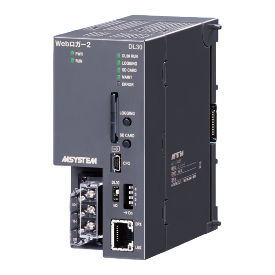
Function Setting DIP SW Terminal Fixing Screw Terminal Block for DL30 RUN Contact Output, Power Supply V (-) Ethernet Indicator LEDs Terminal Cover RJ-45 Connector for Ethernet Specifications BOTTOM VIEW Base Fixing Screw Lock Tab DL30-G USERS MANUAL EM-8571-G Rev.2... - Page 13 ■ CONFIGURATOR SELECT SW SW POSITION CONFIGURATION OBJECT DL30 Configuring the DL30-G using the DL30GCFG or a terminal software program (*) Configuring the R30 series I/O modules using the R30CFG (*) Factory setting ■ DIP SW DL30-G CONFIGURATION USB CONNECTION...
- Page 14 Pressing and holding the button for 4 seconds turns SD CARD LED off to make the card safely removed. ■ TERMINAL ASSIGNMENT FUNCTION RUN contact output RUN contact output U(+) U(+) Power supply (24 V DC) V(-) V(−) Power supply (0 V DC) RUN contact output RUN contact output Not used Functional earth DL30-G USERS MANUAL EM-8571-G Rev.2...
-
Page 15: Installation
2. Installation 2.1 Things to prepare Modules • Web data logger model: DL30-G (hereinafter also referred to as “DL30,” “unit,” or “device”) • R30 series I/O modules • Installation base model: R30BS Other than modules • PC • USB cable (USB (A) male - USB (mini B) male) •... -
Page 16: Preparation Of Configurator Software
2.3 Preparation of configurator software Install the configurator software programs on a PC in order to set up the DL30-G and each I/O module. 2.3.1 Configurator software for DL30-G: DL30GCFG Installing DL30GCFG Download DL30GCFG from the website of M-System, and complete the installation simply by extracting it into any folder. - Page 17 NOTES • If the driver software is not automatically installed, and/or the added COM port is not listed in the options, download the driver from M-System website http://www.m-system.co.jp and install it. • The added COM port No. varies from PC to PC.
-
Page 18: Configurator Software For I/O Modules: R30Cfg
(2) Turn on the power supply to the device. (3) Connect the PC and the device using a USB cable. (4) Start up R30CFG, and select the same COM port selected in DL30GCFG. For details, refer to the R30CFG Users Manual. DL30-G USERS MANUAL EM-8571-G Rev.2... -
Page 19: Explanation About Basic Working And Terms
Internal memory data are recorded in the internal nonvolatile memory of the device. This memory is called 'internal memory'. The time cycles used for acquiring I/O values for logging by the DL30-G; fixed at 1 Sampling rate second. The time cycles used for recording I/O values for logging data and report form data. -
Page 20: Setting
Record setting Logging setting Report form setting ▼ Mail reporting setting ▼ Web server setting ▼ Communication function setting ▼ Scheduling function setting ▼ Other settings Refer to the FAQ on M-System web site. http://www.m-system.co.jp/ ➔ DL30-G USERS MANUAL EM-8571-G Rev.2... -
Page 21: Initial Startup Setting
MAINT Configuration ERROR Connector Configuration Select SW LOGGING DL30 SD CARD DL30 V (-) (2) Connect the DL30-G to the PC on which DL30GCFG is installed using a USB cable, and start up DL- 30GCFG. DL30-G USERS MANUAL EM-8571-G Rev.2... - Page 22 Function Setting DIP SW DL30 V (-) CAUTION If the calendar clock battery backup has been enabled, but the device does not start with the correct time, the battery may be exhausted. Consult M-System in such a case. DL30-G USERS MANUAL EM-8571-G Rev.2...
-
Page 23: Network Setting
Set appropriately to suit the usage environment. ■ Connecting via local network (LAN) This is a method in which one DL30-G device connected to the inhouse LAN is monitored by a terminal lo- cated within the same network. ■ Connecting via Internet (WAN) This is a method in which one DL30-G device connected to a broadband router is remotely monitored via the Internet. -
Page 24: Connecting Via Local Area Network (Lan)
3.3.1 Connecting via local area network (LAN) The table below shows network settings required for the respective server functions of the DL30-G. Consult the network administrator for details about the setting. Server function Network setting for DL30-G Web server FTP server Used to transfer and delete data of DL30-G Set the IP address manually. -
Page 25: Ip Address Setting
Set the parameters by referring to the table on the next page. (6) Click [Upload to device] button to transfer the IP address to the DL30-G (At this point, the IP address is not yet changed). Click [Back] to return to the initial window. - Page 26 • Automatic setting (DHCP) Get IP address and other parameters automatically from the DHCP server. Once DHCP is selected, IP address cannot be changed manually. IP address Specify the IP address of the DL30-G. Subnet mask Specify the Subnet mask. Default gateway Specify the IP address of the default gateway.
-
Page 27: Enabling Configuration Via Network (Remote Access Authorization)
(3) Start up DL30GCFG, and click [DL30GCFG] button to display [Confirm access mode] window. (4) Check that the device is correct, and click [Connect] button. (5) The setting information is loaded from the DL30-G, and the [DL30GCFG via network] window is displayed. Set the parameters by referring to the table below. - Page 28 4. Enter 2. Click 5. Upload to device 6. Click 7. Click (7) If the port address has been changed, turn off and on the power supply to the device to activate the trans- ferred setting. DL30-G USERS MANUAL EM-8571-G Rev.2...
- Page 29 At the time of network connection, a dialog is displayed. Enter the login ID and password set in (5). Set networt address Initial Window Connect 1. Click 2. Select 3. Click New network address to be connected CAUTION General Settings (DL30GCFG, Network) cannot be modified via network. DL30-G USERS MANUAL EM-8571-G Rev.2...
-
Page 30: System Setting
DL30 V (-) (2) Connect the DL30-G to the PC on which DL30GCFG is installed, and start up DL30GCFG. (3) Click [Download from device] button to display [Confirm access mode] window. (4) Check that the device is correct, and click [Connect] button. -
Page 31: Name
Name Specify the name of the DL30-G device using up to 32 characters to be displayed on the Web browser. Name Web Browser View Time zone Set the time zone of your region in Hours: (-12 to 13) and Minutes: (0 to 59) -
Page 32: I/O Module Setting
(2) Connect the PC on which R30CFG is installed with the GL30-G using a USB cable. (3) Refer to the [R30CFG Users Manual] and configure setting such as the I/O range, etc. CAUTION The I/O modules cannot be configured via network. DL30-G USERS MANUAL EM-8571-G Rev.2... -
Page 33: Remote I/O Device Setting
Slave 3 A maximum of 32 remote I/O nodes can be connected to one device. Set different IP addresses which do not overlap with the address of the DL30-G for the remote I/O devices (Slave 0 to Slave 31). ■ Remote I/O nodes which can be connected •... -
Page 34: Slmp Device Connection Setting
Slave 2 A maximum of 32 SLMP devices can be connected to single DL30-G device. Set different IP addresses which do not overlap with the address of the DL30-G for the SLMP device (Slave 0 to Slave 31). ■ SLMP-compatible devices that can be connected to the DL30-G •... -
Page 35: I/O Setting
(5) After the setting information is downloaded from the device, the [Configuration] window is displayed. (6) Click [Input/Output] button to open the [Input/Output] window. Initial Window Con rm access mode Con guration 1. Click 2. Click Input/Output 3. Click DL30-G USERS MANUAL EM-8571-G Rev.2... - Page 36 [123.4567890] is entered, it is rounded off to 3 digits after the decimal point to match the initial value 0.000, and therefore becomes [123.457] (The 4th digit after the decimal point is round- ed off). DL30-G USERS MANUAL EM-8571-G Rev.2...
-
Page 37: I/O Slave Setting
3.6.1 I/O slave setting Modbus/TCP remote I/O and SLMP devices that are used to communicate with the DL30-G must be identified with respective IP addresses and relevant settings. The Pause period and Timeout setting are common to all slave devices. - Page 38 Set Node No. of the remote I/O device. Specify a slave No. with which connection is shared. Connection sharing The DL30-G communicates with the slave through the shared connection. NOTES To register a remote I/O which is connected to the 72EM2-M4 through Modbus-RTU (RS- 485), set the IP address of 72EM2-M4 in the [IP address], and the Modbus-RTU node num- ber in the [Node No.].
-
Page 39: Assigning Slmp Device
MD (digital function register), DO (discrete output), or GDO (grouped digital output). Network No. Set Network No. of the SLMP device. Station No. Set Station No. of the SLMP device Processor No. (HEX) Set processor No. of the SLMP device. DL30-G USERS MANUAL EM-8571-G Rev.2... -
Page 40: Communication Setting
• Modbus/TCP Transaction ID management Unintended messages are skipped by the management of Modbus message IDs. • SLMP Timeout Set the wait time for a response after a query has been sent in SLMP communication. DL30-G USERS MANUAL EM-8571-G Rev.2... -
Page 41: Analog Input (Ai)
3.6.2 Analog input (AI) A maximum of 128 points (AI1 to AI128) of analog inputs can be monitored. Assign the analog inputs from the I/O module, remote I/O, or SLMP device connected to the DL30-G by the following procedure. Assigning I/O module to AI (1) Click [Analog input (AI)] button on the [Input/Output] window to display the [Analog input (AI)] window. - Page 42 Up to 4 analog channels can be assigned per module. Module category Compatible module CH No. Module address CH No. in the module R30US2 2 ch module R30SV2 R30SV4 R30SVF4 R30TS4 R30RS4 4 ch module R30MS4 R30US4 R30CT4E R30GCIE1 R30GECT1 N: Module address DL30-G USERS MANUAL EM-8571-G Rev.2...
-
Page 43: Assigning Remote I/O To Ai
(2) Click [Analog input (AI)] button on the [Input/Output] window to display the [Analog input (AI)] window. (3) Double-click a row of the AI channel to be set to display the [AI setting] window. Input/Output Analog input (AI) AI setting 1. Click 2. Double-click DL30-G USERS MANUAL EM-8571-G Rev.2... - Page 44 Enter the slave No. (0 to 31) set in (1). Modbus/TCP register type Select from [Input Register (3X)] or [Holding Register (4X)]. Modbus/TCP register address Set the register address (1 to 65536) in the above register type. DL30-G USERS MANUAL EM-8571-G Rev.2...
-
Page 45: Assigning Slmp Device To Ai
(2) Click [Analog input (AI)] button on the [Input/Output] window to display the [Analog input (AI)] window. (3) Double-click a row of the AI channel to be set to display the [AI setting] window. Input/Output Analog input (AI) AI setting 1. Click 2. Double-click DL30-G USERS MANUAL EM-8571-G Rev.2... - Page 46 Enter the slave No. (0 to 31) set in (1). SLMP device Choose the device code of the SLMP device to be connected. SLMP device No. Set the device No. of the SLMP device to be connected. DL30-G USERS MANUAL EM-8571-G Rev.2...
-
Page 47: Assigning Control Input To Ai
AI setting 1. Click 2. Double-click (2) Set the [CH setting] as [Control input]. 1. Select NOTES [3.12.3 Modbus/TCP slave] and [8.2.6 Modbus/TCP slave] for information on the Mod- bus/TCP slave function and internal registers. DL30-G USERS MANUAL EM-8571-G Rev.2... -
Page 48: Assigning Time Input To Ai
Analog input (AI) AI setting 1. Click 2. Double-click (2) Set the [CH setting] as [Time], and select the item to be used as the input value from [hour / minutes / seconds]. 1. Select 2. Enter DL30-G USERS MANUAL EM-8571-G Rev.2... -
Page 49: Basic Setting (Ai)
Web browser view. Select from 0 / 1 / 2 / 3. Set the engineering unit for the actual value set in the [Scaling]. Engineering unit Can be set using up to 8 characters. DL30-G USERS MANUAL EM-8571-G Rev.2... - Page 50 The CH name and CH comment which have been set are displayed in the initial window or the trend of the Web window. Web Browser View CH name CH comment DL30-G USERS MANUAL EM-8571-G Rev.2...
-
Page 51: Alarm Zone Setting (Ai)
A maximum of 5 zones can be set, and deadband can also be set between zones. (1) Click [Alarm zone setting] button in the [AI setting] to display the [Alarm zone setting] window. AI setting AI alarm zone setting Click DL30-G USERS MANUAL EM-8571-G Rev.2... - Page 52 When the deadband is not set between zone 1 and zone 2, set the same value for the upper limit value of zone 1 and the lower limit value of zone 2. Set similarly for the other zones as well. Web Browser View Trend view Color Data view Color DL30-G USERS MANUAL EM-8571-G Rev.2...
-
Page 53: Upward/Downward Transition Setting (Ai)
Set the mail template number to be sent when an event occurs. Mail template No. Multiple mail templates can be specified. Create the templates in advance. 3.10.2 Mail template setting ➔ Web Browser View Event No. Message Color DL30-G USERS MANUAL EM-8571-G Rev.2... -
Page 54: Md Alarm Output (Ai)
• When MD is turned ON in the alarm output, the ON output continues as long as the input value is within that zone. • If the alarm output is not used, set it as OFF. DL30-G USERS MANUAL EM-8571-G Rev.2... -
Page 55: Do Alarm Output (Ai)
• When DO is turned ON in the alarm output, the ON output continues as long as the input value is within that zone. • If the alarm output is not used, set it as OFF. DL30-G USERS MANUAL EM-8571-G Rev.2... -
Page 56: Gdo Alarm Output (Ai)
• When GDO is turned ON in the alarm output, the ON output continues as long as the input value is within that zone. • If the alarm output is not used, set it as OFF. DL30-G USERS MANUAL EM-8571-G Rev.2... -
Page 57: Resetting Pi Totalized Value (Ai)
(2) Double-click the PI channel to be operated and set as Disable / Enable, and click [OK]. Reset totalized value (PI) 1. Double-click 2. Select 3. Click 4. Click (3) Click [Back] to return to the [AI alarm zone setting] window. DL30-G USERS MANUAL EM-8571-G Rev.2... -
Page 58: Resetting Ma Function Value (Ai)
(1) Click [Alarm zone setting] button in the [AI setting] to display the [Alarm zone setting] window. Click [Reset function value (MA)] button in a specific zone to display the [Reset function value (MA)]. AI setting AI alarm zone setting Reset function value (MA) 1. Click 2. Click DL30-G USERS MANUAL EM-8571-G Rev.2... - Page 59 The CH setting for which the setting is complete in the [Analog input (AI)] window can also be copied to other CHs and only the required portions can be edited. 3.6.10 Copying CH setting ➔ DL30-G USERS MANUAL EM-8571-G Rev.2...
-
Page 60: Discrete Input (Di)
3.6.3 Discrete input (DI) A maximum of 256 points (DI1 to DI256) of discrete inputs can be monitored. Assign the discrete input from the I/O module, remote I/O, or SLMP device connected to the DL30-G by the following procedure. Assigning I/O module to DI (1) Click [Discrete input (DI)] button in the [Input/Output] window to display the [Discrete input (DI)]. - Page 61 Up to 16 DI channels can be assigned per module. Module type Compatible module CH No. Module address CH No. in the module 16 ch module R30XN16A CH10 CH11 CH12 CH13 CH14 CH15 CH16 N: Module address DL30-G USERS MANUAL EM-8571-G Rev.2...
-
Page 62: Assigning Remote I/O To Di
Enter the slave No. (0 to 31) set in (1). Modbus/TCP register type Select between [Coil (0X)] and [Input (1X)]. Modbus/TCP register address Set the register address in the above register type (1 to 65536). DL30-G USERS MANUAL EM-8571-G Rev.2... -
Page 63: Assigning Slmp Device To Di
Enter the slave No. (0 to 31) set in (1). SLMP device Choose the device code of the SLMP device to be connected. SLMP device No. Set the device No. of the SLMP device to be connected. DL30-G USERS MANUAL EM-8571-G Rev.2... -
Page 64: Assigning Analog Input (Ai) To Di
(2) Set the [CH setting] as [AI], and enter the parameters referring to the table below. 1. Select 2. Enter Parameter Description AI CH No. Choose an AI channel to be used for DI AI BIT Choose a bit position of the AI word. DL30-G USERS MANUAL EM-8571-G Rev.2... -
Page 65: Assigning Control Input To Di
Discrete input (DI) DI setting 1. Click 2. Double-click (2) Set the [CH setting] as [Control input]. Select NOTES [3.12.3 Modbus/TCP slave] and [8.2.6 Modbus/TCP slave] for information on the Mod- bus/TCP slave function and internal registers. DL30-G USERS MANUAL EM-8571-G Rev.2... -
Page 66: Basic Setting (Di)
Set the mail template number to be sent when an event occurs. Mail template No. Multiple mail templates can be specified. Create the templates in advance. 3.10.2 Mail template setting ➔ (3) Click [OK] to temporarily store the setting. Web Browser View Event No. Message Color DL30-G USERS MANUAL EM-8571-G Rev.2... -
Page 67: Resetting Pi Totalized Value (Di)
(2) Double-click the PI channel to be operated and set as Disable / Enable. Reset totalized value (PI) 1. Double-click 2. Select 3. Click 4. Click (3) Click [Back] to return to the [DI setting] window. DL30-G USERS MANUAL EM-8571-G Rev.2... -
Page 68: Resetting Ma Function Value (Di)
The CH setting for which the setting is complete in the [Discrete input (DI)] window can also be copied to other CHs and only the required portions can be edited. 3.6.10 Copying CH setting ➔ DL30-G USERS MANUAL EM-8571-G Rev.2... -
Page 69: Pulse Input (Pi)
A maximum of 128 points (PI1 to PI128) of pulse inputs can be monitored. 32 bit integer data such as energy data can also be assigned to PI. Assign the pulse inputs from the I/O module, remote I/O, or SLMP device connected to the DL30-G by the fol- lowing procedure. - Page 70 The retrieved data is recognized as a signed 32 bit integer, and its value is taken as sampling data. Set the filter function. Select from None / Moving average / Delay buffer. Filter Selectable only for the actual (engineering unit) values. DL30-G USERS MANUAL EM-8571-G Rev.2...
-
Page 71: Assigning Remote I/O To Pi
(2) Click [Pulse input (PI)] button in the [Input/Output] window to display the [Pulse input (PI)]. Double-click a row of the PI channel to be set in this window to display the [PI setting] window. Input/Output Pulse input (PI) PI setting 1. Click 2. Double-click DL30-G USERS MANUAL EM-8571-G Rev.2... - Page 72 Check or uncheck the [Invert] check box depending on the order of high/low regis- ters. Check the box when using the M-System's remote I/O. Set the type of the 32 bit data read from the remote I/O. Select from the following.
-
Page 73: Assigning Slmp Device To Pi
(2) Click [Pulse input (PI)] button in the [Input/Output] window to display the [Pulse input (PI)]. Double-click a row of the PI channel to be set in this window to display the [PI setting] window. Input/Output Pulse input (PI) PI setting 1. Click 2. Double-click DL30-G USERS MANUAL EM-8571-G Rev.2... - Page 74 For details, see the Users Manual for the SLMP device. Settable only for the Accumulation. Select the filter function from None / Moving average / Delay buffer. Filter Selectable only for the actual (engineering unit) values. DL30-G USERS MANUAL EM-8571-G Rev.2...
-
Page 75: Assigning Discrete Input (Di) To Pi
(1) Click [Pulse input (PI)] button in the [Input/Output] window to display the [Pulse input (PI)]. Double-click a row of the PI channel to be set in this window to display the [PI setting] window. Input/Output Pulse input (PI) PI setting 1. Click 2. Double-click DL30-G USERS MANUAL EM-8571-G Rev.2... - Page 76 OFF. Sampling (cycle = on second) Real input signal OFF OFF OFF OFF Sampling data ON ON Measuring mode DOWN * Counted if the previous sampling data is ON and not counted if OFF. DL30-G USERS MANUAL EM-8571-G Rev.2...
-
Page 77: Assigning Control Input To Pi
Pulse input (PI) PI setting 1. Click 2. Double-click (2) Set the [CH setting] as [Control input]. Select NOTES [3.12.3 Modbus/TCP slave] [8.2.6 Modbus/TCP slave] for information on the Mod- bus/TCP slave function and internal registers. DL30-G USERS MANUAL EM-8571-G Rev.2... -
Page 78: Assigning Analog Accumulation To Pi
Set the number of pulse counts corresponding to continuous 100% input status for the time unit. Counter rate (0 to 10000) Choose among Minute / Hour / Day. Time unit The lower limit value for AI sampling data (-2000 to 12000) Low-end cutout DL30-G USERS MANUAL EM-8571-G Rev.2... - Page 79 In order to use analog accumulation, choose “%” as “Data Type” . 1 V at 0%, 5 V at 100%. Choose “Hour” as “Time Unit” for the engineering unit m If “Counter Rate” is set to “30” an accumulated value of 30 is given when AI remains at 100% (5 V) for 1 hour. DL30-G USERS MANUAL EM-8571-G Rev.2...
-
Page 80: Assigning Binary Accumulation To Pi
Make sure that the AI range is set between 0 – 65535 and the pulse count is reset to 0 when a count overflow occurs. Note that the DL30-G resets the pulse count to 0 also when the cur- rent value is smaller than the previous value. -
Page 81: Basic Setting (Pi)
Web browser view. Select from 0 / 1 / 2 / 3. Set the engineering unit corresponding to the actual value set in the [Scaling]. Engineering unit Can be set using up to 8 characters. DL30-G USERS MANUAL EM-8571-G Rev.2... -
Page 82: Alarm Zone Setting (Pi)
Configure alarm zones corresponding to the input values. A maximum of 5 zones can be set, and deadbands can also be set between zones. (1) Click [Alarm zone setting] button in the [PI setting] window to display the [PI Alarm zone setting] window. Click PI alarm zone setting DL30-G USERS MANUAL EM-8571-G Rev.2... - Page 83 When the deadband is not set between zone 1 and zone 2, set the same value for the upper limit value of zone 1 and the lower limit value of zone 2. Set similarly for the other zones as well. Web Browser View Trend view Color Data view Color DL30-G USERS MANUAL EM-8571-G Rev.2...
-
Page 84: Upward/Downward Transition Setting (Pi)
Set the mail template number to be sent when an event occurs. Mail template No. Multiple mail templates can be specified. Create the templates in advance. 3.10.2 Mail template setting ➔ Web Browser View Event No. Message Color DL30-G USERS MANUAL EM-8571-G Rev.2... -
Page 85: Md Alarm Output (Pi)
• When MD is turned ON in the alarm output, the ON output continues as long as the input value is within that zone. • If the alarm output is not used, set it as OFF. DL30-G USERS MANUAL EM-8571-G Rev.2... -
Page 86: Do Alarm Output (Pi)
• When DO is turned ON in the alarm output, the ON output continues as long as the input value is within that zone. • If the alarm output is not used, set it as OFF. DL30-G USERS MANUAL EM-8571-G Rev.2... -
Page 87: Gdo Alarm Output (Pi)
• When GDO is turned ON in the alarm output, the ON output continues as long as the input value is within that zone. • If the alarm output is not used, set it as OFF. DL30-G USERS MANUAL EM-8571-G Rev.2... -
Page 88: Resetting Totalized Value (Pi)
(2) Double-click the PI channel to be operated and set as Disable/Enable. Reset totalized value (PI) 1. Double-click 2. Select 3. Click 4. Click (3) Click [Back] to return to the [PI Alarm zone setting] window. DL30-G USERS MANUAL EM-8571-G Rev.2... -
Page 89: Resetting Ma Function Value (Pi)
(1) Click [Alarm zone setting] button in the [PI setting] window to display the [PI Alarm zone setting] window. Click [Reset function value (MA)] button in a specific zone to display the [Reset function value]. PI setting 1. Click PI alarm zone setting Reset function value (MA) 2. Click DL30-G USERS MANUAL EM-8571-G Rev.2... - Page 90 The CH setting for which the setting is complete in the [Pulse input (PI)] window can also be copied to other CHs and only the required portions can be edited. 3.6.10 Copying CH setting ➔ DL30-G USERS MANUAL EM-8571-G Rev.2...
-
Page 91: Resetting Pi Counts In Regular Intervals
Assign a pulse input channel to be measured. Mode Hour Choose hour and Logging Enable Storing rate time unit offset (Apply same Offset (min.) Logging setting to all hours (00 Offset (sec.) to 23) Assign a pen with PI1. DL30-G USERS MANUAL EM-8571-G Rev.2... - Page 92 Storing rate time unit Logging Offset (sec.) Dateline (hour) Day of week Check all days of the week. Assign a pen with PI1. Refer to [3.8.1 Data logging] for detailed settings of data logging. DL30-G USERS MANUAL EM-8571-G Rev.2...
-
Page 93: Analog Function Register (Ma)
3.6.5 Analog function register (MA) A maximum of 256 points of analog computation functions (MA1 to MA256) can be used. Assign MA channels to the DL30-G following the below procedure. Basic setting (MA) (1) Click [Analog function register (MA)] button in the [Input/Output] window to display the [Analog function register (MA)] window. - Page 94 The held value is output when the unit is restarted. Memory at power loss This parameter is available for MA128 to MA159 only and when the [Function] is disa- bled. [Initial value] invalid when this function is enabled. DL30-G USERS MANUAL EM-8571-G Rev.2...
- Page 95 Values taken within the same sampling cycle are valid when the relevant CH No. > MA CH No. Values taken from the previous sampling cycle are valid when the relevant CH No. ≤ MA CH No. DL30-G USERS MANUAL EM-8571-G Rev.2...
- Page 96 When Z value is <= 0, a value taken from the previous sampling cycle is used. F value calculation Error is recorded in the system log. NOTES Refer to [3.6.4 Pulse input (PI)] > [Assigning analog accumulation to PI] for details of analog accumulation method. DL30-G USERS MANUAL EM-8571-G Rev.2...
-
Page 97: Alarm Zone Setting (Ma)
When the deadband is not set between zone 1 and zone 2, set the same value for the upper limit value of zone 1 and the lower limit value of zone 2. Set similarly for the other zone as well. Web Browser View Trend view Color Data view Color DL30-G USERS MANUAL EM-8571-G Rev.2... -
Page 98: Upward/Downward Transition Setting (Ma)
Set the mail template number to be sent when an event occurs. Mail template No. Multiple mail templates can be specified. Create the templates in advance. 3.10.2 Mail template setting ➔ Web Browser View Event No. Message Color DL30-G USERS MANUAL EM-8571-G Rev.2... -
Page 99: Md Alarm Output (Ma)
• When MD is turned ON in the alarm output, the ON output continues as long as the input value is within that zone. • If the alarm output is not used, set it as OFF. DL30-G USERS MANUAL EM-8571-G Rev.2... -
Page 100: Do Alarm Output (Ma)
• When DO is turned ON in the alarm output, the ON output continues as long as the input value is within that zone. • If the alarm output is not used, set it as OFF. DL30-G USERS MANUAL EM-8571-G Rev.2... -
Page 101: Gdo Alarm Output (Ma)
• When GDO is turned ON in the alarm output, the ON output continues as long as the input value is within that zone. • If the alarm output is not used, set it as OFF. DL30-G USERS MANUAL EM-8571-G Rev.2... -
Page 102: Resetting Totalized Value (Ma)
(2) Double-click the PI channel to be operated and set as Disable/Enable. Reset totalized value (PI) 1. Double-click 2. Select 3. Click 4. Click (3) Click [Back] to return to the [MA alarm zone setting] window. DL30-G USERS MANUAL EM-8571-G Rev.2... -
Page 103: Resetting Function Value (Ma)
(2) Double-click the MA channel to be operated and set as Disable / Enable. Reset function value (MA) 1. Double-click 2. Select 3. Click 4. Click (3) Click [Back] to return to the [MA alarm zone setting] window. DL30-G USERS MANUAL EM-8571-G Rev.2... -
Page 104: Control On Web Browser (Ma)
The CH setting for which the setting is complete in the [Analog function register (MA)] window can also be copied to other CHs and only the required portions can be edited. 3.6.10 Copying CH setting ➔ DL30-G USERS MANUAL EM-8571-G Rev.2... -
Page 105: Digital Function Register (Md)
When a larger No. DI channel is used to generate a result for a smaller No. DI channel, the previous sampling data is used for the computation. Assign MD channels to the DL30-G following the below procedure. Basic setting (MD) (1) Click [Digital function register (MD)] button in the [Input/Output] window to display the [Digital function register (MD)] window. - Page 106 Select a function among: None / Equal / AND / OR / XOR / NOT / RUN. Function RUN: MD turns on when the DL30-G is started up. Set parameters required for the selected function. Consecutive: 3 or more consecutive channels can be used for AND and OR operation.
- Page 107 Mail template No. Multiple mail templates can be specified. Create the templates in advance. 3.10.2 Mail template setting ➔ Web Browser View Trend view Color Data view Color Web Browser View Event No. Message Color DL30-G USERS MANUAL EM-8571-G Rev.2...
- Page 108 OFF delay is disabled When the preset time of Self-reset timer has elapsed, ‘OFF’ is written in [Memory at power loss]. When power loss occurs, the Self-reset timer operates in OFF state when the power is recovered. DL30-G USERS MANUAL EM-8571-G Rev.2...
-
Page 109: Control On Web Browser (Md)
• When the user has logged in the web server using the login ID and password for web browsing, the user is only allowed to control channels selected in the [Channel control func- tion setting]. 3.11.4 Login ID / password / port address setting (web browser access) ➔ DL30-G USERS MANUAL EM-8571-G Rev.2... - Page 110 (valid according to preset time) • E-mail delivery success • Modbus/TCP master, node communication error • Scheduling function • E-mail delivery failure • FTP client, slave communication error • FTP client communication failure • AI/PI/MA zone limit alarm DL30-G USERS MANUAL EM-8571-G Rev.2...
-
Page 111: Resetting Pi Totalized Value (Md)
(2) Double-click PI channel to be operated and set as Disable / Enable. Reset totalized value (PI) 1. Double-click 2. Select 3. Click 4. Click (3) Click [Back] to return to the [MD setting] window. DL30-G USERS MANUAL EM-8571-G Rev.2... -
Page 112: Resetting Ma Function Value (Md)
The CH setting for which the setting is complete in the [Digital function register (MD)] window can also be cop- ied to other CHs and only the required portions can be edited. 3.6.10 Copying CH setting ➔ DL30-G USERS MANUAL EM-8571-G Rev.2... -
Page 113: Which Functions Assigned To Md
Which functions assigned to MD? Functions and zones assigned to the respective MD channels are displayed. Input/Output Digital function register (MD) Which functions assigned to MD? 1. Click 2. Click DL30-G USERS MANUAL EM-8571-G Rev.2... -
Page 114: Analog Output (Ao)
3.6.7 Analog output (AO) A maximum of 64 analog signals (AO1 to AO64) can be output. Assign the analog outputs from the I/O module, remote I/O, or SLMP device connected to the DL30-G by the following procedure. Assigning I/O module to AO (1) Click [Analog output (AO)] button in the [Input/Output] window to display the [Analog output (AO)] window. - Page 115 1. Select Up to 4 AO channels can be assigned per module. Module category Compatible module CH No. Module address CH No. in the module R30SYV4 R30YS4 4 ch module R30GCIE1 R30GECT1 N: Module address DL30-G USERS MANUAL EM-8571-G Rev.2...
-
Page 116: Assigning Remote I/O To Ao
Slave No. Enter the slave No. (0 to 31) set in (1). Modbus/TCP register type Fixed at [Holding Register (4X)]. Modbus/TCP register address Set the register address (1 to 65536) in the above register type. DL30-G USERS MANUAL EM-8571-G Rev.2... -
Page 117: Assigning Slmp Device To Ao
Enter the slave No. (0 to 31) set in (1). SLMP device Choose the device code of the SLMP device to be connected. SLMP device No. Set the device No. of the SLMP device to be connected. DL30-G USERS MANUAL EM-8571-G Rev.2... -
Page 118: Basic Setting (Ao)
Select from 0 / 1 / 2 / 3. Set the engineering unit corresponding for the actual value set in the [Scaling]. Engineering unit Can be set using up to 8 characters. Initial value Specify the initial value set to the AO. DL30-G USERS MANUAL EM-8571-G Rev.2... -
Page 119: Control On Browser (Ao)
• When the user has logged in the web server using the login ID and password for web browsing, the user is only allowed to control channels selected in the [Channel control func- tion setting]. 3.11.4 Login ID / password / port address setting (web browser access) ➔ DL30-G USERS MANUAL EM-8571-G Rev.2... -
Page 120: I/O Mapping (Ao)
3.6.10 Copying CH setting ➔ NOTES Channels assigned for I/O mapping function cannot be controlled on the web browser or used for alarm output. Any setting for the web browser control or the alarm output is invalid. DL30-G USERS MANUAL EM-8571-G Rev.2... -
Page 121: Discrete Output (Do)
3.6.8 Discrete output (DO) A maximum of 128 points of discrete signals (DO1 to DO128) can be output. Assign the discrete outputs from the I/O module, remote I/O, or SLMP device connected to the DL30-G by the following procedure. Assigning I/O module to DO (1) Click [Discrete output (DO)] button in the [Input/Output] window to display the [Discrete output (DO)] win- dow. - Page 122 Up to 16 DO channels can be assigned per module. Module type Compatible module CH No. Module address CH No. in the module R30YN16A 16 ch module R30YN16C CH10 CH11 CH12 CH13 CH14 CH15 CH16 N: Module address DL30-G USERS MANUAL EM-8571-G Rev.2...
-
Page 123: Assigning Remote I/O To Do
Description Slave No. Enter the slave No. (0 to 31) set in (1). Modbus/TCP register type Fixed at [Coil (0X)]. Modbus/TCP register address Set the register address in the above register type (1 to 65536). DL30-G USERS MANUAL EM-8571-G Rev.2... -
Page 124: Assigning Slmp Device To Do
Enter the slave No. (0 to 31) set in (1). SLMP device Choose the device code of the SLMP device to be connected. SLMP device No. Set the device No. of the SLMP device to be connected. DL30-G USERS MANUAL EM-8571-G Rev.2... -
Page 125: Basic Setting (Do)
Display comment Set strings corresponding to ON and OFF, respectively. (ON) Can be set using up to 8 characters. (OFF) Color (ON) Set the colors corresponding to ON and OFF, respectively. (OFF) DL30-G USERS MANUAL EM-8571-G Rev.2... -
Page 126: Control On Browser (Do)
• When the user has logged in the web server using the login ID and password for web browsing, the user is only allowed to control channels selected in the [Channel control func- tion setting]. 3.11.4 Login ID / password / port address setting (web browser access) ➔ DL30-G USERS MANUAL EM-8571-G Rev.2... - Page 127 • Modbus/TCP master, node communication error • Scheduling function • Control by Modbus/TCP slave function • FTP client, slave communication error • E-mail delivery success • AI/PI/MA zone limit alarm • E-mail delivery failure • FTP client communication failure DL30-G USERS MANUAL EM-8571-G Rev.2...
-
Page 128: I/O Mapping (Do)
Channels assigned for I/O mapping function cannot be controlled on the web browser and the scheduling function, or used for alarm output. Any setting for the web browser control, alarm output, or schedule output is invalid. DL30-G USERS MANUAL EM-8571-G Rev.2... -
Page 129: Which Functions Assigned To Do
Which functions assigned to DO? Functions and zones assigned to the respective DO channels are displayed. Input/Output Discrete output (DO) Which functions assigned to DO? 1. Click 2. Click DL30-G USERS MANUAL EM-8571-G Rev.2... -
Page 130: Grouped Digital Output (Gdo)
Digital function (MD) and Discrete output (DO) channels can be grouped and defined as a virtual channel. Operation on a single GDO is effective for all MD and DO channels registered in the GDO. Assign grouped digital outputs to the DL30-G following the procedure given below. Basic setting (GDO) (1) Click [Grouped digital output (GDO)] button in the [Input/Output] window to display the [Grouped digital output (GDO)] window. - Page 131 Set a description for the channel using up to 16 characters with the tag name, etc. Display comment Set strings corresponding to ON and OFF, respectively. (ON) Can be set using up to 8 characters. (OFF) Color (ON) Set the colors corresponding to ON and OFF, respectively. (OFF) DL30-G USERS MANUAL EM-8571-G Rev.2...
-
Page 132: Grouped Channels
3. Click Parameter Description Type Select either 'MD' or 'DO'. Specify the channel No. Assign each CH by following the above procedure. NOTES DO assigned for I/O mapping function cannot be added to the [Grouped channels]. DL30-G USERS MANUAL EM-8571-G Rev.2... -
Page 133: Control On Browser (Gdo)
• When the user has logged in the web server using the login ID and password for web browsing, the user is only allowed to control channels selected in the [Channel control func- tion setting]. 3.11.4 Login ID / password / port address setting (web browser access) ➔ DL30-G USERS MANUAL EM-8571-G Rev.2... - Page 134 • Modbus/TCP master, node communication error • Scheduling function • Control by Modbus/TCP slave function • FTP client, slave communication error • E-mail delivery success • AI/PI/MA zone limit alarm • E-mail delivery failure • FTP client communication failure DL30-G USERS MANUAL EM-8571-G Rev.2...
-
Page 135: I/O Mapping (Gdo)
Any setting for the web browser control, alarm output, or schedule output is invalid. • When the MD or DO in the GDO which is I/O mapped is grouped into another GDO, output of the MD or DO in the I/O mapped-GDO has priority. DL30-G USERS MANUAL EM-8571-G Rev.2... -
Page 136: Which Functions Assigned To Gdo
Which functions assigned to GDO? Functions and zones assigned to the respective GDO channels are displayed. Input/Output Grouped digital output (GDO) Which functions assigned to GDO? 1. Click 2. Click DL30-G USERS MANUAL EM-8571-G Rev.2... -
Page 137: Copying Ch Setting
CHs and only the required portions can be edited. 1. Right-click on the row to be copied Click on [Copy] 2. Right-click on the destination row Click on [Paste] 3. The contents are copied 4. Edit only the required portion DL30-G USERS MANUAL EM-8571-G Rev.2... -
Page 138: Applying Setting
3.6.11 Applying setting To transfer the temporarily stored setting values to the DL30-G, click [Back] from the [Input/Output] window to return to the [Configuration], and then click [Upload to device] button. Input/Output Con guration Con rm uploading 1. Click Con rm access mode 2. -
Page 139: I/O Mapping Setting
• Values applied for I/O mapping: % (AI): Input values are applied as they are to the output. Int, Uint (AI): Engineering unit values are applied to the output. DI, MD: Current state is applied to the output. DL30-G USERS MANUAL EM-8571-G Rev.2... -
Page 140: Logging Function Setting
DL30 V (-) (2) Connect the DL30-G to a PC in which DL30GCFG is installed, and start up DL30GCFG. (3) Click [Download from device] button in the initial window to display [Confirm access mode] window. (4) Check that the device is correct, and click [Connect] button. -
Page 141: Data Logging
The first data row advances (no blank row) if one or more Headers are not defined. If all Headers are blank, the first set of Date and time and CH data starts at the row 1. DL30-G USERS MANUAL EM-8571-G Rev.2... -
Page 142: Logging Setting
Uncheck the days of the week when logging is not required. For example, uncheck [Sun] to cancel the logging on Sundays. SD card record character set Choose the character set for the data stored in the SD card between S-JIS and UTF-8. DL30-G USERS MANUAL EM-8571-G Rev.2... - Page 143 Specify the lower limit of the data. • Mode A pre-defined value can be applied in the Report form when the DL30-G is unable to acquire data or when the data is out of the specified range. Choose among: Previous value / Fixed value / Fixed characters.
- Page 144 [Error mode] is applied only all data sampled within the time interval specified as [Storing rate] are in error. The DL30-G performs the operation specified for the [Sampling method] if one or more data samples are acquired within the cycle.
-
Page 145: Starting Logging Automatically
If [SD card auto delete] is set as [Disable], data cannot be transferred to the SD card from the internal memory once there is no more space on the SD card. Data continues to be recorded in the memory blocks, but after the last memory block, the first memory block is overwritten. DL30-G USERS MANUAL EM-8571-G Rev.2... -
Page 146: Event Log
■ Communication log Column Row 1 Date and time Protocol Result Form No. / File name Transmission times Message Row 2 (data) (data) (data) (data) (data) (data) Column 4, 5, and 6 are blank for SNTP error. DL30-G USERS MANUAL EM-8571-G Rev.2... - Page 147 Row 5 Schedule unit Schedule Pattern Operation (Permanent Reg. No. Date Pattern No. unit name name ID (* schedule) *1. CFG1 to 8: DL30GCFG authentication ID, WEB1 to 32: Web authentication ID, USB: USB connection DL30-G USERS MANUAL EM-8571-G Rev.2...
-
Page 148: Event Log Setting
Choose the character set for the data stored in the SD card between S-JIS and UTF-8. System log setting (1) Display the [Event] window following the same procedure as for the Event log. (2) Set [System log] as [Enable], otherwise no data is recorded. Select Enable DL30-G USERS MANUAL EM-8571-G Rev.2... -
Page 149: Communication Log Setting
Set [SD card auto delete] as [Enable] to automatically delete the data. Select Enable For more explanations on the target files and the timing of deletion, refer to [8.2.4 SD card] > [Automatic file deleting function]. DL30-G USERS MANUAL EM-8571-G Rev.2... -
Page 150: Report Form Setting
Row 36 CH1 total CH2 total CH128 total Row 37 Average CH1 average CH2 average CH128 average Row 38 Maximum CH1 max. CH2 max. CH128 max. Row 39 Minimum CH1 min. CH2 min. CH128 min. DL30-G USERS MANUAL EM-8571-G Rev.2... -
Page 151: Yearly Report
CSV file of the day does not include these rows yet. However, the final four rows always show on the Web browser view. Web Browser View 8 channels DL30-G USERS MANUAL EM-8571-G Rev.2... -
Page 152: Report Form Setting
(4) Check that the device is correct, and click [Connect] button. (5) Once the setting information has been loaded from the device, the [Configuration] is displayed. Initial Window Con rm access mode Con guration 1. Click 2. Click DL30-G USERS MANUAL EM-8571-G Rev.2... - Page 153 SD card record character set Choose the character set for the data stored in the SD card between S-JIS and UTF-8. Page title Specify a page title for each of Daily, Monthly, and Yearly report (max. 32 characters) DL30-G USERS MANUAL EM-8571-G Rev.2...
-
Page 154: Report Form Contents Setting
Specify the lower limit of the data. • Mode A pre-defined value can be applied in the Report form when the DL30-G is unable to acquire data or when the data is out of the specified range. Choose among: Previous value / Fixed value / Fixed characters. - Page 155 [Error mode] in Daily reports is applied only all data sampled within one hour are in error. The DL30-G performs the operation specified for the [Sampling method] if one or more data samples are acquired within the hour.
- Page 156 • In order to report in the Daily reports the difference per hour for a PI channel, specify an AI channel with [Time] input so that the data is reset every hour. Choose [Momentary value] for the sampling method. DL30-G USERS MANUAL EM-8571-G Rev.2...
-
Page 157: E-Mailing Report Forms
• E-mails are not sent if the specified e-mail template does not contain a report form as at- tachment. • Report form files are generated in the SD card. No file is saved if an SD card is not inserted in the slot. DL30-G USERS MANUAL EM-8571-G Rev.2... -
Page 158: Automatically Deleting Report Forms In Sd Card
Set the date to start monthly report. Date to start Monthly report Setting range: 1 to 28 (date) Set the month to start yearly report. Month to start Yearly report Setting range: 1 to 12 (month) DL30-G USERS MANUAL EM-8571-G Rev.2... -
Page 159: Mail Reporting Setting
3.10 Mail reporting setting The DL30-G is equipped with the Mail reporting function for sending emails. NOTES The DL30-G cannot receive an e-mail. (1) Turn [Configuration Select SW] to the [DL30] side. DL30 RUN LOGGING SD CARD MAINT Configuration ERROR... -
Page 160: Mail Server Setting
3.10.1 Mail server setting (1) Click [Communication] button in the [Configuration] window. Click [SMTP/POP3] button to display the [SMTP/POP3] window. Con guration 1. Click Communication SMTP/POP3 3. Enter 2. Click DL30-G USERS MANUAL EM-8571-G Rev.2... - Page 161 POP3 server IP address Set the domain name or IP address of the POP3 server. No entry (Blank) Set the DL30-G mail account name. DL30-G e-mail account No entry (Blank) Set it as the string before @ in the mail address.
- Page 162 • POP3 is incorporated for POP before SMTP authentication. DL30-G cannot receive e-mails. • SMTP over SSL authentication of the DL30-G is intended only for encryption. Therefore the certification issued by the mail server is not verified. • Many mail servers are equipped with antispam tactic.
-
Page 163: Mail Template Setting
(3) Double-click a row in the list and register the Name and Address (e-mail address). Up to 64 e-mail recipients can be registered. Con guration E-mail Address list 1. Click 2. Click 4. Enter 3. Double-click DL30-G USERS MANUAL EM-8571-G Rev.2... -
Page 164: Creating Mail Templates
• When the [Mode] is disabled, the relevant event and regular report settings are also changed accordingly. For temporarily disabling a particular mailing function while maintaining the setting itself, set [Enabled time period] as [Pause]. • When the [Mode] is disabled, the test mailing function is also disabled. DL30-G USERS MANUAL EM-8571-G Rev.2... - Page 165 Choose [Non-business hours] for applying the filter to “the out of business hours in a non- business days. (5) Click [Address list] to display the [Address list]. Double-click a row of the recipient name and choose [To]. Mail template setting 1. Click 2. Double-click Address list 3. Enter DL30-G USERS MANUAL EM-8571-G Rev.2...
- Page 166 (7) An alarm output can be turned ON/OFF when the mail reporting is successful. 3. Enter Parameter Description Mode Choose among: None / ON / OFF. Type Choose an output type among: MD / DO / GDO. Choose a channel No. DL30-G USERS MANUAL EM-8571-G Rev.2...
-
Page 167: Original Html Tag
Event message (valid only for an event report) NOTES The original tags for an event report is not converted but appear as they are in a mail body text if such tags are used for other than an event report. DL30-G USERS MANUAL EM-8571-G Rev.2... -
Page 168: Regular Reporting
Double-click one or more [Hour] rows and set [Send] as [Enable]. Specify time offsets (minutes and seconds). To report on the hour, set both values to 0. Regular report 2. Double-click Set time to send 1. Click 3. Enter DL30-G USERS MANUAL EM-8571-G Rev.2... -
Page 169: Report Failure Output
Choose an output type among: MD / DO / GDO. Choose a channel No. (4) Once the setting is complete, click [OK] and [Back] to temporarily store the setting. To activate the setting, return to the [Configuration] and click [Upload to device] button. DL30-G USERS MANUAL EM-8571-G Rev.2... -
Page 170: E-Mailing Calendar
(3) Check days of the week for common Holidays and Non-business days applicable to all weeks. 1. Select 2. Click [Holiday] cells are indicated in red color. [Holiday + Non-business day] cells are in light green. [Weekday (except the Holidays) + Non-business day] cells are in light blue. DL30-G USERS MANUAL EM-8571-G Rev.2... - Page 171 (5) Specify the regular business hours for up to 6 patterns. Set the start and the end hours for each pattern. Enter (6) Once the setting is complete, click [OK] to temporarily store the setting. DL30-G USERS MANUAL EM-8571-G Rev.2...
-
Page 172: Test Mail
3.10.6 Test mail Event reporting and regular mailing can be tested on the DL30GCFG. 6.1.2 Maintenance menu (DL30GCFG) > Test mail ➔ DL30-G USERS MANUAL EM-8571-G Rev.2... -
Page 173: Web Server Setting
(4) Check that the device is correct, and click [Connect] button. (5) Once the setting information has been loaded from the device, the [Configuration] is displayed. Initial Window Con rm access mode Con guration 1. Click 2. Click DL30-G USERS MANUAL EM-8571-G Rev.2... -
Page 174: Top Screen Header Name And Image Setting
Name IMAGE 1 IMAGE 2 IMAGE 3 Name The DL30-G system name can be specified and indicated at the header of the web page. Set Name by referring to [3.4 System setting]. Images 1, 2, and 3 User’s own image files can be placed on the top screen. -
Page 175: Trend Graph Setting
Set the pen assignment, color, and other setting for the trend displayed on the web page. The DL30-G can display a maximum of 64 pens on a total of 16 pages. Pens 1 to 4, Pens 5 to 8, ... are assigned to Page 1, Page 2,..., respectively. - Page 176 Web Browser View Color Thick line Normal line (4) Once the setting is complete, click [OK] to temporarily store the setting. (5) To activate the setting, return to the [Configuration] and click [Upload to device] button. DL30-G USERS MANUAL EM-8571-G Rev.2...
-
Page 177: Page Setting
(0 - 23) Web Browser View Page name (4) Once the setting is complete, click [OK] to temporarily store the setting. (5) To activate the setting, return to the [Configuration] and click [Upload to device] button. DL30-G USERS MANUAL EM-8571-G Rev.2... -
Page 178: Data Display Setting
Data view setting 1. Click 2. Click (2) Check the channels to show on the Data view. Web Browser View NOTES Right-click on the CH list in the [Data view setting] window to check/ uncheck all CH. DL30-G USERS MANUAL EM-8571-G Rev.2... -
Page 179: Login Id / Password / Port Address Setting (Web Browser Access)
NOTES • To use HTTPS protocol, it is required to install a web server certificate on the DL30-G and a local certificate authority on a terminal such as a PC which connects to the DL30-G. - Page 180 (3) Click [CH] in the ID dialog to display the [Channel control function setting] window. Select channel(s) to allow the ID to control. Click [OK] to return to the ID dialog. Web server Channel control function setting 1. Double-click 2. Enter ID dialog 3. Click 2. Click DL30-G USERS MANUAL EM-8571-G Rev.2...
- Page 181 • After changing the login ID and password, use the Update button of the browser to update the cache. • Be sure to change the default ID and password. • It is highly recommended to change the password regularly. DL30-G USERS MANUAL EM-8571-G Rev.2...
-
Page 182: Communication Function Setting
3.12 Communication function setting The DL30-G supports various communication functions including the remote operation of the DL30-G, data downloading from the SD card, and time correction using the SNTP server. (1) Turn [Configuration Select SW] to the [DL30] side. DL30 RUN... -
Page 183: Ftp Server
/ applications supported by the FTP server function, points to note, etc. • Be sure to change the default ID and password. • It is highly recommended to change the password regularly. DL30-G USERS MANUAL EM-8571-G Rev.2... -
Page 184: Ftp Client
If it is left blank, files are transferred to the root directory. NOTES • To use FTPS protocol, external connection must be permitted for port numbers 45967 to 45970. • FTPS is used in explicit mode. DL30-G USERS MANUAL EM-8571-G Rev.2... -
Page 185: Ftp Data Setting
Set as [Enable] to send out a file at the timing of saving. FTP file transfer can be initiated by a command of specific MD (rising edge). Send command Choose either [None] or [MD]. Specify CH used as Send command. DL30-G USERS MANUAL EM-8571-G Rev.2... - Page 186 Set '10' for both the upper limit of Zone 1 and the lower limit of Zone 2. Specify an MD channel to [Alarm output (MD)] for Zone 1. The AI transits from Zone 1 to Zone 2 at 0 minute and the MD output turns on. DL30-G USERS MANUAL EM-8571-G Rev.2...
-
Page 187: Communication Failure Output
Choose an output type among: None / MD / DO / GDO. Choose a channel No. Once the setting is complete, click [OK] to temporarily store the setting. To activate the setting, return to the [Configuration] and click [Upload to device] button. DL30-G USERS MANUAL EM-8571-G Rev.2... -
Page 188: Modbus/Tcp Slave
3.12.3 Modbus/TCP slave The DL30-G supports the Modbus/TCP slave function which allows an external Modbus master device to monitor the DL30-G I/O signals and to perform other operations. (1) Click [Communication] button in the [Configuration] to display the [Communication] window. -
Page 189: Sntp (Automatic Time Correction)
The DL30-G supports the SNTP client function which is used to automatically correct the time clock in the DL30-G. Automatic time correction is executed when the power supply to the DL30-G is turned on, and at 00:00, 06:00, 12:00, and 18:00 hours. -
Page 190: Scheduling Function Setting
3.13 Scheduling function setting The DL30-G is equipped with the scheduling function for manipulating channels of discrete output (DO), digital function register (MD), and grouped digital output (GDO) according to the preset schedule. (1) Turn [Configuration Select SW] to the [DL30] side. -
Page 191: Pattern Setting
(3) Double-click the schedule No. to set in the [Pattern] window to display the [Schedule output setting] win- dow. Scheduler Pattern setting Pattern Pattern name can be edited 1. Click Schedule output setting 2. Double-click 3. Double-click DL30-G USERS MANUAL EM-8571-G Rev.2... - Page 192 Select the channel number. Set the time to start ON operation. Start at The selected channel turns ON from the set start time until the end time. End at Set the time to end the ON operation. DL30-G USERS MANUAL EM-8571-G Rev.2...
-
Page 193: Schedule Unit Setting
Set the end time of the first pattern at 24:00 and set the start time of the second pattern at 0:00. For example, to schedule an output from 21:00 on Sunday to 3:00 on Monday, create two patterns named Pattern1 and Pattern2 as shown below and assign them to Sunday and Monday, respectively. DL30-G USERS MANUAL EM-8571-G Rev.2... -
Page 194: Maintenance Sw Setting
Set the parameters by referring to the table below. Parameter Description Type Select the signal type from: None / DI / MD. Select the channel number. (3) Click [OK] to store the setting and return to the [Scheduler]. DL30-G USERS MANUAL EM-8571-G Rev.2... -
Page 195: Process Operation Monitor Function Setting
3.14 Process operation monitor function setting The DL30-G is equipeed with the process operation monitor function, which allows to monitor process op- eration of channels selected from among Analog input (AI), Pulse input (PI), Analog function register (MA), Discrete input (DI), and Digital function register (MD). -
Page 196: Process Operation Monitor Setting
(3) Edit parameters in the [Process setting] window as needed. 3.14.2 Setting analog data to process ➔ 3.14.3 Setting digital data to process ➔ Con guration Process operation monitor Process setting 1. Click 2. Double-click DL30-G USERS MANUAL EM-8571-G Rev.2... -
Page 197: Setting Analog Data To Process
Digital display (sub1) CH Select the channel to display data value. (5) The status of data set for Channel 1 is recorded every minute (00 seconds of DL30-G clock data) for 48 hours and represents the data in a Gantt chart. ➔... - Page 198 • Gantt chart will be cleared when the type, channel, display comment, or engineering unit of Channel 1 has been changed. • Gantt chart can also be cleared on DL30GCFG. 6.1.2 Maintenance menu (DL30GCFG) > Initializing internal memory ➔ DL30-G USERS MANUAL EM-8571-G Rev.2...
-
Page 199: Setting Digital Data To Process
(3) Select the signal type and channel to display data value for each of 'Digital display (main)' and 'Digital display (sub1)' to 'Digital display (sub3)'. Con guration Process operation monitor Process setting 1. Click 3. Enter 2. Double-click 4. Enter DL30-G USERS MANUAL EM-8571-G Rev.2... - Page 200 Digital display (sub1) CH Select the channel to display data value. (5) The status of data set for Channel 1 is recorded every minute (00 seconds of DL30-G clock data) for 48 hours and represents the data in a Gantt chart. ➔...
-
Page 201: Other Settings
3.15 Other settings 3.15.1 Skipping access mode confirmation in DL30GCFG The dialog box to prompt the user to confirm the access mode when connecting to the DL30-G can be sup- pressed by setting as follows: (1) Start up DL30GCFG. (2) Uncheck the box next to the option [Confirm access mode when connecting.] in the initial window. -
Page 202: Status Monitoring
The status of data uploading by FTP can be confirmed during the setting procedure via DL30GCFG or the terminal software program. Status monitoring via DL30GCFG (1) Connect the DL30-G to a PC with an USB cable. (2) Turn ON the function setting DIP SW1. DL30 RUN... -
Page 203: Status Monitoring Via Terminal Software Program
Status monitoring via Terminal software program (1) Connect the DL30-G to a PC with an USB cable. (2) Turn ON the function setting DIP SW1. DL30 RUN LOGGING SD CARD MAINT ERROR LOGGING SD CARD Function Setting DIP SW DL30... -
Page 204: How To Use The Web Server
4. How to use the Web server Enter the domain name or IP address in the URL entry field of the browser to open the top page of the DL30-G web server. Descriptions in this section are based on the operations on a PC. -
Page 205: Common Menu Bar
4.1 Common menu bar A common menu bar is displayed in all web pages generated by the DL30-G. Screen lock indicator Error indicator Name Menu bar Current date Current time SD card indicator Menu button Menu button Click Menu button to display the menu dialog. -
Page 206: Data Display
When the user intends to access the device with DL30GCFG via network using the login ID and password for remote access, be sure to set the login ID and password for web browsing as well. 3.11.4 Login ID / password / port address setting (web browser access) ➔ DL30-G USERS MANUAL EM-8571-G Rev.2... -
Page 207: Changing Screen Refresh Rate
(3) Enter the auto refresh rate and click [OK]. The refresh rate of the data display pages is changed. NOTES The I/O channels appearing on the Data display are specified in the DL30GCFG. 3.11.3 Data display setting ➔ DL30-G USERS MANUAL EM-8571-G Rev.2... -
Page 208: Trend Graph
Time index showing Page name the rightmost point of the chart Menu bar Page selector Trend area Digital display Graph range Scale Page name The preset page name is displayed. ➔ 3.11.2 Trend graph setting DL30-G USERS MANUAL EM-8571-G Rev.2... -
Page 209: Digital Display
Shown in the color of the current alarm zone when alarm zones are set. Shown in the pen color when no zone is set. Status Shown as a bargraph for AI when the data type is %. Shown as designated. Engineering unit Blank DL30-G USERS MANUAL EM-8571-G Rev.2... -
Page 210: Trend Graph Operation
(change the min. value) NOTES • The modified scale values are valid only while the [Trend] view is displayed. • The modifications can be cleared by [Reset calibration] command. 4.3.2 Trend graph operation > Resetting local calibration ➔ DL30-G USERS MANUAL EM-8571-G Rev.2... -
Page 211: Hiding Pens
(3) To show the hidden graph, click [Pen color] once again. Click Trend graph is hidden NOTES • The modified status (shown/hidden) is valid until the trend data is cleared. • The status (shown/hidden) cannot be switched while the screen is locked. DL30-G USERS MANUAL EM-8571-G Rev.2... -
Page 212: Expanding/Compressing Time Axis
• In case of a touch panel such as an iPad, it is possible to Pinch in to compress, and Pinch out to expand. Pinching-in/-out with a pen being selected expands/shrinks the browser window size. CAUTION Values applied by [Reset calibration] are not cleared by expanding/compressing the time axis. DL30-G USERS MANUAL EM-8571-G Rev.2... -
Page 213: Comparing Graphs (Shifting Graph Along Scale)
• In case of a touch panel such as an iPad, swipe over the trend graph area in the desired direction. • The modifications can be cleared by [Reset calibration] command. 4.3.2 Trend graph operation > Resetting local calibration ➔ DL30-G USERS MANUAL EM-8571-G Rev.2... -
Page 214: Comparing Graphs (Expanding/Contracting Scale)
• In case of a touch panel such as an iPad, pinch in or pinch out over the trend graph area. • The modifications can be cleared by [Reset calibration] command. 4.3.2 Trend graph operation > Resetting local calibration ➔ DL30-G USERS MANUAL EM-8571-G Rev.2... -
Page 215: Changing Screen Refresh Rate
(1) Click the [Menu button (2) Click [Reset calibration ] in the sub-menu. (3) The calibration confirmation dialog will appear. Click [OK]. (4) Local calibration values are reset and the trend graphs return to their initial state. DL30-G USERS MANUAL EM-8571-G Rev.2... -
Page 216: Event Summary
4.4.1 Event summary page contents Up to 2000 events stored in the internal memory are displayed. Page selector Display range selector Event No. lter NOTES The log type which was previously selected is displayed when Cookie is enabled. DL30-G USERS MANUAL EM-8571-G Rev.2... -
Page 217: Event Summary Operation
The screen is not updated when the value is set to 0. (1) Click [Menu button (2) Click [Screen refresh rate ] in the sub-menu. (3) Enter the auto refresh rate and click [OK]. The refresh rate of the event summary pages is changed. DL30-G USERS MANUAL EM-8571-G Rev.2... -
Page 218: Event No. Filter
Event log data can be filtered by Event No. (1) Click [Select ] button to display the [Event No. setting] dialog. (2) Select Event No. and click [OK]. 1. Click 2. Select Event No. 3. Click DL30-G USERS MANUAL EM-8571-G Rev.2... -
Page 219: Report Form
4.5 Report form Click [Menu button ] and select [Report ] to switch to the report form view. 4.5.1 Report form page contents Report form data files stored in the internal memory are listed. Page selector DL30-G USERS MANUAL EM-8571-G Rev.2... -
Page 220: Report Form Operation
“X” at the beginning of the data name. • If the time index of sampling data is no longer continuous due to time adjustment, a new file is created and named with “X” at the beginning of the data name. DL30-G USERS MANUAL EM-8571-G Rev.2... -
Page 221: Data File Download
Folders are listed in the left half of the window, and files are listed in the right half of the window. Page selector Current folder List of folders List of les NOTES Refer to [8.2.5 Data file configurations] for more information about file names and folder struc- tures. DL30-G USERS MANUAL EM-8571-G Rev.2... -
Page 222: Download Operation
If you click a blank space in a file name row, the target file is selected but not downloaded. Deleting files Data can be deleted from the [Maintenance] menu. Data in the internal memory cannot be deleted. 6.2.2 Maintenance menu (Web) > Downloading/deleting SD card files ➔ DL30-G USERS MANUAL EM-8571-G Rev.2... -
Page 223: Schedule
• Channels to operate and start/end time can be changed from the web maintenance menu ( ➔ 4.9.4 Pattern setting) or DL30GCFG (➔ 3.13 Scheduling function setting). • For details of specifications of the scheduling function, see [8.2.11 Schedule]. DL30-G USERS MANUAL EM-8571-G Rev.2... -
Page 224: Selecting Units
4.7.2 Selecting units ] on the [Schedule] menu, and select [Select unit ] to display the [Select unit] dialog. Select the unit to operate, and click [OK]. 1. Select 2. Click DL30-G USERS MANUAL EM-8571-G Rev.2... -
Page 225: One-Time Schedule
• The user cannot use the one-time schedule function if the corresponding schedule unit is not selected in the [Schedule unit control function setting] window for the ID currently logged in the web server. 3.11.4 Login ID / password / port address setting (web browser access) ➔ DL30-G USERS MANUAL EM-8571-G Rev.2... -
Page 226: Permanent Schedule
• The user cannot use the permanent schedule function if the corresponding schedule unit is not selected in the [Schedule unit control function setting] window for the ID currently logged in the web server. ➔ 3.11.4 Login ID / password / port address setting (web browser access) DL30-G USERS MANUAL EM-8571-G Rev.2... -
Page 227: Output Type Maintenance
3.3.4 Enabling configuration via network (remote access authorization) ➔ • Even when the output type is set to OFF, the channel is turned ON when the control output or alarm output of the corresponding channel is set to ON. DL30-G USERS MANUAL EM-8571-G Rev.2... -
Page 228: Process Operation Monitor
Data for 12 hours are displayed per page and data for 48 hours are available to be displayed by scrolling. Time is divided into 6-hour periods Status of the scrolled from 00:00:00. Scrolled point of time point of time. Scrolled point (Right end of Gantt chart) Data for 12 hours DL30-G USERS MANUAL EM-8571-G Rev.2... - Page 229 Blank NOTES • Process operation data is sampled every minute when the clock data of the DL30-G is 00 seconds while the Gantt chart screen is refreshed every 10 seconds. Thus, timing of update of the process operation data may be shifted from the current time shown at the menu bar of the DL30-G web page.
-
Page 230: Andon Screen
The status is updated every second. 3.14.1 Process operation monitor setting ➔ A maximum of 16 processes are displayed per page, and sections with no processes assigned will be blank. Last refreshed time of the Andon screen DL30-G USERS MANUAL EM-8571-G Rev.2... -
Page 231: Operations
Click the Screen lock indicator to lock the screen such that the screen will not be refreshed. Click Gantt chart history Click Click the [<] or [>] button to scroll the Gantt chart history by 1 minute. DL30-G USERS MANUAL EM-8571-G Rev.2... -
Page 232: Setting Change On Browser
[Suppress additional dialog display], but DO NOT select these options. If it is selected, subsequent dialogs are not displayed, and this also prevents the operation which requires display of the confirmation dialog. 8.1.10 Web server ➔ DL30-G USERS MANUAL EM-8571-G Rev.2... -
Page 233: E-Mail Setting
(5) Click [OK] when a message dialog “Are you sure to save the list?” appears on the window. (6) After the setting has been successfully applied, a message dialog [Completed] appears. Click [OK] to return to the [E-mail setting] window. DL30-G USERS MANUAL EM-8571-G Rev.2... -
Page 234: Mail Template Setting
(2) Click [Report Form setting] (= Mail template setting in DL30GCFG) button to display the [Report Form Set- ting] window. (3) Click [Edit] button to the right of the template to be modified. 2. Click 1. Click 3. Click DL30-G USERS MANUAL EM-8571-G Rev.2... -
Page 235: Test Mail
• When the [Mode] is disabled, the test mailing function is also disabled. Test mail A test mail can be sent from the [Report Form setting] window. Click [Test mail] button of the mail template for testing. 6.2.2 Maintenance menu (Web) > Test mail ➔ DL30-G USERS MANUAL EM-8571-G Rev.2... -
Page 236: Trend
(1) Click [Trend Setting] button in the [Maintenance] menu to display the [Select Trend Page] window. (2) Click [Edit] button to the right of the page to be modified to display the [Trend Page setting] window. (3) Enter the [Page name] and other settings. 2. Click 1. Click 3. Enter DL30-G USERS MANUAL EM-8571-G Rev.2... - Page 237 Click [OK]. 2. Click 1. Click 3. Click (7) After the setting has been successfully applied, a message dialog [Completed] appears. Click [OK]. (8) Click [CANCEL] button to return to the [Trend page setting] window. DL30-G USERS MANUAL EM-8571-G Rev.2...
-
Page 238: Alarm Zone Setting
(2) Switch the signal type, if necessary, by clicking the signal type button at the top left of the window. Choose a channel. (3) The [Zone Setting] window is displayed. 1. Click 2. Click DL30-G USERS MANUAL EM-8571-G Rev.2... - Page 239 Click [OK]. 1. Click 2. Click 3. Click (6) After the setting has been successfully applied, a message dialog [Completed] appears. Click [OK]. CAUTION Zone names cannot be changed on the web browser. Use the DL30GCFG. DL30-G USERS MANUAL EM-8571-G Rev.2...
-
Page 240: Pattern Setting
4.7 Schedule (1) Click [Pattern Setting] button in the [Maintenance] menu to display the [Pattern List]. (2) Click [Edit] button of the pattern to change to display the [Pattern] screen. 2. Click 1. Click 4. Click DL30-G USERS MANUAL EM-8571-G Rev.2... - Page 241 Select each parameter and click [OK]. (4) Click [OK] on the [Pattern] screen to apply the change. 1. Click 2. Select 3. Click 4. Click NOTES • For details of the specifications of the scheduling function, see [8.2.11 Schedule]. DL30-G USERS MANUAL EM-8571-G Rev.2...
-
Page 242: Maintenance
4.10 Maintenance Click the [Menu button ] and select [Maintenance ] to display the [Maintenance] menu. For details, see [6.2 Maintenance on Web browser]. DL30-G USERS MANUAL EM-8571-G Rev.2... -
Page 243: User Defined Web Browser View
User is allowed to freely create Web screens Using HTML or JavaScript. Access [http://<DL30G-IP address>/user/<content file name>] from the browser to show the user defined win- dows. [7. User defined browser view] for detailed information. DL30-G USERS MANUAL EM-8571-G Rev.2... -
Page 244: Unit Operation
The SD card lamp remains ON as long as the SD card is being recognized, and blinks while the SD card is being accessed. SD CARD LED ON DL30 RUN LOGGING SD CARD MAINT SD CARD ERROR LOGGING SD CARD DL30 ① ④ ② ⑤ ③ V(-) ⑥ DL30-G USERS MANUAL EM-8571-G Rev.2... -
Page 245: Data Logging
The LOGGING lamp is always ON while logging is in progress. LOGGING, SD CARD LED ON DL30 RUN LOGGING SD CARD LOGGING MAINT ERROR LOGGING SD CARD SD CARD DL30 ① ④ ② ⑤ ③ V(-) ⑥ DL30-G USERS MANUAL EM-8571-G Rev.2... -
Page 246: Function Setting Dip Switch
Logging is stopped, e-mail reporting, FTP client file transfer, and schedule outputs are disabled. DL30 RUN LOGGING SD CARD MAINT ERROR LOGGING SD CARD Function Setting DIP SW DL30 V (-) 5.4 Stopping the unit Stop logging, remove the SD card, and then turn off the power supply. DL30-G USERS MANUAL EM-8571-G Rev.2... -
Page 247: Maintenance
1. Click NOTES The setting file which is stored in the root folder of the SD card can be retrieved from the Web browser. To do so, specify the file name using single byte alphanumeric characters. DL30-G USERS MANUAL EM-8571-G Rev.2... -
Page 248: Reading Setting File
The setting information stored in the file can be retrieved using DL30GCFG. (1) Click [Read file] button in the DL30GCFG initial window. (2) Select the file and click [Open] to retrieve the setting values. Initial Window 2. Click 1. Click 3. Click DL30-G USERS MANUAL EM-8571-G Rev.2... -
Page 249: Maintenance Menu (Dl30Gcfg)
6.1.2 Maintenance menu (DL30GCFG) Maintenance of the DL30-G can be performed from the [Maintenance] window. (1) Connect the device to a PC in which DL30GCFG is installed, and start up DL30GCFG. (2) Click [Maintenance] button in the initial window to display [Confirm access mode] window. -
Page 250: Time Correction
Time correction The calendar clock in the DL30-G can be manually adjusted. Click [Date/Time] button in the [Maintenance] window to open the [Date/Time] dialog. The current system time of the PC is initially displayed. Enter the time to be set and click [Apply] button to reflect the set time in the internal RTC (Real Time Clock) of the device. -
Page 251: Starting/Stopping Data Logging
Click [Start/stop logging] button in the [Maintenance] window to open the [Start/stop logging] dialog. Click [Start/stop logging] button and a dialog for confirmation appears. Click [OK] to start the logging operation or stops the logging operation in progress. Maintenance 2. Click 1. Click 3. Click DL30-G USERS MANUAL EM-8571-G Rev.2... -
Page 252: One-Time Schedule Assignment
(4) Select the pattern to which to change and click [OK] to display the [Change setting confirmation] dialog. (5) Click [OK]. 1. Select 3. Click 2. Click NOTES • For details of the specifications of the scheduling function, see [8.2.11 Schedule]. DL30-G USERS MANUAL EM-8571-G Rev.2... -
Page 253: Permanent Schedule Assignment
(4) Select the pattern and date to which to change and click [OK] to display the [Change setting confirmation] dialog. (5) Click [OK]. 1. Select 3. Click 2 Click NOTES • For details of the specifications of the scheduling function, see [8.2.11 Schedule]. DL30-G USERS MANUAL EM-8571-G Rev.2... -
Page 254: Schedule Output Type Maintenance
(2) Select the output type from SCH (schedule), ON, and OFF and click [OK] to display the [Change output type confirmation] dialog. (3) Click [OK]. Maintenance 2. Double-click 3. Double-click 3. Select 5. Click 1. Click 1. Click 4. Click DL30-G USERS MANUAL EM-8571-G Rev.2... -
Page 255: Checking System Log
• M-System may use the system logs for troubleshooting. • Details of system log messages are not described in this manual as the contents of these messages are related to the internal processing original to M-System. DL30-G USERS MANUAL EM-8571-G Rev.2... -
Page 256: Clearing Trend Data
If a new file with the same as a file existing in the SD card is created in the internal memory after that, the new file will overwrite the existing one in the SD card. DL30-G USERS MANUAL EM-8571-G Rev.2... -
Page 257: Initializing Internal Memory
If a new file with the same as a file existing in the SD card is created in the internal memory after that, the new file will overwrite the existing one in the SD card. DL30-G USERS MANUAL EM-8571-G Rev.2... -
Page 258: Confirming Disk Usage Status
Confirming disk usage status Free memory area in the SD card inserted in the DL30-G can be confirmed. Click [Disk usage] button in the [Maintenance] window to open the [Disk usage] dialog. Confirm the free capacity and click [Back] to close the window. -
Page 259: Test Mail
Choose a mail template No. and click [Send test mail] button. Test results are recorded in the communication log. Maintenance 2. Select 3. Click 1. Click NOTES The mail template No.s containing no subject are not shown in the Mail template list. DL30-G USERS MANUAL EM-8571-G Rev.2... -
Page 260: Importing User Defined Imagery Data
• The factory default images are placed in the positions where no new image files are speci- fied. • If the new images do not appear on the window after uploading, clear the browser cache and reload. DL30-G USERS MANUAL EM-8571-G Rev.2... -
Page 261: Importing User Defined Browser View
Importing user defined browser view Web browser views in various formats such as html, js and css, can be imported to the DL30-G. [7. User defined browser view] > [Step 3: Upload to the DL30-G] for detailed information. Confirming MAC address Click [MAC address] button in the [Maintenance] window to display the MAC address of the unit. -
Page 262: Restarting Dl30-G
Restarting DL30-G The DL30-G can be restarted without turning off and on the power supply. Click [Restart DL30] button in the [Maintenance] window, and a dialog for confirmation appears. Click [OK]. Maintenance 2. Click 1. Click 3. Click to restart... -
Page 263: Maintenance On Web Browser
The file is saved in the root folder of the SD card. NOTES The login ID and password authorizing access to the device via network by DL30GCFG are also required to change setting on the browser. ➔ 3.3.4 Enabling configuration via network (remote access authorization). DL30-G USERS MANUAL EM-8571-G Rev.2... -
Page 264: Reading Setting File From Sd Card
2. Click 3. Click (5) A confirmation dialog [Do you want to read setting file?] is displayed. Click [OK]. (6) After the setting file has been successfully loaded, a message dialog [Completed] appears. Click [OK]. DL30-G USERS MANUAL EM-8571-G Rev.2... - Page 265 DO NOT check such an option. Once it is checked, subsequent dialogs are not displayed, and thus the dialogs to confirm operations performed on the web browser will not be dis- played. ➔ 8.1.10 Web server DL30-G USERS MANUAL EM-8571-G Rev.2...
-
Page 266: Maintenance Menu (Web)
The current system time of the terminal being used is initially displayed. (4) Set the date and time and click [OK]. (5) After the time has been successfully set, a message dialog [Completed] appears. Click [OK]. 1. Click 2. Set 3. Click DL30-G USERS MANUAL EM-8571-G Rev.2... -
Page 267: Downloading/Deleting Sd Card Files
Once the file to be downloaded/deleted is located, click on the file name. (5) Click [Download] or [Delete] button. 3. Click 1. Click 2. Select NOTES Clicking on the [Delete] button while a folder is selected deletes the folder and all the files in the folder. DL30-G USERS MANUAL EM-8571-G Rev.2... -
Page 268: Test Mail
(5) After the mail sending command has been executed, a message dialog [Completed] appears. Click [OK]. CAUTION No specific message is given when the mail transmission fails. Confirm the mail transmission on the Communication log. DL30-G USERS MANUAL EM-8571-G Rev.2... -
Page 269: User Defined Browser View
[8.2.15 Data files for user defined web browser view]. The DL30-G is only capable of basic web server function for file I/O handling, and NOT capable of running programs such as CGI or Script, provided from the server side. Access [http://<DL30-IP address>/user/<content file name>] from the browser. -
Page 270: Step 3: Upload To The Dl30-G
Step 3: Upload to the DL30-G Transfer the files created in Step 2 to the DL30-G using the DL30GCFG. (1) Turn [Configuration Select SW] to the [DL30] side. DL30 RUN LOGGING SD CARD MAINT Configuration ERROR Connector Configuration Select SW... -
Page 271: Step 4: Confirm On The Web Browser
DL30 IP address: 192.168.0.1 Default top window: http://192.168.0.1/index.html User defined browser view: http://192.168.0.1/user/sample.html NOTES Reload the browser if the user file is not displayed. Clear the cache if the display does not change after reloading. DL30-G USERS MANUAL EM-8571-G Rev.2... -
Page 272: Appendix
Check if the internal memory can be accessed. cessed from the Web browser view? 4.6 Data file download ➔ If it cannot be accessed, the internal memory may be corrupted. Return the DL30-G to M- System so that it can be repaired. DL30-G USERS MANUAL EM-8571-G Rev.2... -
Page 273: Run Contact
Web browser view? 4.6 Data file download ➔ If it cannot be accessed, the internal memory may be corrupted. Return the DL30-G so that it can be repaired. 8.1.4 SD card Problem faced Checks to be done... -
Page 274: Dl30Gcfg
Is the port address on the router Set the IP address and port address of the used by DL30GCFG (Initial setting: DL30-G manually in the NAT setting of the 30341) open? router. (See the User Manual for the router.) DL30-G USERS MANUAL EM-8571-G Rev.2... -
Page 275: Lan Connection
User Manual for the access point) Has an IP address been assigned Check that the access point has a DHCP server to the terminal/PC? function. If not, enter the IP address manually. (See the User Manual for the access point) DL30-G USERS MANUAL EM-8571-G Rev.2... -
Page 276: Internet
WAN as per the agreement with the provider. (See the contents of the agreement with the provider) If the IP address of the DL30-G is Set the IP address and port address of the manually set, is the port open? DL30-G (Initial setting: 80) manually in the NAT setting of the router. -
Page 277: E-Mail Reporting
8.1.11 E-mail reporting Problem faced Checks to be done Method of handling DL30-G is unable to send an Is the PC connecting to the Make sure that the PC connects to the Internet. e-mail. Internet? Are the IP addresses of DL30-G... -
Page 278: Modbus/Tcp Slave
Is the port address 502 of the router Set the IP address and the port address 502 router. used for Modbus/TCP open? of DL30-G manually in the NAT setting of the router. (Refer to the instruction manual of the router.) 8.1.13 Modbus/TCP master... -
Page 279: Ftp Server
Check the login ID and password set in DL- 30GCFG. 3.12.1 FTP server ➔ Are you able to login to the DL30-G Check whether a DOS command can be used to from an FTP client such as a PC? login to the DL30-G. -
Page 280: Reference Documents
1024 (Automatic window size adjustment function for scaling according to the Number of pixels in the horizontal width window width (viewport)) Screen refresh rate 0 to 999 seconds Enable JavaScript. Browser setting conditions Enable Cookies. Disable Internet Explorer Compatibility View Settings. DL30-G USERS MANUAL EM-8571-G Rev.2... -
Page 281: Internal Memory
A data file in a currently running block is saved before the data logging starts in a new block. When the last memory block is used up, the DL30-G goes back to the first block and overwrite it. One file per block is downloadable. -
Page 282: Sd Card
• The oldest files are deleted when the remaining space of the SD card is less than 100 MB. The DL30-G deletes the oldest year folder(s) until the card recovers more than 100 MB of free space. An SD card error is triggered if the free space is still less than 100 MB after all the year folders other than the current year are deleted. -
Page 283: Approximate File Size
39.67 ■ Event data file [Assumptions] · Each data entry occupying the maximum size Event data type 1 line (BYTE) 1 file (KB) Event log 728.5 System log 97.66 Communication log 193.36 Schedule log 488.42 DL30-G USERS MANUAL EM-8571-G Rev.2... -
Page 284: Data File Configurations
* Applicable also to the following cases: When the power supply to the DL30-G is turned on while the SD card is inserted in the slot. When an SD card is inserted to the slot (including when it is removed and then inserted again). -
Page 285: File Names
EVT20161231_1.CSV EVT20170101.CSV Max. 2000 records At the end of Block 16 Time Move from Block 2 to Block 3 Going back to Block 1. at the timing of year change New les overwrite old ones. DL30-G USERS MANUAL EM-8571-G Rev.2... - Page 286 However, the former file is overwritten by the latter file when data is transferred to the SD card and data in the former file will be missing in the SD card. Download the missing data, if necessary, from the internal memory. DL30-G USERS MANUAL EM-8571-G Rev.2...
-
Page 287: Folder Structure In Internal Memory
2016 EVT20161126.CSV ....... Event log SYS20161126.CSV ....... System log COM20161126.CSV ....... Communication log SCH20161126.CSV ....... Schedule log ............Report forms 2016 RPT2016.CSV ........Yearly report RPT20161126.CSV ......Daily report RPT201611.CSV ......Monthly report RPT20161201.CSV RPT201612.CSV DL30-G USERS MANUAL EM-8571-G Rev.2... -
Page 288: Modbus/Tcp Slave
DO92 00124 DO124 00029 DO29 00061 DO61 00093 DO93 00125 DO125 00030 DO30 00062 DO62 00094 DO94 00126 DO126 00031 DO31 00063 DO63 00095 DO95 00127 DO127 00032 DO32 00064 DO64 00096 DO96 00128 DO128 DL30-G USERS MANUAL EM-8571-G Rev.2... - Page 289 MD92 01124 MD124 01029 MD29 01061 MD61 01093 MD93 01125 MD125 01030 MD30 01062 MD62 01094 MD94 01126 MD126 01031 MD31 01063 MD63 01095 MD95 01127 MD127 01032 MD32 01064 MD64 01096 MD96 01128 MD128 DL30-G USERS MANUAL EM-8571-G Rev.2...
- Page 290 MD220 01252 MD252 01157 MD157 01189 MD189 01221 MD221 01253 MD253 01158 MD158 01190 MD190 01222 MD222 01254 MD254 01159 MD159 01191 MD191 01223 MD223 01255 MD255 01160 MD160 01192 MD192 01224 MD224 01256 MD256 DL30-G USERS MANUAL EM-8571-G Rev.2...
- Page 291 GDO15 02016 GDO16 02017 GDO17 02018 GDO18 02019 GDO19 02020 GDO20 02021 GDO21 02022 GDO22 02023 GDO23 02024 GDO24 02025 GDO25 02026 GDO26 02027 GDO27 02028 GDO28 02029 GDO29 02030 GDO30 02031 GDO31 02032 GDO32 DL30-G USERS MANUAL EM-8571-G Rev.2...
- Page 292 DI92 10124 DI124 10029 DI29 10061 DI61 10093 DI93 10125 DI125 10030 DI30 10062 DI62 10094 DI94 10126 DI126 10031 DI31 10063 DI63 10095 DI95 10127 DI127 10032 DI32 10064 DI64 10096 DI96 10128 DI128 DL30-G USERS MANUAL EM-8571-G Rev.2...
- Page 293 DI220 10252 DI252 10157 DI157 10189 DI189 10221 DI221 10253 DI253 10158 DI158 10190 DI190 10222 DI222 10254 DI254 10159 DI159 10191 DI191 10223 DI223 10255 DI255 10160 DI160 10192 DI192 10224 DI224 10256 DI256 DL30-G USERS MANUAL EM-8571-G Rev.2...
- Page 294 AI92 30124 AI124 30029 AI29 30061 AI61 30093 AI93 30125 AI125 30030 AI30 30062 AI62 30094 AI94 30126 AI126 30031 AI31 30063 AI63 30095 AI95 30127 AI127 30032 AI32 30064 AI64 30096 AI96 30128 AI128 DL30-G USERS MANUAL EM-8571-G Rev.2...
- Page 295 PI15 (high) 31062 PI31 (high) 31094 PI47 (high) 31126 PI63 (high) 31031 PI16 (low) 31063 PI32 (low) 31095 PI48 (low) 31127 PI64 (low) 31032 PI16 (high) 31064 PI32 (high) 31096 PI48 (high) 31128 PI64 (high) DL30-G USERS MANUAL EM-8571-G Rev.2...
- Page 296 PI128 (high) CAUTION Access to a PI (32-bit data) must be executed using a single query. A set of low-/high-order bytes is read out in a response as far as the query specifies both registers together. DL30-G USERS MANUAL EM-8571-G Rev.2...
- Page 297 AO24 40056 AO56 40025 AO25 40057 AO57 40026 AO26 40058 AO58 40027 AO27 40059 AO59 40028 AO28 40060 AO60 40029 AO29 40061 AO61 40030 AO30 40062 AO62 40031 AO31 40063 AO63 40032 AO32 40064 AO64 DL30-G USERS MANUAL EM-8571-G Rev.2...
- Page 298 MA15 (high) 41062 MA31 (high) 41094 MA47 (high) 41126 MA63 (high) 41031 MA16 (low) 41063 MA32 (low) 41095 MA48 (low) 41127 MA64 (low) 41032 MA16 (high) 41064 MA32 (high) 41096 MA48 (high) 41128 MA64 (high) DL30-G USERS MANUAL EM-8571-G Rev.2...
- Page 299 MA79 (high) 41190 MA95 (high) 41222 MA111 (high) 41254 MA127 (high) 41159 MA80 (low) 41191 MA96 (low) 41223 MA112 (low) 41255 MA128 (low) 41160 MA80 (high) 41192 MA96 (high) 41224 MA112 (high) 41256 MA128 (high) DL30-G USERS MANUAL EM-8571-G Rev.2...
- Page 300 MA143 (high) 41318 MA159 (high) 41350 MA175 (high) 41382 MA191 (high) 41287 MA144 (low) 41319 MA160 (low) 41351 MA176 (low) 41383 MA192 (low) 41288 MA144 (high) 41320 MA160 (high) 41352 MA176 (high) 41384 MA192 (high) DL30-G USERS MANUAL EM-8571-G Rev.2...
- Page 301 • Access to a MA (32-bit data) must be executed using a single query. A set of low-/high-order bytes is read out in a response as far as the query specifies both registers together. • MA is represented as single precision floating point format. DL30-G USERS MANUAL EM-8571-G Rev.2...
-
Page 302: Internal Registers
AI92 44124 AI124 44029 AI29 44061 AI61 44093 AI93 44125 AI125 44030 AI30 44062 AI62 44094 AI94 44126 AI126 44031 AI31 44063 AI63 44095 AI95 44127 AI127 44032 AI32 44064 AI64 44096 AI96 44128 AI128 DL30-G USERS MANUAL EM-8571-G Rev.2... - Page 303 DI92 04124 DI124 04029 DI29 04061 DI61 04093 DI93 04125 DI125 04030 DI30 04062 DI62 04094 DI94 04126 DI126 04031 DI31 04063 DI63 04095 DI95 04127 DI127 04032 DI32 04064 DI64 04096 DI96 04128 DI128 DL30-G USERS MANUAL EM-8571-G Rev.2...
- Page 304 DI220 04252 DI252 04157 DI157 04189 DI189 04221 DI221 04253 DI253 04158 DI158 04190 DI190 04222 DI222 04254 DI254 04159 DI159 04191 DI191 04223 DI223 04255 DI255 04160 DI160 04192 DI192 04224 DI224 04256 DI256 DL30-G USERS MANUAL EM-8571-G Rev.2...
- Page 305 PI15 (high) 45062 PI31 (high) 45094 PI47 (high) 45126 PI63 (high) 45031 PI16 (low) 45063 PI32 (low) 45095 PI48 (low) 45127 PI64 (low) 45032 PI16 (high) 45064 PI32 (high) 45096 PI48 (high) 45128 PI64 (high) DL30-G USERS MANUAL EM-8571-G Rev.2...
- Page 306 PI128 (high) CAUTION Access to a PI (32-bit data) must be executed using a single query. A set of low-/high-order bytes is read out in a response as far as the query specifies both registers together. DL30-G USERS MANUAL EM-8571-G Rev.2...
-
Page 307: Modbus Commands
Slave Device Failure Acknowledge Slave Device Busy Negative Acknowledge Memory Parity Error ■ Diagnostic subfunctions CODE NAME Return Query Data Restart Comm. Option Return Diagnostic Register Change Input Delimiter Character Force Slave to Listen Only Mode DL30-G USERS MANUAL EM-8571-G Rev.2... -
Page 308: Data Range
Data range When the DL30-G device is used as a Modbus/TCP slave, the range of data returned from the slave to the Modbus master and data written by the master is as shown in the table below. Item Description • When the data type is [%] (0 to 10000; voltage/current data of R30 I/O modules or remote I/O... -
Page 309: Slmp Client
Request destination multidrop station number Fixed at 0 Request data length Automatically added Monitoring timer SLMP Timeout specified in the DL30GCFG Communication setting Request data Automatically generated by the device specified by the DL30GCFG Footer Automatically added DL30-G USERS MANUAL EM-8571-G Rev.2... -
Page 310: Slmp Command List
0401H 0002H Counter, Contact (CS) 00C4H 0401H 0003H Counter, Coil (CC) 00C3H 0401H 0003H Long counter, Contact (LCS) 0055H 0401H 0003H Long counter, Coil (LCC) 0054H 0401H 0003H Link special relay (SB) 00A1H 0403H 0002H DL30-G USERS MANUAL EM-8571-G Rev.2... -
Page 311: Slmp Command List (Continued)
Long retentive timer, Current value (LSTN) 005AH 0403H 0002H Long counter, Current value (LCN) 0056H 0403H 0002H Long index register (LZ) 0062H 0403H 0002H Long counter, Current value (LCN) 0403H 0000H Long index register (LZ) 0403H 0000H DL30-G USERS MANUAL EM-8571-G Rev.2... -
Page 312: Slmp Command List (Continued)
1402H 0003H Counter, Contact (CS) 00C4H 1402H 0003H Counter, Coil (CC) 00C3H 1402H 0003H Long counter, Contact (LCS) 0055H 1402H 0003H Long counter, Coil (LCC) 0054H 1402H 0003H Link special relay (SB) 00A1H 1402H 0003H DL30-G USERS MANUAL EM-8571-G Rev.2... -
Page 313: Slmp Command List (Continued)
0001H Retentive timer, Coil (STC) 1402H 0001H Counter, Contact (CS) 1402H 0001H Counter, Coil (CC) 1402H 0001H Link special relay (SB) 1402H 0001H Long counter, Contact (LCS) 1402H 0001H Long counter, Coil (LCC) 1402H 0001H DL30-G USERS MANUAL EM-8571-G Rev.2... -
Page 314: Ftp Server
DL30-G. (When using FTPS protocol, it is not necessary to install a local certificate authority on a terminal such as a PC which connects to the DL30-G.) Refer to the users manual of Local certification authority creator (model: LCA-DL30) for how to install a web server certificate. -
Page 315: Ftp Client
Retransmission is repeated up to 3 times, and the report is discarded if a reporting failure is detected for the fourth time. • The report queue is reset when the DL30-G is switched to the maintenance mode, or by cancelling the mail report function. -
Page 316: Schedule
[Sampling adjustment at time correction] as [Enable] so that schedule output will not be interrupted due to discontinuous time. 3.4 System setting > Sampling adjustment at time correction ➔ DL30-G USERS MANUAL EM-8571-G Rev.2... -
Page 317: Disabling Schedule Output
• Schedule outputs are turned ON as soon as the 'Enabled' state is cancelled. • Schedule outputs are turned ON when the channel is turned ON by control outputs or alarm outputs even if the schedule outputs are disabled by the above methods. DL30-G USERS MANUAL EM-8571-G Rev.2... -
Page 318: One-Time Schedule Pattern Storage Period
• All the assigned one-time schedule patterns are out of the storage period and thus are de- leted if the DL30-G is stopped for eight days or longer, or the system date is set back 8 days or more from the current day. -
Page 319: Process Operation Monitor Function
Process operation data will be deleted when the calendar clock of the DL30-G has been advanced or reversed by 24 hours or more due to time correction/adjustment, etc., or when the DL30-G has stopped for 24 hours or more due to power failure. -
Page 320: Number Of Characters That Can Be Displayed On Browser
Gantt chart CH name Digital display Process name Display comment CH name Andon screen Digital display CH name Digital display (sub) digital display The numbers in the table represent the number of characters in double-byte format. DL30-G USERS MANUAL EM-8571-G Rev.2... -
Page 321: Data Files For User Defined Web Browser View
File name: auth_level.js Variable Description Variable definition format Authorization level 0: not authorized 1: Web browser viewing / control (items to auth_level var auth_level=0; control are set for individual IDs) 2: Web browser viewing and control/remote setting DL30-G USERS MANUAL EM-8571-G Rev.2... -
Page 322: Ai Data
Alarm zone name var ch_ai_area=["HH",...,"LL"]; var ch_ai_color ch_ai_color[chs_ai] Alarm zone color =["#00FF00",...,"#000000"]; ch_ai_area_num[chs_ai] Alarm zone partitions var ch_ai_area_num=[5,...0] *1. Only the values in % data type are present in the relevant positions in % data sequence (ch_per). DL30-G USERS MANUAL EM-8571-G Rev.2... - Page 323 "ch_ai_real":[-50.32,...,10.05], Decimal point position ch_ai_point[chs_ai] "ch_ai_point":[2,...,0], (for engineering unit value display) ch_ai_unit[chs_ai] Engineering unit "ch_ai_unit":["kW",...,"m3"], ch_ai_per[chs_ai] Data (%) "ch_ai_per":[23.45,...,100.00], ch_ai_area[chs_ai] Alarm zone name "ch_ai_area":["HH",...,"LL"], "ch_ai_color ch_ai_color[chs_ai] Alarm zone color ":["#00FF00",...,"#000000"], ch_ai_area_num[chs_ai] Alarm zone partitions "ch_ai_area_num":[5,...0] DL30-G USERS MANUAL EM-8571-G Rev.2...
-
Page 324: Di Data
(1: I/O module, 2: Modbus/TCP, 3: SLMP, 4: "ch_type":[1,…,6], AI, 5: Control input, 6; Demo) ch_di_no[chs_di] CH No. "ch_di_no":[1,...,256], ch_di_name[chs_di] CH name "ch_di_name":["DI1",…,"DI256"], ch_di_comm[chs_di] CH comment "ch_di_comm":["DI-01",…,"DI-256"], ch_di_status[chs_di] Display comment "ch_di_status":["ON",...,"OFF"], "ch_di_color ch_di_color[chs_di] Color ":["#00FF00",...,"#000000"], ch_di_data[chs_di] Data (0: OFF, 1: ON) "ch_di_data":[1,...,0], DL30-G USERS MANUAL EM-8571-G Rev.2... -
Page 325: Pi Data
Decimal point position ch_pi_point[chs_pi] var ch_pi_point=[2,...,0]; (for engineering unit value display) ch_pi_unit[chs_pi] Engineering unit var ch_pi_unit=["kW",...,"m3"]; ch_pi_area[chs_pi] Alarm zone name var ch_pi_area=["HH",...,"LL"]; var ch_pi_color ch_pi_color[chs_pi] Alarm zone color =["#00FF00",...,"#000000"]; ch_pi_area_num[chs_pi] Alarm zone partitions var ch_pi_area_num=[5,...0] DL30-G USERS MANUAL EM-8571-G Rev.2... - Page 326 Data (engineering unit value) "ch_pi_real":[-50.32,...,10.05], Decimal point position ch_pi_point[chs_pi] "ch_pi_point":[2,...,0], (for engineering unit value display) ch_pi_unit[chs_pi] Engineering unit "ch_pi_unit":["kW",...,"m3"], ch_pi_area[chs_pi] Alarm zone name "ch_pi_area":["HH",...,"LL"], "ch_pi_color ch_pi_color[chs_pi] Alarm zone color ":["#00FF00",...,"#000000"], ch_pi_area_num[chs_pi] Alarm zone partitions "ch_pi_area_num":[5,...0] DL30-G USERS MANUAL EM-8571-G Rev.2...
-
Page 327: Ma Data
Operation range on browser, lower limit var ch_ma_lower = [0,…0]; ch_ma_upper[chs_ma] Operation range on browser, upper limit var ch_ma_upper = [100,…1000]; *1. Authorization condition (AND logic between): CH setting=None; CH control set for Web browsing ID=Yes DL30-G USERS MANUAL EM-8571-G Rev.2... - Page 328 Alarm zone color ":["#00FF00",...,"#000000"], ch_ma_area_num[chs_ma] Alarm zone partitions "ch_ma_area_num":[5,...0] ch_ma_enable[chs_ao] Control on browser (0: Disable 1: Enable) “ch_ma_enable”:[1,…0], ch_ma_lower[chs_ao] Operation range on browser, lower limit “ch_ma_lower”:[0,…0], ch_ma_upper[chs_ao] Operation range on browser, upper limit “ch_ma_upper”:[100,…1000], DL30-G USERS MANUAL EM-8571-G Rev.2...
-
Page 329: Md Data
CH No. "ch_md_no":[1,...,256], ch_md_name[chs_md] CH name "ch_md_name":["MD1",…,"MD256"], ch_md_comm[chs_md] CH comment "ch_md_comm":["MD-01",…,"MD-256"], ch_md_status[chs_md] Display comment "ch_md_status":["ON",...,"OFF"], "ch_md_color ch_md_color[chs_md] Color ":["#00FF00",...,"#000000"], ch_md_data[chs_md] Data (0: OFF, 1: ON) "ch_md_data":[1,...,0], ch_md_enable[chs] Control on browser (0: Disable 1: Enable) “ch_md_enable”:[1,…0], DL30-G USERS MANUAL EM-8571-G Rev.2... -
Page 330: Ao Data
"ch_ao_point":[2,...,0], (for engineering unit value display) ch_ao_unit[chs_ao] Engineering unit "ch_ao_unit":["kW",...,"m3"], ch_ao_enable[chs_ao] Control on browser (0: Disable 1: Enable) "ch_ao_enable":[1,...,0], ch_ao_lower[chs_ao] Operation range on browser, lower limit "ch_ao_lower":[0,...,0], ch_ao_upper[chs_ao] Operation range on browser, upper limit "ch_ao_upper":[100,...,1000], DL30-G USERS MANUAL EM-8571-G Rev.2... -
Page 331: Do Data
CH No. "ch_do_no":[1,...,128], ch_do_name[chs_do] CH name "ch_do_name":["DO1",…,"DO128"], ch_do_comm[chs_do] CH comment "ch_do_comm":["DO-01",…,"DO-128"], ch_do_status[chs_do] Display comment "ch_do_status":["ON",...,"OFF"], "ch_do_color ch_do_color[chs_do] Color ":["#00FF00",...,"#000000"], ch_do_enable[chs_do] Control on browser (0: Disable 1: Enable) "ch_do_enable":[1,...,0], ch_do_data[chs_do] Data (0: OFF, 1: ON) "ch_do_data":[1,...,0], DL30-G USERS MANUAL EM-8571-G Rev.2... -
Page 332: Gdo Data
“ch_gdo_name”:[“GDO1” , …,”GDO32”], ch_gdo_comm[chs] CH comment “ch_gdo_comm”:[“GDO-01” , ..,”GDO-32”], ch_gdo_status[chs] Display comment “ch_gdo_status”:[“ON” , …,”OFF”], “ch_gdo_color”:[“#000000” , .., ch_gdo_color[chs] Color “#0000FF”], ch_gdo_enable[chs] Control on browser (0: Disable 1: Enable) “ch_gdo_enable”:[1,…0], ch_gdo_data[chs] Data (0: OFF, 1: ON) “ch_gdo_data”:[1,…,0], DL30-G USERS MANUAL EM-8571-G Rev.2... -
Page 333: Xml Format Data
1 to 256 value) value </MA> <MD> Turning ON MDxx <CHxx> </CHxx> xx: 1 to 256 Turning OFF MDxx </MD> <GDO> Turning ON GDOxx <CHxx> </CHxx> xx: 1 to 32 Turning OFF GDOxx </GDO> </OUTPUT> DL30-G USERS MANUAL EM-8571-G Rev.2... -
Page 334: Operation On Touch Panel
Similar to the drag and drop operation in relation to the mouse. ■ Swipe Rather than touching a particular point as when flicking, move (slide) a wide area of the window. Similar to the wheel scroll operation in relation to the mouse. DL30-G USERS MANUAL EM-8571-G Rev.2... -
Page 335: System Log Display Items
Indicates Salve No. (x) and Error code (50: reception timeout) at the time of Modbus/TCP ERR slave=x code=x Modbus/TCP data reception error mail report error Mail transmission failure (previously successful) mail report open error SMTP server connection failure (previously successful) link error LAN link error DL30-G USERS MANUAL EM-8571-G Rev.2... -
Page 336: Version History
8.3 Version history 8.3.1 DL30-G version 2.1 revision history • Improved mouse operability and touch operability on Web screens. • Improved the processing of SNTP time correction. • Fixed the problem that digital data setting configured for each process is not always reflected correctly on the Andon screen. -
Page 337: Licenses
OTHER LIABILITY, WHETHER IN AN ACTION OF CONTRACT, TORT OR OTHERWISE, ARISING FROM, OUT OF OR IN CONNECTION WITH THE SOFTWARE OR THE USE OR OTHER DEALINGS IN THE SOFTWARE. DL30-G and DL30GCFG contain software to which the following Camellia licence is applicable. camellia.c ver 1.2.0 Copyright (c) 2006,2007 NTT (Nippon Telegraph and Telephone Corporation).
Need help?
Do you have a question about the DL30-G and is the answer not in the manual?
Questions and answers