Advertisement
Available languages
Available languages
Quick Links
Item /
Part #
Description
Assembly
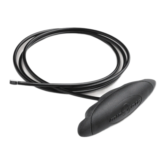
A
1854125
MKA-49 CABLE AND HANDLE
B
CABLE AND HANDLE
✖
2
2371407
CABLE, ROPE HANDLE
4
2280400
PULL GRIP,SOFT, TOP
6
2280405
PULL GRIP,SOFT, BOTTOM
8
2370860
CLEVIS, ROPE HANDLE
10
2372673
PIN-CLEVIS .188 SS
✖ This part is included in an assembly and cannot be ordered individually.
p Not shown on Parts Diagram.
TOOLS AND RESOURCES REQUIRED
• (2) #3 Phillips screwdrivers
ULTREX, FORTREX AND RIPTIDE FORTREX INSTALLATION
Disconnect the Gas Spring
1
WARNING
Moving parts can cut or crush. The gas assist lift
mechanism is under pressure. Disconnect gas spring
before removing motor from mount. Do not engage the
pull grip and rope until gas spring is disconnected.
a.
In order to remove the Bowguard/Steering Module,
the Gas Spring needs to be disconnected. Place the
motor in the stowed position.
1 | minnkotamotors.com
MKA-49 PREMIUM CABLE & HANDLE
Qty.
1
1
1
1
1
1
1
• 1/4" Allen Wrench
4
6
B
2
8
A
10
• Torque Wrench
1854125
• Needle Nose Pliers
©2019 Johnson Outdoors Marine Electronics, Inc.
Advertisement

Summary of Contents for MINN KOTA MKA-49
- Page 1 MKA-49 PREMIUM CABLE & HANDLE 1854125 Item / Part # Description Qty. Assembly 1854125 MKA-49 CABLE AND HANDLE CABLE AND HANDLE ✖ 2371407 CABLE, ROPE HANDLE 2280400 PULL GRIP,SOFT, TOP 2280405 PULL GRIP,SOFT, BOTTOM 2370860 CLEVIS, ROPE HANDLE 2372673 PIN-CLEVIS .188 SS ✖...
- Page 2 To disconnect the Gas Spring, locate the Upper Phillips Upper Gas Spring Outer Cylinder Pin. Two Phillips Screws hold the Upper Screw Cylinder Outer Cylinder Cylinder for the Gas Spring in place. Using two #3 Spacer Spacers Phillips screwdrivers, hold the screw at one end of the Upper Cylinder Pin in place.
- Page 3 Remove the 5/16" Allen Screw with a 1/4" Allen Allen Screw with Lock Washer Wrench. The 5/16" Allen Screw is located on the opposite end of the mount from the hinge that opens and closes when the mount is stowed and deployed.
- Page 4 ITEM(S) NEEDED #10 x 1 #8 x 1 Attach the Clevis (Item #8) onto the Cable by Cable End Rope sliding the clevis slot over the cable and sliding the Stop Guide Cable End Stop into the Clevis. Install the Clevis Pin and Retaining Ring (Item #10).
- Page 5 Reinstall the 5/16" Allen Screw and Lock Washer Allen Screw with Lock Washer and tighten to 18 to 20 ft-lbs with a Torque Wrench. Position the motor to the stowed position using the pull grip and rope to disengage the latch bar, allowing the motor to fold into a flat position.
- Page 6 MAXXUM AND RIPTIDE MAXXUM INSTALLATION ITEM(S) NEEDED B x 1 Note how the rope is routed through the Rope Guide, around the Pins, and into the Eye Shaft. The new cable will be routed in the same manner. Rope Guide Eyelet Lower Arm Remove the current rope.
- Page 7 Ring Retaining Ring onto the groove of the Clevis Pin. Clevis For warranty information please visit minnkotamotors.com Minn Kota Consumer & Technical Service 121 Power Drive Johnson Outdoors Marine Electronics, Inc. Mankato, MN 56001 A Johnson Outdoors Company PO Box 8129 Phone (800) 227-6433 ©2019 Johnson Outdoors Marine Electronics, Inc.
- Page 8 CÂBLE ET POIGNÉE DE GAMME SUPÉRIEURE MKA-49 1854125 Article/ Nº de Description Qté Ensemble pièce 1854125 MKA-49 CABLE AND HANDLE CABLE AND HANDLE ✖ 2371407 CABLE, ROPE HANDLE 2280400 PULL GRIP,SOFT, TOP 2280405 PULL GRIP,SOFT, BOTTOM 2370860 CLEVIS, ROPE HANDLE 2372673 PIN-CLEVIS .188 SS...
- Page 9 Pour déconnecter le ressort à gaz, repérez Goupille de Cylindre Bras Cruciforme Ressort Cylindre la goupille de cylindre supérieure. Deux vis Externe Bras Supérieure à Gaz cruciformes retiennent en place le cylindre Externe Entretoise Entretoise supérieur pour le ressort à gaz. Utilisez deux tournevis cruciformes nº...
- Page 10 Retirez la vis hexagonale 5/16 po (7,94 mm) avec Vis Hexagonale Avec une clé hexagonale 1/4 po (6,35 mm). La vis 5/16 Rondelle de Blocage po (7,94 mm) se trouve sur le côté opposé du support depuis la charnière qui s’ouvre et se ferme lorsque le support est arrimé...
- Page 11 ARTICLE(S) REQUIS #10 x 1 #8 x 1 Fixez la manille (article nº 8) sur le câble en Butée de Fin de Câble Guide-corde glissant la fente de la manille par-dessus le câble et en glissant la butée de fin de câble dans la manille. Installez la goupille de la manille et l’anneau de retenue (article nº...
- Page 12 Reposez la vis hexagonale 5/16 po (7,94 mm) et la Vis Hexagonale Avec rondelle de blocage puis serrez entre 18 et 20 pi-lb Rondelle de Blocage (24,4 et 27,1 Nm) avec une clé de serrage. Positionnez le moteur en position arrimée en utilisant la poignée et la corde de traction pour libérer la barre de verrouillage, permettant au moteur de se plier à...
- Page 13 INSTALLATION MAXXUM ET RIPTIDE MAXXUM ARTICLE(S) REQUIS B x 1 Veuillez noter l’acheminement de la corde dans le guide-corde, autour des goupilles et dans l’arbre œil. Le nouveau câble sera acheminé de la même façon. Œillet du Goupille du Bras Retirez la corde actuelle.
- Page 14 Installez l’anneau de retenue dans la rainure de la Retenue Manille goupille de manille. Pour obtenir des renseignements sur la garantie, veuillez visiter minnkotamotors.com Minn Kota Consumer & Technical Service 121 Power Drive Johnson Outdoors Marine Electronics, Inc. Mankato, MN 56001 A Johnson Outdoors Company PO Box 8129 Phone (800) 227-6433 ©2019 Johnson Outdoors Marine Electronics, Inc.
Need help?
Do you have a question about the MKA-49 and is the answer not in the manual?
Questions and answers