Advertisement
Quick Links
DOEPFER
DOEPFER
DOEPFER
DOEPFER
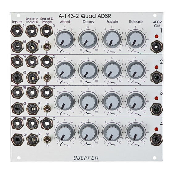
Fig. 1: A-143-2 Controls, Inputs and Outputs
System A-100
1. Introduction
Module A-143-2 contains four independent ADSR-type
envelope generators. Each sub-unit has available the
controls Attack, Decay, Sustain and Release. The three-
position Range switch allows selection of the desired time
range (low - high - medium). The adjustable envelope time
ranges from several minutes to less than 100 microseconds.
On top of this each unit is equipped with three digital outputs
(high/low): "End of Attack (EOA)", "End of Decay (EOD)"
and "End of Release (EOR)". As soon as the criterion is
valid (e.g. end of decay state) the corresponding digital
outputs turns "high". These outputs can be used e.g. to
daisy-chain several ADSR units. For this the digital output in
question (EOA, EOD or EOR) has to be connected to the
Gate input of the following ADSR. Even automatically
running envelopes (pseudo LFOs) or so-called "quadrature
envelopes" with cyclical modulations of several ring-shaped,
daisy-chained ADSRs are possible.
In addition to the obligatory Gate (G) input for envelope
generators each unit has available a Retrigger (Rt) input.
The retrigger turns the direction to "upward" if the envelope
has already reached the decay state while the retrigger
pulse occurs. The Gate inputs 2, 3 and 4 are normalled to
Gate input 1, i.e. the Gate input 1 is connected to the
switching contacts of the other inputs. Thus only one Gate
signal at Gate input 1 can be used to trigger all four units
simultaneously.
The envelope outputs are displayed with LEDs.
Quad ADSR A-143-2
1
Advertisement

Related Manuals for DOEPFER A-143-2


Summary of Contents for DOEPFER A-143-2
- Page 1 Gate input 1, i.e. the Gate input 1 is connected to the switching contacts of the other inputs. Thus only one Gate signal at Gate input 1 can be used to trigger all four units simultaneously. The envelope outputs are displayed with LEDs. Fig. 1: A-143-2 Controls, Inputs and Outputs...
-
Page 2: Basic Principles
When the envelope level reaches about +0.5V the EOR output turns high. The retrigger behaviour of the A-143-2 is different compared to other envelope generators. During the attack phase the envelope cannot be retriggered or reset. During the decay phase the envelope direction changes if a positive edge appears at the retrigger input (i.e. - Page 3 System A-100 Quad ADSR A-143-2 DOEPFER DOEPFER DOEPFER DOEPFER 3. Overview § " & Fig. 5: A-143-2 front panel...
-
Page 4: Inputs And Outputs
Quad ADSR A-143-2 System A-100 DOEPFER DOEPFER DOEPFER DOEPFER Controls: Inputs and Outputs: Range : range switch low – high – medium gate input (gate inputs 2…4 are normalled to gate input 1) Attack : attack control " End of A :... -
Page 5: Controls, Inputs And Outputs
Attack : attack control These outputs can be used to trigger other A-100 modules Decay : decay control (or another unit of the A-143-2) synchronized to the ADSR Sustain : sustain control envelope generated by the A-143-2. Release : release control These controls define the ADSR shape. - Page 6 DOEPFER DOEPFER DOEPFER 4. User Examples The A-143-2 is suitable for all kinds of modulations where envelope generators are used. Please refer to the manuals of other envelope generators (e.g. A-140, A-141, A-142). Cyclically triggered envelope generators The EOD output of each unit is patched to the gate input of the succeeding unit.
Need help?
Do you have a question about the A-143-2 and is the answer not in the manual?
Questions and answers