
Summary of Contents for RPM MPQ Series
- Page 1 MPQ Manufacturing Programmer User's Guide March, 2016 • MPQ-PSoC • MPQ-Z8 • MPQ-C2 • MPQ-AVR • MPQ-AVR32 • MPQ-ARM RPM Systems Corporation Redmond, Washington, USA (425)869-3901 www.rpmsys.com...
-
Page 2: Table Of Contents
4.0 Interfacing MPQ with Automated Test Equipment ..........22 4.1 Control Connector Signal Description ..................22 4.1.1 Active# Control ........................22 4.1.2 ATE Pass/Fail Status ........................ 24 4.1.3 ATE OptionSelection ......................24 4.1.4 ATE Option Setup ......................... 24 March, 2016 Page 2 RPM Systems Corporation... - Page 3 F.1.1 Device Type .......................... 38 F.1.2 Target Voltage ........................38 F.1.3 Mode ............................ 38 F.1.4 Target Frequency ........................39 F.1.5 SPI/JTAG Protocol Select ..................... 39 F.2 Programming Options ........................39 F.2.1 Fuse Values .......................... 40 March, 2016 Page 3 RPM Systems Corporation...
- Page 4 G.1.3 Mode ........................... 45 G.2 Programming Options ......................... 45 G.2.1 Fuse Values .......................... 45 G.2.2 User Memory Programming ....................46 G.2.3 Security Bit Programming ..................... 47 G.3 - Target Cable Connections ....................... 47 March, 2016 Page 4 RPM Systems Corporation...
-
Page 5: Mpq Overview
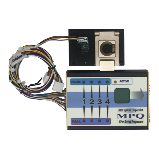
A Target Cable assembly is provided with MPQ which connects its Target port to the circuit board(s) containing the ISP devices to be programmed. RPM offers several termination options for the target end of Target Cables depending upon the particular microcontroller being supported. Target connector options and pin assignments are outlined in the appendices of this manual. - Page 6 While programming is in progress, the MPQ's Active LED will be lit. Upon completion of programming, the Active LED will be doused, and completion status for each of the four ports will be displayed on the Pass/ Fail status LEDs. Disabled ports will not display LED pass/fail status. March, 2016 Page 6 RPM Systems Corporation...
-
Page 7: Mpq Setup And Operation
MPQ's serial interface. If you wish to use a USB to seral adapter with your MPQ, please contact RPM Systems for recommended products, or to purchase an adapter from us directly. 2.3 Starting MP Manager Software and Connecting to MPQ With MPQ powered on and connected the host PC as outlined in the previous section, start the MP Manager software on the host PC (Start/MP Manager/MP Manager). -
Page 8: Loading Image Files Into Mpq Flash
.hex file which was created using the development software for the particular microcontroller supported by your MPQ. Once you have selected the image, MPQ reads the .hex file and verifies that it is March, 2016 Page 8 RPM Systems Corporation... -
Page 9: Selecting Programming Parameters
Once the Load Image dialog is open, you may choose a different image file by clicking on the ellipses next to the Image File. This will reopen the file browse box. The Image Number shown in the Load Image dialog is the number of the image bank selected in the Image March, 2016 Page 9 RPM Systems Corporation... - Page 10 Images in any of the four banks may also be replaced using this process. March, 2016 Page 10 RPM Systems Corporation...
-
Page 11: Multiple Files
Once File, Option and Device selections have been made, the set of selections can be saved as a Project, by clicking on the Save Project button. This will save the file, option and device selection infomration in a Project File, which can subsequently be opened from the Image Manager. March, 2016 Page 11 RPM Systems Corporation... -
Page 12: Security Settings
The security settings for each image, as well as the number of cycles remaining for restricted-count images, are shown in the Image Manager. 2.4.5 Serialization Some MPQ programmers support serialization of the programmed devices. This feature allows the opera- March, 2016 Page 12 RPM Systems Corporation... - Page 13 Image Manager window by selecting the image bank, then selecting View Serialization from the Image menu, or by right-clicking on the image in the Image Manager, and select- ing View Serialization from the popup menu. March, 2016 Page 13 RPM Systems Corporation...
-
Page 14: Deleting Images From Programmer Flash
Programming Manager by selecting the Programming Manager tool bar button, or by selecting the View/ Programming Manager option from the MP Manager menu bar. This will cause the Programming Manager window to be opened. March, 2016 Page 14 RPM Systems Corporation... - Page 15 Program button to start each new cycle. If you would like to switch images, you can do so by switching to the Image Manager window, selecting a different image, then switching back to the Programming Manager window. It is not necessary to close and reopen the Programming Manager. March, 2016 Page 15 RPM Systems Corporation...
-
Page 16: Enabling And Disabling Target Ports
"Checksum Verify" box in the Program Manager window, the operator can elect to have MPQ verify programming by this method, rather than performing a complete read-verify. 2.6.5 Programming Options March, 2016 Page 16 RPM Systems Corporation Some devices offer programming options, such as memory protection features, oscillator selection, etc.,... -
Page 17: Reading Images From Target Devices
Once you have made your selections, click the Read Image button to read the device and program the image into MPQ Flash. While the image is being read, status will be displayed in the Target Port frame. March, 2016 Page 17 RPM Systems Corporation... -
Page 18: Uploading Images From Mpq
Programming Manager. Finally, you will be able to select the desired image bank for each programmer. Once you have selected the desired parameters, simply click the Program button to initiate programming of the entire array. March, 2016 Page 18 RPM Systems Corporation... - Page 19 MPQ Manufacturing Programmer User's Guide March, 2016 Page 19 RPM Systems Corporation...
-
Page 20: Stand-Alone Device Programming
Once you have selected the desired image and port-enable parameters for stand-alone operation, select Configure/Set Defaults from the MP Manager menu bar. This will cause your selections to be loaded and stored in the MPQ, and used as the default settings for stand-alone operations. March, 2016 Page 20 RPM Systems Corporation... - Page 21 MPQ, open the Program Manager, then select the Configure/View Defaults option from MP Manager menu bar. Note that the default settings do not affect operations which are performed in PC-Controlled mode, using MP Manager. View Pushbutton Defaults March, 2016 Page 21 RPM Systems Corporation...
-
Page 22: Interfacing Mpq With Automated Test Equipment
Active# has first returned to the high state. That is, it is necessary for the ATE to release the Active# signal after the start of programming, allowing it to return high upon the March, 2016 Page 22 RPM Systems Corporation... - Page 23 Hold time, Active# asserted to ImageSelEn#, ImageSel[1..0] invalid 10mS Min. ATE Active# Drive Duration Tp Max. 10uS Min. Setup time, PF[4..1] valid to Active# deassertion Tpfsu Programming Time - Device dependent Active# Programming Control March, 2016 Page 23 RPM Systems Corporation...
-
Page 24: Ate Pass/Fail Status
ATE Options from the MPManager menu bar. You will be given the choice of one of the four ATE Options to be used for the setting. The existing ATE Option settings can also be viewed by selecting Configure/ViewATE Options from the MPManager menu bar. March, 2016 Page 24 RPM Systems Corporation... - Page 25 MPQ Manufacturing Programmer User's Guide Set ATE Options March, 2016 Page 25 RPM Systems Corporation...
-
Page 26: Mpq Arrays
This is enabled by using the MPQ's built-in RS-485 communications bus. Essentially, the D+, D- and GND signals of each of the programmers in the array are connected together with March, 2016 Page 26 RPM Systems Corporation... - Page 27 D+, D- and GND signals, respectively, of the other programmers in the array. This is facilitated by the use of the USB Array Interconnect Board, RPM p/n MPQ-AIB-USB, which provides the RS-485 interconnect capability via ribbon cable connectors, as well as an RS-485 to USB interface converter, which allows the entire array to be directly controlled from a standard PC USB port.
-
Page 28: Appendix A - Cypress Psoc And Encore Microcontrollers
MPQ Flash. MPQ-PSoC supports the Cypress Semiconductor PSoCx, enCoRe x and GENx families. A.1.1 Device Type Device Type identifies the particular manufacturer's part number of the PSoC device for which the image March, 2016 Page 28 RPM Systems Corporation... -
Page 29: Target Voltage
EEPROM option causes the device EEPROM to be erased as part of the programming cycle, for those devices for which this is an option. The SWIF option indicates that the programming operation uses the RPM SIWF power-switching board. The setting of the memory protection bits is defined by the Cypress PSoC Develop- ment Tools, and stored in the program image produced by that software. - Page 30 Not Used GND Target GND Black Not Used NOTE: The GND signal must be common amongst the four target ports when connected to the programmer. All GNDs are tied together internal to MPQ. March, 2016 Page 30 RPM Systems Corporation...
-
Page 31: Appendix B - Zilog Z8 Encore! And Zlf645
MPQ Flash. B.1.1 Device Family and Type Device Family selection can be Z8-Encore, ZNeo of ZLF645. Device Type identifies the particular March, 2016 Page 31 RPM Systems Corporation... -
Page 32: Target Voltage
Z8 Encore Options window. Select the programming options prior to clicking the "Load Image" button. The parameters that can be modified in this window are device dependent, so be certain to select the March, 2016 Page 32 RPM Systems Corporation... -
Page 33: Target Cable Connections
The following table shows the pin assignments for the various connectors. One Target Cable assembly provides four sets of target programming signals. March, 2016 Page 33 RPM Systems Corporation... - Page 34 Not Used GND Target GND Black Not Used NOTE: The GND signal must be common amongst the four target ports when connected to the programmer. All GNDs are tied together internal to MPQ. March, 2016 Page 34 RPM Systems Corporation...
-
Page 35: Appendix D - Silicon Labs C2 Microcontrollers
Device Type identifies the particular manufacturer's part number of the device for which the image being loaded is intended. Select the proper device from the dropdown list. MPQ will use this information prior to programming to verify the device ID in the part to be programmed. March, 2016 Page 35 RPM Systems Corporation... -
Page 36: Target Voltage
1.0 Kohm. If pin sharing isolation is not required in a given design, it is not necessary to include the isolation resistors, and the iso_c2d and iso_csck connections may be omitted. March, 2016 Page 36 RPM Systems Corporation... - Page 37 Violet Not Used Target GND Black Not Used NOTE: The GND signal must be common amongst the four target ports when connected to the programmer. All GNDs are tied together internal to MPQ. March, 2016 Page 37 RPM Systems Corporation...
-
Page 38: Appendix F - Atmel Avr
There are two Mode selections available for AVR, "Reset" and "Run". The Mode selection determines whether the target system will be held in reset at the completion of a program cycle ("Reset"), or be reset and then permitted to begin code execution ("Run"). March, 2016 Page 38 RPM Systems Corporation... -
Page 39: Target Frequency
Note that some devices do not support both inter- faces and, as a result, both options may not be available. F.2 Programming Options The AVR family offers a variety of programming options which can be selected via MP Manager when the March, 2016 Page 39 RPM Systems Corporation... -
Page 40: Fuse Values
Intel HEX formatted file. You may also provide a name for the image by typing up to 20 characters in the "Image Name" field. The image name defaults to the file name of the selected image file. March, 2016 Page 40 RPM Systems Corporation... -
Page 41: Osccal Programming
Atmel for SPI and JTAG programming. The following tables show the pin assignments for the various connectors. Note that one Target Cable assembly provides four sets of target programming signals. March, 2016 Page 41 RPM Systems Corporation... - Page 42 Not Used GND Target GND Black Not Used NOTE: The GND signal must be common amongst the four target ports when connected to the programmer. All GNDs are tied together internal to MPQ. March, 2016 Page 42 RPM Systems Corporation...
- Page 43 TMS Program Mode Select Green GND Target GND Black Not Used NOTE: The GND signal must be common amongst the four target ports when connected to the programmer. All GNDs are tied together internal to MPQ. March, 2016 Page 43 RPM Systems Corporation...
-
Page 44: Appendix G - Atmel Avr32
Select the voltage at which the target system Vio will be operating during the programming of the device. MPQ will use this information to verify that the target power is at the proper level before beginning the program- March, 2016 Page 44 RPM Systems Corporation... -
Page 45: Mode
To modify the fuse values, click on the field that you would like to modify, and an option box will appear, enumerating the available options and allowing you to choose one. March, 2016 Page 45 RPM Systems Corporation... -
Page 46: User Memory Programming
Intel HEX formatted file. You may also provide a name for the image by typing up to 20 characters in the "Image Name" field. The image name defaults to the file name of the selected image file. March, 2016 Page 46 RPM Systems Corporation... -
Page 47: Security Bit Programming
0.1" x 0.1" spaced 10-pin programming connectors specified by Atmel JTAG programming. The following tables shows the pin assignments for the various connectors. Note that one Target Cable assembly provides four sets of target programming signals. March, 2016 Page 47 RPM Systems Corporation... - Page 48 TMS Program Mode Select Green GND Target GND Black Not Used NOTE: The GND signal must be common amongst the four target ports when connected to the programmer. All GNDs are tied together internal to MPQ. March, 2016 Page 48 RPM Systems Corporation...
Need help?
Do you have a question about the MPQ Series and is the answer not in the manual?
Questions and answers