Advertisement
Quick Links
Build Your Own Clone
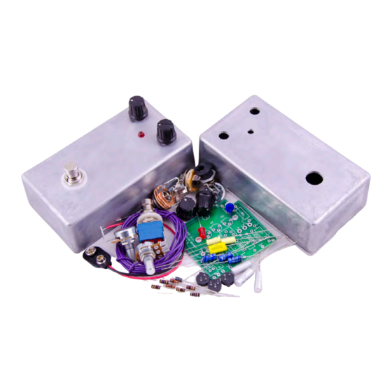
E.S.V. 2-Knob Bender
Kit Instructions
Warranty:
BYOC, Inc. guarantees that your kit will be complete and that all parts and components
will arrive as described, functioning and free of defect. Soldering, clipping, cutting,
stripping, or using any of the components in any way voids this guarantee. BYOC, INC
guarantees that the instructions for your kit will be free of any majors errors that would
cause you to permanently damage any components in your kit, but does not guarantee
that the instructions will be free of typos or minor errors. BYOC, INC does not
warranty the completed pedal as a whole functioning unit, nor do we warranty any of the
individual parts once they have been used. If you have a component that is used, but feel
it was defective prior to you using it, we reserve the right to determine whether or not the
component was faulty upon arrival. Please direct all warranty issues to:
sales@buildyourownclone.com This would include any missing parts issues.
Return:
BYOC, Inc. accepts returns and exchanges on all products for any reason, as long as they
are unused. We do not accept partial kit returns. Returns and exchanges are for the full
purchase price less the cost of shipping and/or any promotional pricing. Return shipping
is the customer's responsibility. This responsibility not only includes the cost of
shipping, but accountability of deliver as well. Please contact
sales@buildyourownclone.com to receive a return authorization before mailing.
Tech Support:
Advertisement

Summary of Contents for BYOC E.S.V. 2-Knob Bender
- Page 1 This would include any missing parts issues. Return: BYOC, Inc. accepts returns and exchanges on all products for any reason, as long as they are unused. We do not accept partial kit returns. Returns and exchanges are for the full purchase price less the cost of shipping and/or any promotional pricing.
- Page 2 That being said, we will do our best to help you as much as we can. Our philosophy at BYOC is that we will help you only as much as you are willing to help yourself. We have a wonderful and friendly DIY discussion forum with an entire section devoted to the technical support and modifications of BYOC kits.
-
Page 3: Table Of Contents
2-Knob Bender Kit Instruction Index Parts Checklist………………………....…..page 6 Populating the Circuit Board……....…...…..page 8 Main PCB Assembly..........page 16 Wiring………………………………......page 19 Installing the IC/Finishing up…………………..page 25 Operation Overview...........page 26 Schematic..............page 27... -
Page 4: Parts Checklist
Parts Checklist for E.S.V. 2-Knob Bender Kit Resistors: 1 - 470Ohm (Yellow/Purple/Brown/Gold) 1 - 4k7 (Yellow/Purple/Red/Gold) 1 - 10k (Brown/Black/Orange/Gold) 1 - 47k (Yellow/Purple/Orange/Gold) 2 - 100k (Brown/Black/Yellow/Gold) 1 - 1M (Brown/Black/Green/Gold) Visit www.byocelectronics.com/resistorcodes.pdf for more information on how to differentiate resistors. - Page 5 Potentiometers: SNAP THE SMALL TABS ON THE TOP OF THE POTS OFF WITH A PAIR OF NEEDLE NOSE PLIERS 1 - A100k (LEVEL) 1 - B1k (ATTACK) 1 - 25k Trimpot Hardware: 1 - predrilled enclosure w/ 4 screws 1 - 2-Knob Bender circuit board 1 - 3pdt footswitch 2 - Knobs 1 - AC adapter jack...
-
Page 6: Populating The Circuit Board
Populating the Circuit Board Step 1: Add all the resistors. Resistors are not polarized and can be inserted in either direction. - Page 7 Add the transistor sockets sockets. ONLY SOLDER THE Step 2: SOCKET! The sockets get soldered to the PCB. The transistors get inserted into the sockets. The actual transistors never get soldered. You will insert the transistors into the sockets after the entire pedal has been built. Match the tabs on the sockets to the tabs on the tabs on the PCB screenprint.
- Page 8 Step 3: Add the trimpot. There are 5 holes on the PCB, but only three leads on the trimpot. Do not be alarmed by this, this is to accommodate different trimpot sizes. Your trimpot will fit neatly into three of the five holes. Once you have installed your transistors, adjust the bias trimpot to taste.
- Page 9 Step 4: Add the film capacitors. These are non-polarized so it can go in either direction.
- Page 10 Step 5: Add the electrolytic capacitors. These ARE polarized, meaning there is a positive and negative end. The positive end will have a little groove in the body, like the screenprint outline.
- Page 11 Step 6: Add the battery snap. Thread the solder ends of the battery snap through the strain relief holes from the bottom solder side of the PCB and out through the top. Insert the solder ends of the battery snap wires into the topside of their respective solder pads.
- Page 12 Step 7: Add wires to the IN, OUT, RING, and two Ground eyelets. Start by cutting four 2.5” pieces of wire, and four 1.5” piece. Strip 1/4” off each end and tin the ends. Tinning means to apply some solder to the stripped ends of the wires. This keeps the strands from fraying and primes the wire for soldering.
-
Page 13: Main Pcb Assembly
Main PCB Assembly Step 1: Mount the AC adapter jack to the enclosure. Your kit may come with either an external thread or internal thread. Don’t get confused by this. They still function exactly the same. You just thread the external nut on the outside and the internal nut on the inside. - Page 14 SOLDER ANYTHING YET!!! The LED will have one lead that is longer than the other. THIS WILL GO INTO THE SQUARE SOLDER HOLE.
- Page 15 Step 3: Hold the PCB in one hand so that the component side of the PCB is in the palm of your hand and the bottom side with the pots, toggle switch and LED is facing up. Now use your other hand to guide the predrilled enclosure onto the PCB assembly so that the pots and LED all go into their respective holes.
-
Page 16: Wiring
Wiring Step 6: Connect the TIP (negative) terminal of the DC adaptor jack to the eyelet on the PCB labeled “-“. Connect the SLEEVE of the DC adaptor jack to the eyelet on the PCB labeled “+” farthest to the right. Connect the battery disconnect terminal of the DC adaptor jack to the second eyelet on the PCB labeled “+”... - Page 17 Stereo (input) Jack Mono (output) Jack Step 1: Install the 1/4” jacks to the enclosure.
- Page 18 Step 2: Install the footswitch. Orient the footswitch so that the flat sides of the solder lugs are like the diagram below. NOTE: There are no actual number markings on the footswitch. There are two correct ways you can orient the footswitch. They are both 180 degrees of each other.
- Page 19 FOOT SWITCH SOLDER LUG DESIGNATIONS Step 3: Wiring the foot switch. Make a jumper between lugs 3 & 6 from clippings from the resistors. • Simply use your needle nose pliers to make a U shape & insert into lugs 3 &...
- Page 20 Cut two 1” pieces of wire. Strip 1/8” off each end and tin. These will • be used to connect lugs/eyelets 1 & 7 Cut three 1.25” pieces of wire. Strip 1/8” off each end and tin. This • will be used to connect lugs/eyelets 2, 5, & 8 Step 4: Install the foot switch into the enclosure if it isn’t already.
- Page 21 eyelet goes to the tip of the stereo jack. The wire from the RING eyelet goes to the ring of the stereo jack. The wire from the eyelet closest to the stereo ê jack goes to the sleeve of the stereo jack. The wire from the OUT eyelet goes to the tip of the mono jack.
- Page 22 Finishing Touches Add the OC75 transistors to their sockets. DO NOT SOLDER THEM!!!!!!!! DO NOT CLIP THEIR LEADS!!!!!!!!!!! Soldering or clipping them will void your warranty. We will not accept returns is they are used. Install your transistors into their sockets with full leads to test the pedal first. When you know that your pedal works and sounds the way you expect it to, then clip the leads and re-install the transistors.
-
Page 23: Operation Overview
Operating Overview LEVEL: Controls the output volume. ATTACK: This is essentially your fuzz control. Power supply: 9V battery or 2.1mm negative tip... - Page 24 Please visit http://byocelectronics.com/board For any technical support Copyright 2018 BYOC, Inc.
Need help?
Do you have a question about the E.S.V. 2-Knob Bender and is the answer not in the manual?
Questions and answers