Summary of Contents for FLARM GPS-FilterBox 2.0
- Page 1 GPS-FilterBox 2.0 Connect your ADS-B now! Manual Version 1.1 July 2012 Introduction | GPS-FilterBox 2.0 Manual...
-
Page 2: Table Of Contents
GPS NMEA-sentences. The main purpose is to enable the ADS- Typical use ................ 5 B functionality of any transponder without the need for an extra Overview ................6 GPS device. Instead existing devices like a FLARM can provide position data. Installation ............... 7 4.1. -
Page 3: Typical Use
The design enables you to connect a Mode S transponder to your FLARM ánd a PDA/PNA as well as your regular FLARM display. In double seaters the GPS-FilterBox can be connected to both displays and a transponder, or if you wish, your PDA/PNA on the filtered output instead of a transponder. -
Page 4: Installation
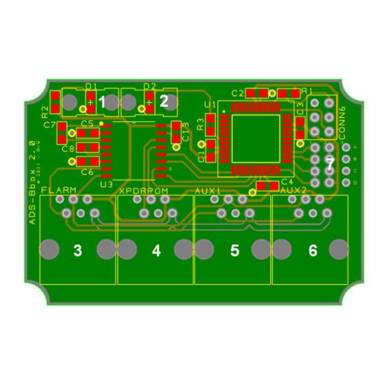
The GPS-FilterBox is configured and ready to go right out of the box. To start using your GPS-FilterBox, please connect the following: 1. Connect your input device -for example a FLARM- to the FLARM connector. Be sure the values on pin 1-6 do not exceed the maximum ratings as specified in chapter 6: Technical Data. -
Page 5: Typical Use
Configuration Input baudrate 19200 bps Output baudrate 4800 bps Filter RMC sentences Pass GGA sentences Block GSA sentences Block On/off switch Enabled Table 2: Standard configuration Figure 4: Typical use GPS-FilterBox 2.0 Manual | Installation Configuration | GPS-FilterBox 2.0 Manual... -
Page 6: Configuration Options
Output baudrate 4800/9600/19200/ 0/1/2/3/4 Be aware that the GPS-FilterBox still needs to be powered, either by 38400/115200 bps an external power supply, or by connecting a FLARM unit to the Filter On/Off FLARM input on the GPS-FilterBox. RMC sentences Pass/Block... - Page 7 Be aware that the baudrate can differ if you configured the device before. If you are not able to connect, you may consider resetting the device to factory default. Figure 8: Putty configuration Figure 7: GPS-FilterBox Tool GPS-FilterBox 2.0 Manual | Configuration Configuration | GPS-FilterBox 2.0 Manual...
-
Page 8: Reset To Factory Default
Remove the connection between B1 and B2. Your GPS-FilterBox is Figure 9: Example of the help-screen in Putty now ready for use with the default settings. Figure 10: Example reset connection (black wire) GPS-FilterBox 2.0 Manual | Configuration Configuration | GPS-FilterBox 2.0 Manual... -
Page 9: Reset Using Software
Press 'x' to reset to factory defaults. A message confirming the defaults are set will appear. Press 'r' to reboot or interrupt the power supply for a few seconds. GPS-FilterBox 2.0 Manual | Configuration Configuration | GPS-FilterBox 2.0 Manual... -
Page 10: Technical Data
Table 6: RJ12 connectors pinout Config pin Description Connection On/Off switch A1-A2 = off Reset B1-B2 = reset Start Bootloader C1-C2 = start Not implemented A2…D2 A3…D3 Table 7: Configuration matrix GPS-FilterBox 2.0 Manual | Technical Data Disclaimer | GPS-FilterBox 2.0 Manual... -
Page 11: Limitations
Under the terms of this limited warranty, the GPS-FilterBox manufacturer shall not be held responsible for any cost resulting from such a modification/adaptation. GPS-FilterBox 2.0 Manual | Limitations Limited Warranty | GPS-FilterBox 2.0 Manual... - Page 12 Conducting firmware updates; • Damage/defects caused by acts of God/Nature (accident, • fire, flood, etc) or any other condition that is beyond the control of the GPS-FilterBox manufacturer. GPS-FilterBox 2.0 Manual | Limited Warranty...


Need help?
Do you have a question about the GPS-FilterBox 2.0 and is the answer not in the manual?
Questions and answers