Table of Contents
Advertisement
Quick Links
Advertisement
Table of Contents

Subscribe to Our Youtube Channel
Summary of Contents for Laski VD 500
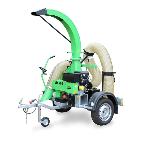
- Page 1 OPERATING INSTRUCTIONS LEAVES EXHAUSTER VD 500 Version 03. 2020...
-
Page 2: Foreword
It is very important for you and your work safety to understand all instructions given in this manual. The firm Laski spol. s r.o. does not bear any responsibility for any claims resulting from disobedience to the instructions given in this manual. -
Page 3: Table Of Contents
......................2 OREWORD PRODUCT IDENTIFICATION ................6 ......................7 TILISATION ..............11 RANSPORT OF RODUCT ANDLING TRANSPORT SAFETY ON PUBLIC ROADS ..........13 Transport Position ..................14 Trailer coupling/uncoupling ................14 Putting aside and parking ................15 Trailer loading ....................15 ................ -
Page 6: Product Identification
Product Identification Our product is identified with its serial number stamped on the type plate. Pay your attention also to the type plate on the combustion engine. Upon take-over of the product we recommend you to fill required data in the following form concerning the given product and your dealer. -
Page 7: Utilisation
Utilisation The leaves exhauster is designed for collecting of leaves or short-cut (mowed) grasses in places where gathered after upkeep and cleaning of parks and green areas. Not Allowed Use This exhauster is designed only for collecting of aforesaid materials and not allowed for evacuation of metal particles, woody pieces, wood dust, sand, grit, broken glass, textiles etc. - Page 8 Before transport put the suction hose in its holders around the machine to avoid its overhanging in side face. Keep the given traffic rules and instructions for vehicle outlines and lights. Before transport fix the discharge duct hose against motion. Couple the exhauster to a towing vehicle properly and check its proper coupling.
- Page 9 Fill up the fuel tank before working and only if the machine is turned off. To fill up the fuel tank use always a proper filling funnel with extension. Do not fill the fuel tank while the engine is hot or still running. Do not use petrol as a cleaning agent.
- Page 10 Work Safety Symbols This article introduces work safety symbols (pictographs) used on this machine. Under the given position number there is their location on the machine. These work safety symbols warn the operator against risks connected with the machine use. Your respect to the symbol meanings is a precondition for your work safety. The user is obliged to keep all the work safety symbols legible, clear and undamaged.
-
Page 11: Transport Of Product/Handling
Read this While maintaining, Warning! Electric Start the machine operating manual servicing or voltage with the switch key before use. repairing always only. Do not short follow the manual circuit its contacts. and take always the switch key out of ignition. Warning! Fuel is Warning! Hot parts Warning! Turning... - Page 12 Uncouple the exhauster always on compact, flat and sufficiently bearing surface only. It is not allowed to put any objects or tools on the machine. Never pile exhausters up on each other. Keep the towing bracket ball or the drawbar eye clean (free of sand etc.);...
-
Page 13: Transport Safety On Public Roads
The fan wheel space is protected against access by a hinged cover with a terminal switch. CAUTION!! If the engine is turned off, the fan wheel runs freely out. Do not open the spiral casing of the fan wheel until it stops. Controls The leaves exhauster can be controlled by means of controls installed on the engine console. -
Page 14: Transport Position
Always before coming to a public road it is necessary to remove all mud and accumulated sediments, especially from trailer tires. Transport Position First make the machine ready for transport: turn the engine off; couple the trailer on the towing bracket ball, or ... -
Page 15: Putting Aside And Parking
For a braked variant: connect the brake safety rope to the buffer, frame or towing bracket in rear of the towing vehicle. This rope of the overrun brake system should be led directly to the towing vehicle and freely for all reciprocal movements both of the trailer and the vehicle. -
Page 16: Trailer Checks Before Ride
While loading on a transport vehicle, no persons are allowed to be under the trailer or in its close vicinity – risk of accidents. Trailer checks before ride The driver is obliged to carry out the following checks, in particular: ... -
Page 17: Storage
Machine ready for transport Set the discharge duct forwards Put the suction hose in holders Put the hose nozzle in its holder and secure it with a clip and secure it with a cotter pin Before starting the battery should be fully charged. Remove the battery and let have it recharged by an authorised person. -
Page 18: Before Putting Into Operation
Discharge the used oil into a special bin. Dispose used oil and used filters always in accordance with relevant valid laws and local regulations. Remove any spilled oil and clean all oily spots. Always put the machine aside on a flat and solid floor and block its wheels against unwilling motion by means of scotch blocks. -
Page 19: Before Putting Into Operation
Check the engine oil level with a dipstick and refill if necessary. The oil level should be between both marks (MIN and MAX). Check the suction hose for tightness – any untightness reduces suction performance essentially (wear, damage). For putting the suction hose on its adapters use always binding bands. In case of any damage on the exhauster contact your dealer or authorised service. - Page 20 Any servicing can be done only if the machine was put out of operation and its chassis blocked against unwilling motion. In case of a braked trailer, use its parking brake or chock both travelling wheels. Do not step on the chassis frame! It is strictly forbidden to test the suction draw or air flow by extremities.
-
Page 21: Putting Out Of Operation
At cold starting, especially in winter time, do not increase the engine speed but first let the engine running in idle speed to warm up. Do not leave the machine unattended. At the first start there is much more air in the intake manifold and on this account the engine may not roar to life immediately when turning the switch key for the first time. - Page 22 Is strictly off limits test run of the exhauster puting near the suction hole to parts of the human bodies , stoking limbs to the suction-fan , also to the flow of air. Set the exhauster so that the suction hose has optimal access to the leaves to be sucked.
-
Page 23: Noise And Vibrations
Avoid spillage while filling fuel. If any fuel is spilled or overflowed then wipe off the spots immediately and let the fuel evaporate. - Do not adjust the discharge duct or its end piece anyhow while the machine is being in operation. Do not put your hand in the air and leaves flow. -
Page 24: Technical Description
from operation. To touch these components first wait for 10 min at least to let them cool down. EXPLOSIVE VAPOURS Refer to your local fuel supplier for the MSDS sheet. Fuel used for this engine is inflammable material with its class of danger I. If fuel refilling is required then put the machine out of operation and let the engine cool down. -
Page 25: Driving Engine
Driving Engine This exhauster is powered by an air-cooled four-stroke single petrol engine KOHLER CH740 built in the rear part of the machine frame. The engine is equipped with an electric starter. One 12 V battery is installed aside the engine with its metal fuel tank. -
Page 26: Technical Parameters
Technical Parameters Parameter Unit Value Vehicle, type Special trailer, category 01, with leaves exhauster Type Variant A (unbraked) Version Trade mark VD 500 P Overall length 2240 Overall width 1560 Overall height 2350 Wheel base 1530 Wheel track 1375 Weight (operating) Weight (max. -
Page 27: Maintenance
Type Kohler CH 740 four-stroke, air-cooled, twin petrol engine Power output 18,6/3600 min Overhead valves Operating revolutions 3600 Lubrication forced Oil sort 10W-40 Oil charge Oil filter full-flow Fuel unleaded petrol, ON 95 Fuel tank capacity Ignition system magnetoelectric Spark plugs Champion RC 12 YC Spark gap Starter... -
Page 28: Trailer Maintenance
Grease points Fan rotor bedding Discharge duct swivel plate Check up the fan wheel vanes for contingent damages and completeness Fan wheel Trailer maintenance: Check up the trailer daily for good technical condition (before ride) and remove detected faults. The trailer should be ready for operation only in good technical order. -
Page 29: Hot-Dip Galvanized Parts
After first 500 km: - all bolted joints and retighten if necessary Every 5 000 km or every 12 months: - all bolted joints and retighten if necessary - axle, springs, parts for excessive wear or contingent damages and replace them if necessary - wheel bearings are maintenance-free (with permanent grease packing) - exchange them only in case of contingent damage - ball coupler and towing bracket or towing eye and hitch: apply... -
Page 30: V-Belt Tension
It is strictly forbidden to carry out any welding works on the axle, overrun mechanism and coupling device – damaged parts must always be replaced. V-belt tension It is necessary to pay special attention to the routine maintenance and proper belt tension adjustment because the V-belts on this machine transfer the engine torque to the fan wheel. - Page 31 1 – fixing bolts 2 – stretching bolts For belt tension adjustment remove the side cover fixed here over the belt drive. Check up optimal slack of belts. It should be 15,5 mm just in the middle between both pulleys at down pressure of 50 N. If the recommended slack value is exceeded, tighten the belts by means of necessary replacement of the driving engine in its longitudinal grooves.
- Page 32 For proper belt tension first check up also alignment of pulleys (their faces). Align the pulleys (their faces) by means of a straight-edge rule. Pay your attention to this alignment also after any engine displacement. At reassembly do not confuse the RH side pulley (engine) with the LH side pulley (fan).
-
Page 33: Maintenance Intervals
Loosen the locking nuts (3- 2x) on the stretching bolts (2 - 2x) and move the engine in its slot holes as necessary. Go on displacing the engine to set up optimal belt tension/slack of 15,5 mm at down pressure of 50 N. Having reached the recommended belt slack value and proper pulley alignment, retighten the fixing bolts on the engine (1 - 4x) and the locking nuts (3 - 2x). -
Page 34: Failures And Troubleshooting
the locking nut and remove the filter element. Check the air pre-cleaner every 25 working hrs as follows: Loosen the pre-cleaner carefully from its cap, remove deposits from its element and wash it in warm water with a non-foamy detergent. Rinse the filter element with the water, press the water out and dry it up. -
Page 35: Warranty
Engine does Discharged battery Recharge battery not start Broken lead Check up wiring SERVICE No plug sparking Clean/exchange spark plug Fouled fuel filter Change filter element Lack of fuel Refill fuel Low engine oil level Refill oil NOTE: The note "SERVICE" in the "Remedy" column means that this operation should be done by an authorised service only. - Page 36 This warranty does not cover consequences resulted from weather effects. Any warranty claims must be submitted in writing with papers concerning acceptance for warranty or post-warranty repair.
-
Page 37: Service Report
Service Report... - Page 38 Service Report...
- Page 39 Service Report...
Need help?
Do you have a question about the VD 500 and is the answer not in the manual?
Questions and answers