Table of Contents
Advertisement
Quick Links
Архангельск (8182)63-90-72
Астана +7(7172)727-132
Белгород (4722)40-23-64
Брянск (4832)59-03-52
Владивосток (423)249-28-31
Волгоград (844)278-03-48
Вологда (8172)26-41-59
Воронеж (473)204-51-73
Екатеринбург (343)384-55-89
Иваново (4932)77-34-06
Ижевск (3412)26-03-58
Казань (843)206-01-48
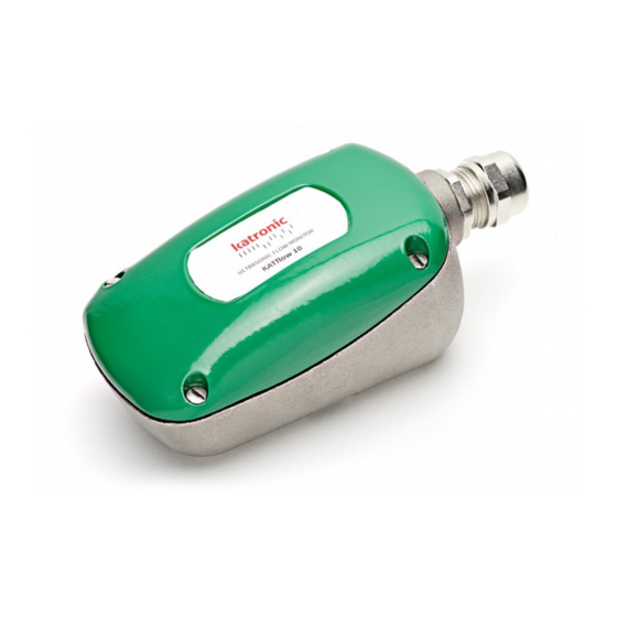
Non-invasive Ultrasonic Flow Monitor
KATflow 10
По вопросам продаж и поддержки обращайтесь:
Калининград (4012)72-03-81
Калуга (4842)92-23-67
Кемерово (3842)65-04-62
Киров (8332)68-02-04
Краснодар (861)203-40-90
Красноярск (391)204-63-61
Курск (4712)77-13-04
Липецк (4742)52-20-81
Магнитогорск (3519)55-03-13
Москва (495)268-04-70
Мурманск (8152)59-64-93
Набережные Челны (8552)20-53-41
сайт: www.katflow.nt-rt.ru || эл. почта: ktf@nt-rt.ru
Нижний Новгород (831)429-08-12
Новокузнецк (3843)20-46-81
Новосибирск (383)227-86-73
Орел (4862)44-53-42
Оренбург (3532)37-68-04
Пенза (8412)22-31-16
Пермь (342)205-81-47
Ростов-на-Дону (863)308-18-15
Рязань (4912)46-61-64
Самара (846)206-03-16
Санкт-Петербург (812)309-46-40
Саратов (845)249-38-78
M-10-0000-E
Смоленск (4812)29-41-54
Сочи (862)225-72-31
Ставрополь (8652)20-65-13
Тверь (4822)63-31-35
Томск (3822)98-41-53
Тула (4872)74-02-29
Тюмень (3452)66-21-18
Ульяновск (8422)24-23-59
Уфа (347)229-48-12
Челябинск (351)202-03-61
Череповец (8202)49-02-64
Ярославль (4852)69-52-93
Advertisement
Table of Contents

Summary of Contents for Katronic KATflow 10 Series
- Page 1 По вопросам продаж и поддержки обращайтесь: Архангельск (8182)63-90-72 Калининград (4012)72-03-81 Нижний Новгород (831)429-08-12 Смоленск (4812)29-41-54 Астана +7(7172)727-132 Калуга (4842)92-23-67 Новокузнецк (3843)20-46-81 Сочи (862)225-72-31 Белгород (4722)40-23-64 Кемерово (3842)65-04-62 Новосибирск (383)227-86-73 Ставрополь (8652)20-65-13 Брянск (4832)59-03-52 Киров (8332)68-02-04 Орел (4862)44-53-42 Тверь (4822)63-31-35 Владивосток (423)249-28-31 Краснодар...
- Page 2 Page 2...
-
Page 3: Table Of Contents
Contents Introduction............ Principle of Operation........Applications..........…... Installation..........…. Set up Procedure (KATflow 10-01 only) ..Alarm Modes......... Entering the Setup Mode....Selecting the Alarm Mode.... Setting the Alarm Set Point..Alarm Conditions..…………….. Current Output....... Voltage Output....... Diagnostics........Operation at Elevated Temperatures..…. Cable Specification........…... -
Page 4: Introduction
The latest, proven ultrasonic techniques are employed to provide repeatable and reliable switching points. The KATflow 10 series can be installed and set up in minutes without disturbing the process it is monitoring. The microprocessor control allows the set up procedure to be completed in a few seconds as well as providing fault diagnosis and alarm indication. -
Page 5: Principle Of Operation
The KATflow 10 series converts this frequency shift into an analogue voltage which is propor- tional to the flow rate. -
Page 6: Applications
Applications For the best results the KATflow 10 series can be applied where: • there is a full pipe flow. • the pipe material is steel, iron, plastic or glass but not con- crete, rubber or flexible plastic pipes. •... - Page 7 Page 7...
-
Page 8: Installation
Installation • Before installation ensure that the application and in- tended mounting position are compatible with the re- quirements in the previous section and that the power supply is capable of supplying the rated voltage and current (22 to 36 V dc @ 150 mA) and is fused cor- rectly (250 mA). - Page 9 Figure 2. Correct alignment on pipe • The sensor is strapped to the pipe using suitable metal banding (11 mm wide maximum). Prior to mounting the sensor on the pipe ensure that the length of banding will go around the pipe and then thread one end through the slot in the base of the sensor.
- Page 10 Figure 3. Cable End Preparation ble specification page 19) with the end already pre- pared, see figure 3, through the cable gland and wire the sensor as shown in figure 4. • KATflow 10-01 only – Tighten the cable gland. Figure 4.
- Page 11 Note: The KATflow 10-02 is fitted with an integral cable, it is not possible to remove the lid. The sensor should be connected as shown in figure 5 Figure 5. KATflow 10-02 wiring details Apply power to the sensor. • KATflow 10-01 only - both LED’s should be illumi- nated for 30 secs.
-
Page 12: Set Up Procedure (Katflow 10-01 Only)
Set up Procedure (KATflow 10-01 only) Note: There is no set up procedure for the KATflow 10-02 . Once the unit is wired up and the power applied, the analogue voltage output provides a signal that is proportional to the flow rate in the pipe. - Page 13 Figure 6 - Alarm Low operating mode outside the normal flow range. Alarm High - in this mode the KATflow 10-01 will go into alarm when the flow rate rises above the alarm set point, see figure 8. For example to detect when a flow exceeds a safe limit. Figure 7 - Out of bounds alarm mode Once the KATflow 10-01 has been installed on the pipe and all the necessary electrical connections made, (“Installation”, page...
-
Page 14: Entering The Setup Mode
Figure 8 - Alarm High operating mode finished, the set up procedure can commence, if the lid has not been removed you will need to remove it now. Before proceeding with the set up, decide which Alarm Mode and Alarm Set-Point are required. •... -
Page 15: Selecting The Alarm Mode
Selecting the Alarm Mode only) KATflow 10-01 • Select 1 of the 3 Alarm Modes (see previous pages for an explanation) by pressing the button 1, 2 or 3 times. Each button press will cause the green LED to extinguish for 0.5 seconds as confirmation. -
Page 16: Alarm Conditions
70% of normal flow. In alarm high mode a 30% set point will trigger an alarm if the flow exceeds 130% of normal flow. • If the requested Alarm Set Point cannot be set it will default to the closest possible. At some low flow rates the resolution of the flow measurement is insufficient to allow reliable switching if a 10% or 20% Alarm Set Point is requested, the Alarm Set point will then default to 30%. -
Page 17: Voltage Output
prox. 3.5 m/s flow velocity Voltage Output • The range of output voltage is 50 mV to 10 V. The scaling of the voltage output is fixed, 50 mV corresponds to a zero flow condition and 10 V = approx. 3.5 m/s flow veloc- Diagnostics (KATflow 10-01 only) There are several fault conditions that the sensor can detect such as insufficient particles in the fluid (e.g. -
Page 18: Operation At Elevated Temperatures
Operation at Elevated Temperatures If the KATflow 10 series is to be operated in ambient tempera- tures in excess of 55 C, the maximum allowable power supply voltage will need to be de-rated according to the graph below. KATflow 10 MAXIMUM INPUT VOLTAGE... -
Page 19: Cable Specification
“top hat” in the cable gland as shown in figure 2. KATflow 10 series requires minimum power supply parameters of 18 V dc @ 150 mA at the sensor. In order to determine a suitable... -
Page 20: Emc Declaration
EMC Declaration The product described in this manual has been tested and complies with the following European standards: EN50081-1 : 1992 Generic Emission Standard - Residential, Commercial and Light Industry EN50082-2 : 1995 Generic Immunity Standard - Industrial Environ- ment. Note: The product is susceptible to fields greater than 4 V/m at kHz and in the band 1.48 to 1.52 MHz. -
Page 21: Troubleshooting
Troubleshooting Symptom Remedy ⇒ The red LED is illuminated The KATflow 10 cannot detect a flow, check that after the setup procedure has there is flow in the pipe and that the flow is within completed. the rated flow rates as defined i n Table 1, page 7. ⇒... -
Page 22: Technical Specification
Technical Specification: KATflow 10 Outputs KATflow 10-01 1 volt free contact, programmable 1A at 30V dc SPCO 4-20 mA auto scaled 0-10 V dc analogue KATflow 10-02 0-10 V dc analogue Power Requirements 22-36 V dc, 120 mA typically Operating Temperatures C to +85 Ingress Protection Rating IP67 (equivalent to NEMA 6)
Need help?
Do you have a question about the KATflow 10 Series and is the answer not in the manual?
Questions and answers