
Summary of Contents for Synthesis Technology MOTM-510 The WaveWarper
- Page 1 MOTM-510 The WaveWarper Assembly Instructions & Owner’s Manual Synthesis Technology 6625 Quail Ridge Dr. Fort Worth, TX 76180 (817) 498-3782 www.synthtech.com June 9, 2006...
- Page 2 1ea MTA-100, 7-pin connector 1ea custom rotary switch assembly plugs into JP2 1ea 18-pin screw machine IC socket for U4 Knobs, containing 7ea TYCO PKES90B1/4 for pots 1ea TYCO AMP2-1437624-0 for rotary switch SYNTHESIS TECHNOLOGY PAGE 2 MOTM-510 ASSEMBLY 7/11/04 WWW.SYNTHTECH.COM...
-
Page 3: Mounting Bracket
4ea #8-32 x 3/8 black screws (for mounting module to rack) 4ea #6-32 x 1/2 zinc screws (for attaching pc board to bracket) 4ea 1/4 inch aluminum spacers 6ea #6 KEPS nuts 7ea small tie-wraps Organic Solder No-clean Solder PC Board, MOTM-510 SYNTHESIS TECHNOLOGY PAGE 3 MOTM-510 ASSEMBLY 7/11/04 WWW.SYNTHTECH.COM... -
Page 4: General Information
DO NOT USE SOAP OR OTHER CLEANSERS. Most of the parts in the kits are ‘waterproof’ and can be SYNTHESIS TECHNOLOGY PAGE 4 MOTM-510 ASSEMBLY 7/11/04... - Page 5 MUST BE CAREFUL when inserting the IC into the socket later in the assembly. Be SURE you solder the socket in the correct orientation! YOU HAVE BEEN WARNED! SYNTHESIS TECHNOLOGY PAGE 5 MOTM-510 ASSEMBLY 7/11/04...
- Page 6 ‘slot’ for the 0.300 spacing. However, we can use a clever trick! You use the round hole at the small end. Lay the body of the cap across the hole, and bend the leads over the sides as before. A perfect 0.300 bend! SYNTHESIS TECHNOLOGY PAGE 6 MOTM-510 ASSEMBLY 7/11/04...
- Page 7 IC socket AND installing U4 (installing is later on). Look at the IC socket: notice one end has a ‘notch’ in the crossbar. This indicates “pointing up”, meaning Pin #1 is the UPPER LEFT CORNER on the socket. If you look closely at the SYNTHESIS TECHNOLOGY PAGE 7 MOTM-510 ASSEMBLY 7/11/04...
- Page 8 (lower pad) and a smaller pad (top hole). The braided wire is soldered into the larger hole. The smaller, inner conductor goes in the top hole. BE SURE THE SHORTER BRAIDED END GOES INTO THE PC BOARD. SYNTHESIS TECHNOLOGY PAGE 8 MOTM-510 ASSEMBLY 7/11/04...
- Page 9 The ‘flat’ side of the little triangle is PIN #1. If you somehow forgot to install the IC socket, do so now, using no-clean solder. Soldering U4 into the pc board is, in technical terms, a ‘bad idea’. SYNTHESIS TECHNOLOGY PAGE 9 MOTM-510 ASSEMBLY 7/11/04...
- Page 10 ‘7’ and the ‘8’ lugs, you will see a black “support latch”. This black piece, that is in between the ‘7’ and ‘8’ lugs, must be “straight up” (at the 12 o’clock position) which on SYNTHESIS TECHNOLOGY PAGE 10 MOTM-510 ASSEMBLY 7/11/04...
- Page 11 Again, make sure each pot’s nut is touching the back of the panel (no gaps!). There may be a gap from the edge of the pc board to the panel. SYNTHESIS TECHNOLOGY PAGE 11 MOTM-510 ASSEMBLY 7/11/04...
- Page 12 The orange/gray/white wires in VR7 solder to the Z IN Bourns pot. The orange wire solders to the left lug, the gray wire solders to the center lug and the white wire solder to the right lug. SYNTHESIS TECHNOLOGY PAGE 12 MOTM-510 ASSEMBLY 7/11/04...
- Page 13 ‘0’ tick mark, and tighten the hex screw. The silver part of the knob has a protective clear plastic overlay that can be removed if desired. Gently rub with your fingernail across it and it will peel off. SYNTHESIS TECHNOLOGY PAGE 13 MOTM-510 ASSEMBLY 7/11/04...
-
Page 14: Important Note
X times Y, instead you could add 2 values based on X and Y and still get the right answer, that would be KEWL! So, these tables were calculated and were called logarithms. Here’s an example: 2 x 3 = ? SYNTHESIS TECHNOLOGY PAGE 14 MOTM-510 ASSEMBLY 7/11/04... - Page 15 But there is one more surprise, and it’s a biggie: using logarithms, it’s also easy to calculate roots and powers of numbers, too! This is calculated by using the well-know relationship: ln(X ) = y * ln(X) For example, to calculate 4 SYNTHESIS TECHNOLOGY PAGE 15 MOTM-510 ASSEMBLY 7/11/04 WWW.SYNTHTECH.COM...
- Page 16 Answer: AD538! The details are left to the user, but this part was widely used for this application. The other application was to “warp” the voltage in radar CRT terminals so that specific shapes (square, triangles, etc) ‘drawn’ on FAA radar screens (which are NOT flat CRTs, SYNTHESIS TECHNOLOGY PAGE 16 MOTM-510 ASSEMBLY 7/11/04...
- Page 17 AD538 can generate harmonics up to 400Khz. Yep, I said 400KHz. So, it’s pretty simple: use AUDIO OUT unless you are warping LFOs (loads of fun!). Then, you NEED to use the FULL OUT. SYNTHESIS TECHNOLOGY PAGE 17 MOTM-510 ASSEMBLY 7/11/04...
- Page 18 The signal in this patch is TOO HOT for my mixer’s inputs, and is probably too hot for yours, too. Be careful! Also note that the FULL OUT can output up to 400 KHz; at high energy levels, you’re bound to break something. SYNTHESIS TECHNOLOGY PAGE 18 MOTM-510 ASSEMBLY 7/11/04...
- Page 19 (that way the next demo will sound close to what you’ll hear on your system). Now crank the Z WARP knob to 10. Crazy! But what’s going on? SYNTHESIS TECHNOLOGY PAGE 19 MOTM-510 ASSEMBLY 7/11/04...
- Page 20 All the timbre variations you hear are accomplished by turning knobs and changing the ROOT/UNITY/POWER switch. This is an amazing amount of variation coming out of one module! No filters were used and no envelopes: SYNTHESIS TECHNOLOGY PAGE 20 MOTM-510 ASSEMBLY 7/11/04...
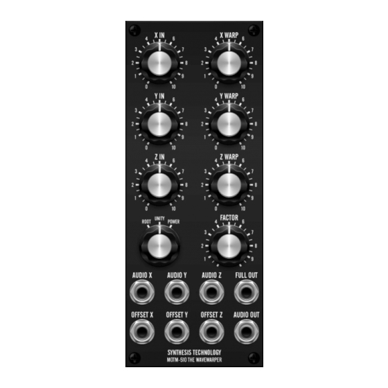
- Page 21 Y IN = 10 Y WARP = 5 Z IN = 0 Z WARP = 7.5 AUDIO OUT POWER = POWER FACTOR = 10 MOTM-440 AUDIO OUT Analog Delay AUDIO OUT Figure 2: Patch Diagram for DEMO #6 SYNTHESIS TECHNOLOGY PAGE 21 MOTM-510 ASSEMBLY 7/11/04 WWW.SYNTHTECH.COM...
-
Page 22: Troubleshooting
The parts are in the right places, you didn’t swap the 1K 1% with a 100K 1%. No solder shorts or missing joints. Again: when the rotary switch is turned or even slightly turned, the module with output spikes (‘pops’) or crackling. This is normal operation. SYNTHESIS TECHNOLOGY PAGE 22 MOTM-510 ASSEMBLY 7/11/04 WWW.SYNTHTECH.COM... -
Page 23: Specifications
Attenuator for IN5 GENERAL Power Supply -15VDC @ 23 ma nominal +15VDC @ 23 ma nominal Size 2U x 5U 3.72” x 8.72” 88.2mm x 221.5mm Depth behind panel 4.375 inches (111mm) SYNTHESIS TECHNOLOGY PAGE 23 MOTM-510 ASSEMBLY 7/11/04 WWW.SYNTHTECH.COM...
Need help?
Do you have a question about the MOTM-510 The WaveWarper and is the answer not in the manual?
Questions and answers