
Summary of Contents for BRUEL & KJAER VIBROCONTROL 8000
- Page 1 Instruction VIBROCONTROL 8000 Machinery Protection System (VC-8000) Operation and Maintenance OPERATION AND MAINTENANCE INSTRUCTION MANUAL Keep it accessible for future reference...
- Page 2 Trademarks and Copyrights All trademarks, service marks, and/or registered trademarks used in this document belong to BK Vibro America Inc., except as noted below: Bently Nevada , Velomitor, REBAM, and Keyphasor are marks of the General Electric Company in the United States and other countries.
- Page 3 Brüel & Kjaer Vibro │ Instruction Content VC-8000 MPS Content VC-8000 Machinery Protection System Rack Chassis Four Basic Cards for the VC-8000 1.2.1 Rack Connection Module (RCM) 1.2.2 System Access Module (eSAM or bSAM) 1.2.3 Universal Monitoring Module (UMM) 1.2.4 Temperature Monitoring Module (TMM) Touch Screen Display Panel 1.3.1...
- Page 4 3.7.2 Clearance and Cooling 3.7.3 3300 or 7200 Replacement 3.7.4 Mounting Orientation 3.7.5 Moving Mounting Brackets in the Field Engineering - Channel Layout Phase Trigger Channels Orbit (XY) Pairs Relay Logic (Group Lines) Engineering – CMS Gateway Engineering - Managing and Minimizing Alarms Set Effective Time Delays Use Non-Latching Alarms, &...
- Page 5 Brüel & Kjaer Vibro │ Instruction Content VC-8000 MPS UMM Sensor Wiring 8.1.1 3-Wire Proximity Transducers 8.1.2 Wiring 3-Wire Accelerometers 8.1.3 Wiring IEPE Transducers 8.1.4 Wiring Moving Coil Velocity Sensors 8.1.5 Wiring Proximity - Speed Sensors 8.1.6 Wiring Magnetic Pickup - Speed Sensors 8.1.7 Wiring Proximity Switch - Speed Sensors 8.1.8...
- Page 6 9.7.4 Set Rack Time with Rack Maintenance Software 9.7.5 Time Synchronization via Modbus Software – Introduction (Start Here) 10.1 Software Installation 10.2 Rack Setup - Software Navigation 10.3 Helpful Tips 10.3.1 Default Units 10.3.2 Copy and Paste 10.3.3 Sort and Multiple Column Sort 10.3.4 Disable Unused (Spare) Channels 10.3.5...
- Page 7 Brüel & Kjaer Vibro │ Instruction Content VC-8000 MPS 12.1.8 Event Lists 12.1.9 Firmware and Hardware Info 12.2 Configuring the VC-8000 Displays 12.2.1 Module Description 12.2.2 Channel Names 12.2.3 Asset level 1 & Asset Level 2 Groups 12.2.4 Channel and Asset Group Order 12.3 Simulating the Display 12.4...
- Page 8 14.1.1 Slot, Type, Description, Notes 14.2 SAM View Configuring - Channels Tab 15.1 Summary View 15.1.1 Channel On/Off, Slot, Channel 15.1.2 Channel Type, Transducer Type 15.1.3 Transducer Direction, Orientation 15.1.4 Associated Phase Trigger 15.1.5 Channel (Tag) Name 15.1.6 Asset Level 1 & Asset Level 2 15.1.7 Alert &...
- Page 9 Brüel & Kjaer Vibro │ Instruction Content VC-8000 MPS 17.3.3 For All (1 and 2 and 3…) Logic Block 17.3.4 For Any XY Pair (2oo2 Enforced) 17.3.5 For Any XY Pair (2oo2) 17.4 Using Channel Input Blocks 17.4.1 Channel Input with ‘Or’ 17.4.2 Channel Input with ‘And’...
- Page 10 21.3.6 Allow Invalid Address 21.3.7 Allow Status Register Writes 21.4 The Standard (or Default) Modbus Map 21.4.1 View (Export) the Modbus Map 21.5 Create a Custom Modbus Map 21.5.1 Reverting Back to the Standard Map 21.6 Modbus Functions 21.6.1 Read Relay Channel Status Registers 21.6.2 Read Channel (or Measurement) Status Registers 21.6.3...
- Page 11 Brüel & Kjaer Vibro │ Instruction Content VC-8000 MPS 23.7.3 Upgrading the SAM (CMS) Firmware 23.8 License Upgrades 23.9 Password Reset 23.10 Hardware Information 23.11 Bypass a Signal (or Relay) Channel 23.11.1 Bypass Signal Channel 23.11.2 Bypass Relay Channel 23.12 Troubleshooting Phase Trigger Channels Complete List of Channel Types 24.1 Standard Channels...
- Page 12 24.7.1 Air Machine Radial Vibration 24.7.2 Radial Vibration with Smax 24.8 Reciprocating Machines 24.8.1 Recip Crankcase Velocity 24.8.2 Recip Cylinder Pressure 24.8.3 Recip Impact 24.8.4 Recip Rod Drop 24.9 Rolling Element Bearing Monitoring 24.9.1 Enveloped Acceleration (Don’t use) 24.9.2 REBAM channel 24.9.3 REB Acceleration 24.9.4...
- Page 13 Brüel & Kjaer Vibro │ Instruction Content VC-8000 MPS Appendices 26.1 Environmental Information 26.2 File Extensions █ © Brüel & Kjaer Vibro ● S1079330.002 / V04 ● Page 13 of 188 Technical alterations reserved!
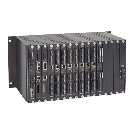
- Page 14 Figure Best Practice VC-8000 Installation 16 position rack, bulkhead mounted to subpanel █ © Brüel & Kjaer Vibro ● S1079330.002 / V04 Page 14 of 188 Technical alterations reserved...
- Page 15 █ © Brüel & Kjaer Vibro ● S1079330.002 / V04 ● Page 15 of 188 Technical alterations reserved!
- Page 16 VC-8000 Machinery Protection System The VIBROCONTROL 8000, or VC-8000 is a versatile API 670, ISO 10816 and ISO 7919 compliant machinery protection system consisting of the following components: · VC-8000 rack, 3 sizes with different mounting options. · Rack Connection Module (RCM) ·...
- Page 17 Brüel & Kjaer Vibro │ Instruction VC-8000 Machinery Protection VC-8000 MPS System Rack Chassis The VC-8000 rack provides flexibility in mounting and arranging monitors modules. The rack is available in three sizes: · • 16 slots, full size rack (19”) ·...
- Page 18 Four Basic Cards for the VC-8000 There are only four basic cards for the VC-8000 Machinery Protection System. · RCM: Rack Connection Module · SAM: System Access Module · UMM: Universal Monitoring Module · TMM: Temperature Monitoring Module Figure 1-2) Four basic cards for the VC-8000 █...
- Page 19 Brüel & Kjaer Vibro │ Instruction VC-8000 Machinery Protection VC-8000 MPS System 1.2.1 Rack Connection Module (RCM) The Rack Connection Module (RCM) installs in slot 1 and provides rack power connections and other rack level interfaces. · Primary power input ·...
- Page 20 1.2.2 System Access Module (eSAM or bSAM) The System Access Module (SAM) installs in slot 2 of the rack, it provides data to external systems and simplifies configuration of the rack. There are two versions of the SAM; The basic SAM (bSAM) and the enhanced SAM (eSAM).
- Page 21 Brüel & Kjaer Vibro │ Instruction Content VC-8000 MPS 1.2.3 Universal Monitoring Module (UMM) · To view orbits in CMS, XY Radial The UMM is configurable for nearly 50 Vibration channels must be paired different channel types for monitoring rotating and reciprocating machinery; this (channels 1&2 or 3&4).
- Page 22 1.2.4 Temperature Monitoring Module (TMM) The TMM module supports 6-channels of thermocouple, RTD, and/or Process Variable inputs. The TMM conditions the transducer signals, including filtering and noise rejection. Each channel input is independently configurable allowing you to mix thermocouples, RTDs, and Process Variable channels.
- Page 23 Brüel & Kjaer Vibro │ Instruction Content VC-8000 MPS Touch Screen Display Panel The VC-8000 rack has an (optional) color touchscreen display module mounted on the rack or remotely up to 10 ft. (3 m) away (like a cabinet door). The display module shows: ·...
- Page 24 Safety Information This manual is a part of the product. Read the manual carefully before using the product and keep it accessible for future use. Intended use The VC-8000 is a rack-based continuous machinery monitoring platform designed to fully comply with American Petroleum Institute Standard 670 for machinery protection systems.
- Page 25 Brüel & Kjaer Vibro │ Instruction Content VC-8000 MPS User Qualification Transport, storage, installation, assembly, connection, commissioning, maintenance and service must be undertaken by qualified technicians (for ATEX systems according to EN 60079-14). The following must be observed: · The instructions in this manual ·...
- Page 26 Related Documents 2.6.1 Instruction Manuals The following manuals contain instructions for specific machines and/or applications. These manuals can be found at the B&K Vibro website. Number Title Document VC-8000 Operation & Maintenance Manual (this document). S1079330 Reciprocating Machines Applications Manual S1342998 Rolling Element Bearing Applications Manual S00002001...
- Page 27 Brüel & Kjaer Vibro │ Instruction Content VC-8000 MPS Engineering - Choosing a Mounting Method The VC-8000 rack’s flexible design allows the monitoring modules to be installed facing forward (wiring in the front of the cabinet) or facing backward (wiring in the rear of the cabinet). This can be helpful, but also confusing if the correct option is not ordered.
- Page 28 Bulkhead Mounting Bulkhead mounting takes full advantage of the VC-8000 rack design. The rack is compact and light. All modules are easily accessible. The bulkhead mount rack, has flush mount brackets installed on the backside of the rack as shown. The mounting-hole pattern for bulkhead mounting is the same as for panel mounting.
- Page 29 Brüel & Kjaer Vibro │ Instruction Content VC-8000 MPS Panel Mounting The panel mounted option is required when mounting the system in an existing cut-out. Bulkhead mounting is preferred if there are not cut-outs. Normally, mounting brackets will be placed so that wiring is from the rear of the cabinet.
- Page 30 19” EIA Rack Mounting (rare) This method is possible, but rare because most 19” EIA cabinets mount the equipment to the very front of the cabinet (see below); this does not leave any room for wiring or wiring harnesses. Recessed brackets can be ordered which push the rack several inches into the cabinet, but it is much better to bulkhead mount the rack onto a subpanel in the cabinet rather than mounting to the rails.
- Page 31 Brüel & Kjaer Vibro │ Instruction Content VC-8000 MPS Mounting Hole Drawings For mounting hole drawings please visit the downloads page on the B&K Vibro website. Other Considerations 3.7.1 Mounting the Display Remotely You can mount the touch screen display (like on a door) up to 10 feet (3.0 m) from the rack.
- Page 32 3.7.3 3300 or 7200 Replacement The 16 slot VC-8000 rack is the same size as the Bently Nevada 7200 and 3300 series 8 Position rack. VC-8000 Racks will mount in the existing panel cut-outs without modification. When replacing a larger BN 3300 or 2700 rack (10P, 12P, and 14P).
- Page 33 Brüel & Kjaer Vibro │ Instruction Content VC-8000 MPS Engineering - Channel Layout There are certain rules that you should be aware of when planning the channel layout in the VC-8000 rack. These are explained below. Phase Trigger Channels The VC-8000 rack allows for six Phase Trigger channels maximum (16P rack). Phase Trigger channels can only be selected in channel 4 of a UMM installed in slots 4-9.
- Page 34 Relay Logic (Group Lines) Although rare, complicated relay logic may exceed the allowable limit for “cross monitor voting”. Cross monitor voting occurs when the logic for the relay channel (i.e. in slot 6) includes signals (i.e. from Slots 4 and 5), as shown in the example below. The VC-8000 architecture provides 16 “group lines”...
- Page 35 Brüel & Kjaer Vibro │ Instruction Content VC-8000 MPS Engineering – CMS Gateway The VC-8000 is perfectly designed to replace existing machinery protection racks (for example BN 3300 or 3500). However, in some cases this is not practical and the VC-8000 will be installed as a gateway for CMS data only.
- Page 36 Engineering - Managing and Minimizing Alarms The VC-8000 rack has several features to help you manage alarms. Those familiar with plant control rooms know that many of the alarms are initially questioned (i.e. Is it real?). Faulty wire connections, faulty sensors, and faulty equipment often make false alarms more common than real alarms. The following features (and recommendations) may help to improve the reliability of the alarms coming from the VC-8000 system.
- Page 37 Brüel & Kjaer Vibro │ Instruction Content VC-8000 MPS Use Rack Inhibit for Light Maintenance Activities Rack Inhibit prevents all signal channels from going into alarm. This is very useful when you are doing light troubleshooting at the rack. Rack inhibit is very helpful and is easy to use. It is strongly recommended. The nice thing about Rack Inhibit (when compared to Bypass) is that it does not “turn off”...
- Page 38 Trip Multiply Trip Multiply was designed for large machines that pass through critical speeds (resonance) on start- up. It allows “protection” to remain in place but the alarms are temporarily raised to a higher value (i.e. 9 mils instead of 3 mils). In practice, the startup of large critical machines is so closely monitored by plant personnel that Trip Multiply is rarely used.
- Page 39 Brüel & Kjaer Vibro │ Instruction Content VC-8000 MPS 6.9.3 Can I Bypass “the Rack” to Avoid a False Trip? No. No. You cannot bypass “the rack”. The bypass function is often misunderstood. Most of the time the phrase “bypass the rack” means “isolate the rack from external systems”. The rack bypass function is a “self-governing”...
- Page 40 Wiring - Power and Grounding RCM Power Strategy Redundancy The (single) RCM accepts two external and independent supplies. The RCM routes the +24 Vdc (from each supply) to the backplane. Each module (UMM, TMM, and SAM) selects the highest in-specification voltage line. As soon as one voltage is removed or drops below the other, all modules seamlessly switch to the alternate source, assuring uninterrupted operation.
- Page 41 Brüel & Kjaer Vibro │ Instruction Content VC-8000 MPS 7.2.2 Input Power Fuse Protection The RCM includes power input fuse protection and reverse wiring protection. The fuse is not replaceable. All other power supply voltages and conditioning circuits are distributed on the SAM and monitoring modules.
- Page 42 7.2.5 Using Plant-Wide +24 Vdc Power Occasionally a site will have a main +24 Vdc line that is used by all +24 Vdc devices. In this case a 24 Vdc isolator would be required for the VC-8000 rack. The isolator is needed because the VC-8000 rack power common is the same as the UMM common; and connecting the plant-wide +24 Vdc to the RCM may cause a ground fault.
- Page 43 Brüel & Kjaer Vibro │ Instruction Content VC-8000 MPS Connecting Grounds 7.3.1 System Chassis Ground Connect the chassis ground wire to the chassis terminal at the RCM. Follow electrical codes when selecting wire size, maximum wire length, and maximum earth ground resistance.
- Page 44 Wiring – Sensors UMM Sensor Wiring This section describes wiring for the following sensor to the UMM: · -24 V, 3-wire Proximity Transducers · -24 V, 3-wire Acceleration Transducers · +24 V, 2-wire IEPE Accelerometers · +24 V, 2-wire IEPE Velocity Sensors ·...
- Page 45 Brüel & Kjaer Vibro │ Instruction Content VC-8000 MPS 8.1.3 Wiring IEPE Transducers The UMM provides +24 Vdc at 3 mA constant current to power typical IEPE 2-wire sensors. Connect the transducer “A” wire to the UMM Sig/A wire and the transducer “B” wire to the UMM COM/B terminal as shown in below: Figure 8-3) IEPE Transducer Wiring IMPORTANT...
- Page 46 8.1.5 Wiring Proximity - Speed Sensors Wire speed sensors as shown. Although Tachometers can be installed on any UMM channel, Phase Trigger channels are limited to Channel 4 (slots 4-9) only. Power supplied is -24 Vdc. Figure 8-5) Moving Coil Velocity Sensor Wiring 8.1.6 Wiring Magnetic Pickup - Speed Sensors The UMM can also accept Magnetic Speed Pickups.
- Page 47 Brüel & Kjaer Vibro │ Instruction Content VC-8000 MPS 8.1.8 Wiring Two-wire (4-20 mA) Loop-Powered Transmitters Connect 4 to 20 mA 2-wire, loop-powered transmitters, as shown below. The UMM provides power (-24 Vdc) sufficient to power the transmitter. Inside the UMM the 4 to 20 mA current signal passes through a 249-ohm sense resistor to create a -1.0 V to -5.0 V analog signal.
- Page 48 8.1.9 Wiring Externally Powered (4-20 mA) Transmitters You can use externally powered transmitters. This includes 4 to 20 mA, 0 to 5 Volts, 1 to 5 Volts, and 0 to -10 Volts. Connect as shown in Figure 8-9 with the transmitter loop (+) connected to SIG and loop (-) connected to COM.
- Page 49 Brüel & Kjaer Vibro │ Instruction Content VC-8000 MPS TMM Sensor Wiring The TMM can accept any combination of 2, 3, and 4-wire RTDs or thermocouples. 8.2.1 Wiring RTDs Figure 8-10) RTD Wiring Shield White Shield 2-wire White Shield 3-wire White White Shield...
- Page 50 8.2.2 Wiring Thermocouples Wire thermocouples as shown. The VC-8000 isolates thermocouple common lines; this allows connection to grounded tip thermocouples. All thermocouple inputs share the same common plane, so grounded tip thermocouples should be at the same ground potential. Figure 8-11) Thermocouple wiring ANSI/ASTM E-230 Color Coding IEC 584-3 Color Coding Type...
- Page 51 Brüel & Kjaer Vibro │ Instruction Content VC-8000 MPS 8.2.3 TMM and Externally Powered (4-20 mA) Transmitters (Use Caution) The TMM can be used with 4 to 20 mA transmitters (externally powered) using a 68-ohm resistor. The resistor converts the current into a voltage range suitable for TMM measurements. Use Caution.
- Page 52 Figure 8-13) TMM process variable terminal block 8.2.4 Connecting Voltage Mode (< 1.5V) Transmitters Voltage mode transmitters, with an output voltage range of less than 1.5 volts, can connect directly to the TMM. Wire the positive output to the TMM channel B terminal and the negative output to the TMM channel C terminal.
- Page 53 Brüel & Kjaer Vibro │ Instruction Content VC-8000 MPS Wiring - Interfacing to External Systems (DCS) There are many features in the VC-8000 hardware designed specifically to interface to the DCS or other external systems. Some are for sharing information, others allow a measure of control. This section provides some guidelines on how best to use these interfaces.
- Page 54 9.1.1 Modbus/TCP Ethernet Port (Also NTP) The DCS NET port on the SAM is for Modbus/TCP. This port is an Ethernet port (10/100baseT, using a standard CAT5 or CAT6 cable with an RJ45 connector). Normally there is only one Modbus client reading data from the rack; but (when needed) Modbus TCP does support multiple clients.
- Page 55 Brüel & Kjaer Vibro │ Instruction Content VC-8000 MPS 9.1.2 Modbus Serial Port (RS-232, RS-422/485) The SAM provides a single RJ45 connector for Modbus serial communication. The RJ-45 port is used for convenience; this connector is not a network port. The serial port can used to connect to RS-232, RS-422 (4-wire), RS-485 (4-wire), and RS-485 (2-wire) Modbus clients.
- Page 56 9.1.2.1 RS-422 (4-Wire) Daisy Chain The VC-8000 rack does not support RS-422 daisy chain. If the DCS (Modbus Client) is an RS-422 port, we recommend two viable options. · Use a Modbus Serial (RS-422) to Modbus TCP converter and configure the VC-8000 racks for Modbus TCP.
- Page 57 Brüel & Kjaer Vibro │ Instruction Content VC-8000 MPS Fault (Not OK) Relay The Fault (Not OK) Relay activates whenever machine protection is compromised due to a detected VC-8000 or instrumentation failure such as a sensor going bad (Not OK). When the DCS is connected to the Fault (Not OK) Relay, plant operators can be notified that there is a problem with the machinery protection system.
- Page 58 9.2.1 Wiring to the Fault (Not OK) Relay The Fault relay is ‘Normally Energized’. The relay is labelled NC for Normally Closed, ARM for Armature, and NO for Normally Opened. These labels indicate the position of the armature when there is no power applied to the rack (i.e. ARM will be connected to NC.). The Fault (Not OK) relay is a single-pole, double-throw (form C) relay.
- Page 59 Brüel & Kjaer Vibro │ Instruction Content VC-8000 MPS Rack Control Signals (Reset, Inhibit, Trip Multiply, SAI, Bypass) There are six input commands (controls) available on the VC-8000. These functions are described in the table below. Command Description Resets all latched alarms. This control is highly recommended Reset (RST) when using latched alarms in the MPS.
- Page 60 9.3.1 RCM Discrete Input Connector There are four discrete control input signals on the RCM: Rack Reset (RST), Rack Inhibit (INH), Rack Trip Multiply (TM), and Rack Special Alarm Inhibit (SAI). These four controls operate at the rack level. For example, if the Inhibit contact is closed, all signal channels in the rack will be inhibited.
- Page 61 Brüel & Kjaer Vibro │ Instruction Content VC-8000 MPS 9.3.3 Modbus Discrete Input Commands Modbus commands can be used to set the Reset, Inhibit, Trip Multiply, or SAI commands at the rack level only; for example, you cannot use Modbus commands to place a “Machine Group”...
- Page 62 Buffered Output Connectors 9.4.1 UMM Buffered Output Connector (RJ-45) Each UMM has an RJ-45 connector that provides access to buffered output signals in the UMM. These can serve for temporary or permanent connections. Breakout cable 100431-AA is used to connect the UMM to the back of a patch panel. Users can then connect multi-meters (or other devices) to the front of the patch panel.
- Page 63 Brüel & Kjaer Vibro │ Instruction Content VC-8000 MPS 9.4.2 RCM (Secondary) Buffered Output Connector The RCM buffered output connector provide secondary access to buffered analog signals from all UMM modules. This connector is rarely used and is limited to just 10 ft. (3 m) maximum.
- Page 64 9.5.1 4-20 mA Fault Conditions In the event of a sensor fault, the 4 to 20 mA output will drop to bottom scale (4 mA). This value is configurable in the MPS Setup software. A 2 mA clamp option is also available for faulted channels. An output between 20 mA and 24 mA indicates an over-range condition.
- Page 65 Brüel & Kjaer Vibro │ Instruction Content VC-8000 MPS Relay Output Relay outputs from the VC-8000 can be used to drive annunciators (lights, horns), to drive a machine trip circuit, or to connect to a DCS etc. The DCS might use the input for a status indicator on an operator screen (HMI) or to drive a secondary relay.
- Page 66 DANGER! Higher contact potentials cause current levels which are extremely dangerous and can lead to injury or even death! The permissible levels of contact potentials are: · Max. 50 Volts in the case of AC voltages. UMM and TMM relay connectors support wire gauges from 16 to 28 AWG. When using ferrules, the maximum wire size is 1 mm (17 AWG).
- Page 67 Brüel & Kjaer Vibro │ Instruction Content VC-8000 MPS 9.7.3 Time Synchronization via NTP (via SAM DCS port) The VC-8000 rack can synchronize its time with a master clock using an NTP server. This connection uses the DCS NET (Modbus TCP) port. To use an NTP server, change the Time Source setting to “NTP (via DCS Port)”.
- Page 68 9.7.5 Time Synchronization via Modbus The rack time can also be sent using a Modbus command. The Modbus timestamp value is an epoch timestamp and is the number of “tics” that have elapsed since January 1, 1970 at midnight. In the VC- 8000 one “tic”...
- Page 69 Brüel & Kjaer Vibro │ Instruction Content VC-8000 MPS Software – Introduction (Start Here) 10.1 Software Installation Download the latest software from the Brüel & Kjær Vibro website. You must have Administrator privileges on your computer to install the software. To install the software: ·...
- Page 70 10.2 Rack Setup - Software Navigation The Rack Setup software is a spreadsheet type application. The configuration parameters are viewed in rows and columns. Copying and pasting between cells, sorting columns, and filtering are available. There are five main areas used for navigation and setting properties. Figure 10-1) Software Navigation Features Control Description...
- Page 71 Brüel & Kjaer Vibro │ Instruction Content VC-8000 MPS 10.3 Helpful Tips 10.3.1 Default Units Before you start adding modules - set the default units (imperial or metric) from the File menu. New modules and channels will default to these units.
- Page 72 10.3.3 Sort and Multiple Column Sort You can sort a single column. Click the mouse on the column header to sort by that column. Click on the column label again to change the order of the sort. You can sort multiple columns. Sort the first column by clicking the mouse on the column header.
- Page 73 Brüel & Kjaer Vibro │ Instruction Content VC-8000 MPS 10.3.6 Grid Filter Use the filter to show only the rows you are interested in seeing. The filter is not case sensitive and applies to all column headers (marked with an asterisk) simultaneously. When the filter is active the filter control has a bold border.
- Page 74 10.3.7 Hard to Find (Hidden) Properties A few channels and measurements have configuration properties that are not shown in the spreadsheet view. These properties can only be found in the properties panel. An example is the Ramp Angle for a Differential Expansion channel. If you are not familiar with the channel type you are configuring, you will need to check the properties pane to ensure that all settings have been configured.
- Page 75 Brüel & Kjaer Vibro │ Instruction Content VC-8000 MPS 10.4 Basic Rack Configuration Follow these basic steps when starting a new configuration: 1. Start MPS Setup Software 2. Set your default units (File, Default Units). 3. Select File, New. 4. Select the Modules Tab. Figure 10-10) Select Module Type 5.
- Page 76 Software – Connecting to the Rack You can connect to the rack locally over a USB connection, or remotely over an ethernet connection. For security reasons, the remote connection requires a software license and local (USB) setup before it will work. Local connection requires a USB cable and (of course) access to the rack. 11.1 Local Connection (Mini-B USB port) The MPS software connects to the rack over a USB connection.
- Page 77 Brüel & Kjaer Vibro │ Instruction Content VC-8000 MPS 11.2 Remote Connection (Ethernet) Remote (Ethernet) connection to the rack uses the CMS ethernet port, and the CMS IP address. The remote connection feature must be licensed, configured, and enabled (see section 11.6). To connect remotely: ·...
- Page 78 11.3 Get the Configuration from the Rack Use the MPS Setup software to Get and view the current rack configuration. · Open MPS Setup Software · Wait for the software to connect · Select ‘Get’ · The current configuration will be uploaded Figure 11-3 Get and Prepare to Send 11.4 Send the Configuration to the Rack...
- Page 79 Brüel & Kjaer Vibro │ Instruction Content VC-8000 MPS Authority User Authority User Connect Save a VC-8000 Maintenance file View display screens, event lists, etc. Acknowledge alarms Bypass signal channels or relays X (PW) Update Firmware X (PW) Upgrade Licenses Password reset file (forgot password) Set rack time Request a set of Boost mode waveforms...
- Page 80 11.6.1 Verify Your Remote MPS License Remote connection requires a software license. To see if you have the appropriate license: · Connect to the rack with MPS Maintenance software. · Select the Hardware Info tab and view the ‘supported features’ column for Slot 2 (SAM). ·...
- Page 81 Brüel & Kjaer Vibro │ Instruction Content VC-8000 MPS 11.6.3.1 Setting Legacy Passwords (SAM Firmware 5.2 and older) To set the password: · Open Properties pane for SAM configuration. · Select to show the Legacy Passwords. · Enter the password in the Password and Confirm Figure 11-7) Set Rack Passwords Password cells.
- Page 82 Software - Visualizing VC-8000 Data VC-8000 data is typically visualized as follows: · VC-8000 local display on touch screen panel (optional) · VC-8000 Maintenance software (laptop computer) · Multimeter connected at the rack. · DCS screens (via Modbus, or Analog 4-20 mA) ·...
- Page 83 Brüel & Kjaer Vibro │ Instruction Content VC-8000 MPS 12.1.1 Rack View Connect MPS Maintenance software to see the Rack view. Rack view shows the status of specific functions of the RCM and SAM (on the left panel). It also shows bar graph values and icons for each relay channel status.
- Page 84 RCM and SAM functions and their respective indicators on the Rack View display are described in the table below. Indicator Color Description Green OK relay normal (all channels are in OK) Gray OK relay tripped (channel(s) in a fault condition) Green Trip Multiply Active Multiply...
- Page 85 Brüel & Kjaer Vibro │ Instruction Content VC-8000 MPS 12.1.2 Percent-to-Danger (Red) Line The Percent-to-danger line represents the danger alarm. However, it does not represent a real number, such as 4 mils (100 µm); Instead it represents how close a channel is to entering danger (percentage).
- Page 86 12.1.4 Full Signal Channel View Select More (channel detail view) to see the Full Channel view. Figure 12-2) Full Signal Channel View 12.1.5 Relay Channel View Select any relay channel to see the relay channel view. Notice that all four relay channels are shown on the screen, but only one channel is the “selected”...
- Page 87 Brüel & Kjaer Vibro │ Instruction Content VC-8000 MPS 12.1.6 Machine View The Machine view shows the data organized by Asset Level 1 and Asset Level 2 groups. In the example shown below (Figure 12-4) “101 Steam Turbine” is an Asset Level 1 group. “Turb Speed”...
- Page 88 12.1.8 Event Lists View the event lists (Alarm or System) by selecting the appropriate tab. The event lists can be sorted by clicking on the column header. A laptop running Maintenance software should be used to view the event lists. The event list can be multi-sorted by holding the SHIFT key while clicking the second column header etc.
- Page 89 Brüel & Kjaer Vibro │ Instruction Content VC-8000 MPS 12.2.1 Module Description The module descriptions will be shown in the Maintenance display on the Rack tab of the Maintenance display. The SAM description should be 8 characters or less. The UMM/TMM description can be 18 characters.
- Page 90 12.2.3 Asset level 1 & Asset Level 2 Groups Asset 1 and Asset 2 are used to help organize, identify, and group channels. Asset names have multiple uses in the VC-8000 system. · Asset names are used to organize the Machine view display (see 12.2.3.1).
- Page 91 Brüel & Kjaer Vibro │ Instruction Content VC-8000 MPS 12.2.3.1 Asset Group Example (Large Machine) Table 12-4 shows a typical arrangement for a rack with only one machine. Asset Level 1 is the machine case. Asset Level 2 is the sensor location or measurement name. Name Asset Level 1 Asset Level 2...
- Page 92 12.2.4 Channel and Asset Group Order Asset Level 1 Order, Asset Level 2 Order, and Channel Display Order are used to manage the Machine View display. It is best to complete your configuration before setting the order of your channels, and Assets. Figure12-10) Channel and Asset Display Order Table 12-6 shows how the Assets and channels are ordered.
- Page 93 Brüel & Kjaer Vibro │ Instruction Content VC-8000 MPS 12.3 Simulating the Display You can easily simulate the front panel display (on your laptop) to verify your display configuration. Step Screen Capture Complete your configuration. Open the File menu and select Save as Simulator File. Close all other MPS programs.
- Page 94 12.4 Troubleshooting the Display Panel 12.4.1 Display Cursor Visible In the SAM configuration there is a setting called Display Cursor Visible. When checked, this option places a very small dot (one pixel) on the touch screen showing the current cursor position. The cursor is most often used when troubleshooting touch screen issues.
- Page 95 Brüel & Kjaer Vibro │ Instruction Content VC-8000 MPS 12.5 Connecting a Digital Multimeter 12.5.1 Touch Screen Display Buffered Output Connectors (BNC) Each touch screen display has 3 BNC connectors that provide selectable access to any of the channels in the rack. Step 1 Step 2 Step 3...
- Page 96 Configuring - CMS Data Collection 13.1 Data Types The SETPOINT CMS system collects a full suite of data types to increase your ability to diagnose machinery problems (see Table 13-1). Data Type Examples Radial Vibration (Direct) Gap, Axial (Direct), Seismic (Direct) Static 1X Amplitude, 1X Phase Vector Data...
- Page 97 Brüel & Kjaer Vibro │ Instruction Content VC-8000 MPS The SAM (CMS) firmware must be version 3.0 or higher as shown in the table below. CMS Function CMS (SAM) Firmware Revision Required 3.0 or higher CMS PI 4.02 or higher CMS SD 5.0 or higher CMS HD...
- Page 98 If you are using an OSI Soft PI System, the CMS Navigation Path is imported into the PI Asset Framework (AF) database. After the initial instance is created, the user can modify the AF database (using OSI Soft PI tools) if needed. 13.2.4 Synchronous Waveforms Synchronous Waveform data collection is configured in terms of the number of samples collected per shaft revolution, evenly spaced in phase.
- Page 99 Brüel & Kjaer Vibro │ Instruction Content VC-8000 MPS 13.3 Waveform Data Collection Triggers Each UMM channel is in an infinite loop of continuously sampling waveforms. The “triggers” described in this section are used by the UMM channel to determine when the sample is to be saved. If the sample is to be saved, the UMM channel stores the waveform until it is polled (queried) for the waveform.
- Page 100 13.3.3 I-Factor % (Dynamic Collection Rate (% Change)) The VC-8000 monitor will save a waveform whenever there is a significant change in vibration. The patented I-Factor % allows you to tell the VC-8000 what you consider to be a “significant” or “interesting”...
- Page 101 Brüel & Kjaer Vibro │ Instruction Content VC-8000 MPS 13.3.5 Boost Mode In Boost Mode the rack suspends Delta RPM and I-Factor waveform collection, and begins saving all waveforms continuously. It is ideally suited for electric motor start-ups which are measured in seconds rather than minutes. Boost mode channels require five settings (Boost Mode enabled, Phase Trigger association, Delta RPM, High Trigger (RPM), Low Trigger (RPM))
- Page 102 13.3.6 Paired Channels (XY) Paired channels will always collect waveforms together. There is no setting in the MPS software for “pairing’ channels together – it happens automatically. For example: If Brg 1X and Brg 1Y are paired, and Brg 1X has a waveform collection triggered (I- Factor), Brg1Y will also have a waveform collection triggered and the waveforms will have the same time stamps.
- Page 103 Brüel & Kjaer Vibro │ Instruction Content VC-8000 MPS 13.4.1 Low Trigger (RPM), High Trigger (RPM) – Static Data Collection The Low to High Trigger setting defines the machine transient window. This window is used to control Exception Deviation, PI Compression, and Boost Mode. Feature Description Defines when higher density static data is saved (by the Adapter) during...
- Page 104 13.4.1.2 Compression Deviation (PI Only) The OSI Soft PI Data Archive uses a “swinging door” algorithm to compress time-series data. The algorithm stores only what is needed to provide an accurate data history. The sensitivity of the algorithm is controlled by the Compression Deviation setting. Compression Deviation should be set at twice the Exception Deviation value.
- Page 105 Brüel & Kjaer Vibro │ Instruction Content VC-8000 MPS 13.5 CMS-SD, and CMS-HD 13.5.1 Excellent “Flight Recorder” Solution The most common usage of CMS-SD (HD) is for post-event analysis (flight recorder data). CMS-SD/HD is a powerful flight recorder solution. Data is recorded inside the rack; network issues, server issues etc.
- Page 106 13.5.3 CMS-HD (Internal Solid Sate Drive) CMS-HD uses an internal solid-state drive (SSD) to store CMS data. Users connect directly to the VC-8000 ethernet port to view CMS-HD data. IMPORTANT The CMS ethernet port should not be placed on a public data network (i.e. remote users). For remote connectivity, use CMS-XC or CMS-PI.
- Page 107 Brüel & Kjaer Vibro │ Instruction Content VC-8000 MPS Configuring - Modules Tab Use the Modules tab to add, or remove monitors. 14.1 All View The Modules tab only has two views; All and SAM. Normally you will use the ‘All’ view. 14.1.1 Slot, Type, Description, Notes Slot: The position of the monitor in the rack.
- Page 108 Configuring - Channels Tab Use the channels tab to set the channel and transducer properties. Begin with the Summary view. Then progress to the other Channel Views; such as Customize Transducer view, or the Phase Trigger view. 15.1 Summary View Figure 15-1) Channels Tab The Summary view shows common channel settings as described in the following sections.
- Page 109 Brüel & Kjaer Vibro │ Instruction Content VC-8000 MPS 15.1.6 Asset Level 1 & Asset Level 2 Asset Level 1 and Asset Level 2 are used in conjunction with the tag name, to identify the machine train, machine case, and location of the sensor. Asset Level 1 and Asset Level 2 are also used as major (level 1) and minor (level 2) groupings.
- Page 110 15.2.3 Max OK & Min OK (Fault Limits) The setting specifies the fault values for the selected transducer. When the transducer signal is outside the OK limits the channel is faulted (Not OK) and channel data is marked invalid. When you select a transducer, these values are set to recommended values. 15.2.4 Transducer Power Specifies the power to be provided to the sensor.
- Page 111 Brüel & Kjaer Vibro │ Instruction Content VC-8000 MPS Configuring - Measurements Tab Modify alarms and full-scale range settings from the Measurements tab. Use the Primary view selection to simplify the layout (this will hide all 1X, 2X, and Gap measurements). Figure 16-1) Measurements Tab 16.1 Primary and All –...
- Page 112 16.1.3 Alert Alarm Type, Alert Alarms The Alert Type options are shown below. Alert Type Available Set Points Operation None The Alert set point is disabled. Disabled Alert Alarms when the input is greater than Over the Alert set point. Under Alert Alarms when the input is less than Under...
- Page 113 Brüel & Kjaer Vibro │ Instruction Content VC-8000 MPS 16.1.6 High Pass, Low Pass Corner Frequency Measurements that show a high pass, and low pass filter, apply a pre-filter first, and then determine the measurements indicated. This pre-filter is applied to these static measurements only –...
- Page 114 16.1.8 X (Tracking Filter) The X column sets the tracking filter for the measurement (when applicable). Tracking filters can be set from 0.01 to 15.99. A radial vibration measurement has two standard tracking filter measurements (1X, and 2X). A tracking filter includes both an amplitude and a phase measurement. To change (for example) the existing 2X tracking filter to 0.5X, simply edit the X field (from 2 to 0.5).
- Page 115 Brüel & Kjaer Vibro │ Instruction Content VC-8000 MPS 16.1.10 Adding Measurements or Waveforms to a Channel Many channel types allow you to add measurements. For example, you may want to measure both integrated and non-integrated data from an acceleration sensor or add an additional tracking filter to a Radial Vibration channel.
- Page 116 16.2 Vector (nX) View This nX view displays all vector measurements and displays the Revs Per Vector parameter. The Revs Per Vector parameter allows you to tune vector calculations for fast response (20 Revs Per Vector) or high differentiation (100 Revs Per Vector). The default value is 20 shaft revolutions per vector calculation;...
- Page 117 Brüel & Kjaer Vibro │ Instruction Content VC-8000 MPS Configuring - Relays Tab 17.1 Basic Navigation and Layout The Relay Logic tab allows you to diagram your logic. The basic elements are shown below. Figure 16-1 Relays tab Control Description (1) Add button Add logic blocks as needed (2) View...
- Page 118 17.2 Relay Channel (and Relay Settings) Follow these steps to configure the relay operation (see Figure 17-3): 1. To enable a relay, check the box labeled On. To disable the relay, uncheck the box. 2. Notice the channel number (1 through 4). Figure 17-3) Relay channel settings 3.
- Page 119 Brüel & Kjaer Vibro │ Instruction Content VC-8000 MPS 17.3 Using Pre-Programmed Logic Blocks Pre-programmed logic blocks make relay configuration robust and simple. The ‘For Any (1 or 2 or 3…)’ logic block is shown in the table below. Control Selection Description Selected group (Asset Level 1 or 2)
- Page 120 17.3.2 For Any (1 or 2 or 3…) Logic Block The ‘For Any (1 or 2 or 3…)’ logic block performs the logical OR function. All channels in the selected asset group (“With: The Rack”, or “With: Motor A”) are included in this logic. This block is often used for annunciation of any Alert alarm on the machine.
- Page 121 Brüel & Kjaer Vibro │ Instruction Content VC-8000 MPS 17.3.3 For All (1 and 2 and 3…) Logic Block The "For All" block performs the logical AND function. All channels in the selected asset group (“With: The Rack”, or “With: Motor A”) are included in this logic. Channel Status (All) Alert/Danger Fault...
- Page 122 17.3.4 For Any XY Pair (2oo2 Enforced) In this block, channels X and Y must be UMM channels 1,2 (or 3,4) and have the same channel type. This is called a channel pair. All paired channels in the selected asset group (“With: The Rack”, or “With: Motor A”) are included in this logic.
- Page 123 Brüel & Kjaer Vibro │ Instruction Content VC-8000 MPS 17.3.5 For Any XY Pair (2oo2) The ‘For Any XY Pair (2oo2)’ block performs the logical AND functions across the two channels in an XY pair and then the logical OR function across all pairs in the group. Channels X and Y must be UMM channels 1,2 (or 3,4) and have the same channel type.
- Page 124 17.4 Using Channel Input Blocks 17.4.1 Channel Input with ‘Or’ Channel Input blocks (Figure 17-10) allow you to select the channel, measurement, and alarm status to apply to Boolean logic. To connect the blocks, select the black square and drag the mouse over to the input socket on the next block.
- Page 125 Brüel & Kjaer Vibro │ Instruction Content VC-8000 MPS 17.4.2 Channel Input with ‘And’ Below are examples of the Channel Input block combined with ‘And’ logic (Figure 17-11). Figure 17-11) Channel Input block (And logic) Table 17-12 shows an example that requires two channels to be in Alert before the relay will trip. This scenario minimizes false trips, but may increase missed trips.
- Page 126 17.4.3 Deleting a Block To delete a block, select the block and select delete on your keyboard. To delete a connector, select the connector at the input to the block and select delete on your keyboard. Figure 17-12) Delete connector 17.4.4 Configuring DPDT Pairs Sometimes it is necessary to trip two relays instead of one.
- Page 127 Brüel & Kjaer Vibro │ Instruction Content VC-8000 MPS Configuring - Analog Outputs Tab Use the settings on the Analog Output tab to specify which measurements (from that module) will be sent to the 4-20 mA connector on the UMM (or TMM). Any measurement (Gap, or 1X) can be assigned as the output to the analog output channel.
- Page 128 Configuring - Asset Display Order Tab The order of channels and groups is set in two locations. The order of groups is set from the Asset Display Order tab (see figure below). The order of channels (within groups) is set from the Channels tab (Summary view). See more on setting Asset (group) names in section 12.2.3.1.
- Page 129 Brüel & Kjaer Vibro │ Instruction Content VC-8000 MPS Configuring – Examples This section contains examples of commonly used channel types, and how they can be configured. 20.1 Acceleration Use the Channels tab and the Summary view to configure channels. Select the Channel Type and then select the Transducer.
- Page 130 20.2.2 Upscale (Normal) Direction The setting “Upscale Direction” specifies the normal (or expected) thrust direction (5). In Error! Reference source not found. the setting would be Upscale Direction = “Away from probe”. Axial shaft movement is predictable. Machine pressures and/or processes continuously push the shaft the normal (or expected) direction (5).
- Page 131 Brüel & Kjaer Vibro │ Instruction Content VC-8000 MPS The maximum signal frequency that can be detected is 180,000 Hz. For example, If the machine speed is 3,600 rpm and the event ratio is 40, the expected signal frequency (at running speed) will be 144,000 Hz.
- Page 132 20.4 Process Variable Channels Use this view to configure process variable measurements. For process variable channels the top scale, bottom scale, and units are set in two locations. · First, set the scaling in the Process Variable view Figure 20-5) Process Variable Channels (Channels tab).
- Page 133 Brüel & Kjaer Vibro │ Instruction Content VC-8000 MPS 20.6 Temperature Channels Use this view to configure temperature channels. 20.6.1 Transducer Power Select whether the connected sensor is a Thermocouple, Figure 20-7) Temperature Channels RTD (2, 3, or 4 wire) or Process Variable transmitter. The TMM will switch the inputs according to the transducer power to provide the correct sensor excitation.
- Page 134 Configuring – Modbus The SAM module has two ports for Modbus communication. The most commonly used port is the Modbus TCP (Ethernet). The SAM also provides a serial Modbus RTU port. The Modbus Serial port uses the RJ-45 jack for convenience only.
- Page 135 Brüel & Kjaer Vibro │ Instruction Content VC-8000 MPS 21.3.2 Scaled Value Scaled Value sets the full-scale data range for Modbus data. Scaled Value Bits Application Compatibility with BN 3300 (i.e. 0-4095 is 0-10 mils) 4095 16-bit DCS systems (i.e. 0-65535 is 0-10 mils) 65535 21.3.3 Modbus Map (Standard or Custom) This value indicates whether the SAM is using the standard (or default) Modbus map, or a custom...
- Page 136 21.4 The Standard (or Default) Modbus Map When a user creates a rack configuration a standard (or default) Modbus map is created. The map is based on the active channels (once configuration is ended), as well as their slot and channel position in the rack.
- Page 137 Brüel & Kjaer Vibro │ Instruction Content VC-8000 MPS 21.5 Create a Custom Modbus Map Creating a custom Modbus map is not complex. Custom maps allow the user to place the data into sequential registers and use block read commands in the DCS program. A custom map also allows the user to exactly replicate the map of an existing system you are going to replace with a VC-8000.
- Page 138 21.6 Modbus Functions The following Modbus functions are supported in the VC-8000. Code Name Read Coils (Read Coil Status) Read Discrete Inputs (Read Input Status) Read Multiple Registers (Read Holding Registers) Read Input Registers Read Exception Status Force Multiple Coils Write Multiple Registers (Preset Multiple Registers) Mask Write Register Read/Write Registers...
- Page 139 Brüel & Kjaer Vibro │ Instruction Content VC-8000 MPS Measurement status registers are rarely used. But here is an example to explain the difference between Channel status and Measurement status. Example: Brg 1X Radial Vibration channel has alarms configured for the Direct, 1X Amplitude, and 2X Amplitude measurements.
- Page 140 21.6.4 Read System Status Registers The System registers are for customers using the SETPOINT PI/XC Adapter and the CMS software. The register that is commonly used is “Adapter Overall”. There are two groups of System status registers. The first group indicates a “Data Link Fault”. The second group indicates “Full”...
- Page 141 Brüel & Kjaer Vibro │ Instruction Content VC-8000 MPS To create a register with packed status bits. · Copy the status registers (rows) in the Modbus map to the 3x or 4x register section. · Enter the new register address (i.e. 30501) ·...
- Page 142 21.6.7 Read Alarm Setpoint Values The alarm setpoints can be read from either Input Registers (3x) or Holding Registers (4x). The value can be read as a 32-bit floating point value, or as a scaled value (0-65535). B&K Vibro recommends using the floating-point value if it is supported by your DCS system.
- Page 143 Brüel & Kjaer Vibro │ Instruction Content VC-8000 MPS 21.7 Modbus Wiring See section 9.1 Modbus Connections and Wiring. 21.8 Common Mistakes There are a couple of settings on the Modbus configuration that are important to understand. Serial Modbus Slave Address If you are using a custom Modbus map –...
- Page 144 21.8.1 Modbus Error Messages The table shows common errors encountered when commissioning a VC-8000 Modbus communications link. Exception Response Possible solution Rack does not allow writing to the register. Enable Allow Illegal data address Status Register Writes in the SAM configuration. See section 21.3.7 The rack does not respond.
- Page 145 Brüel & Kjaer Vibro │ Instruction Content VC-8000 MPS Verification 22.1 Verification Procedure (General) Follow the steps in this section to verify the operation of the VC-8000. 1. Set the input signal inside the normal operating region (not in alarm). 2.
- Page 146 22.2 Channel Verification (Common Channel Types) The following sections include verification procedures for the most common channel types in the VC- 8000. For other channel types (Steam Turbine, Hydro, Recip, etc.) See the application guide for that machine type. 22.2.1 Verifying Axial (Thrust) Channels Use a DC power supply to validate these channels.
- Page 147 Brüel & Kjaer Vibro │ Instruction Content VC-8000 MPS 22.2.2 Verifying Radial Vibration, Acceleration, and Velocity Set up the test equipment as shown, wiring the power supply polarity for positive or negative bias transducers. The figure shows the wiring for negative bias sensors, reverse the “-“ and “+” leads when verifying IEPE sensors.
- Page 148 Measurement High Pass Low Pass Test 4 Hz 4000 Hz 100 Hz Radial Vibration Direct 10 Hz 1000 Hz 100 Hz Velocity Direct 1000 Hz 10000 Hz 3000 Hz Acceleration Direct 0.3 Hz 200 Hz 25 Hz Hydro Displacement Direct 0.3 Hz 200 Hz 25 Hz...
- Page 149 Brüel & Kjaer Vibro │ Instruction Content VC-8000 MPS 22.2.3 Verifying Process Variable VC-8000 Figure 22-3) Process Variable Test Set Up The UMM converts the input currents to voltages through a 249-ohm resistor. For the default transmitter ranges (e.g. Top Scale = 20 mA, Bottom Scale = 4 mA), vary the power supply input over the Process Variable input range according to Table 21-1.
- Page 150 For example, if you set 0% open to correspond to 5 mA and 100% open to correspond to 17 mA, the FullScaleVoltageChange is (17 mA – 5 mA) * 249 = 2.988V. The BottomScaleInputVoltage would be 5 mA *249 = 1.245 V. Where the 249 factor is the impedance the UMM uses to convert from current to voltage.
- Page 151 Brüel & Kjaer Vibro │ Instruction Content VC-8000 MPS Measurement Function generator frequency 60 Hz Phase Trigger (example 3600 rpm) 60 Hz 120 Hz 180 Hz 30 Hz 0.5X Table 22-2) nX Vector Test Frequencies NOTE! Phase measures the lag between the phase trigger edge and the next highest vibration peak.
- Page 152 Troubleshooting (Maintenance) The following sections describe typical procedures for performing VC-8000 system maintenance and troubleshooting. 23.1 Save a Rack Maintenance File A rack maintenance file provides troubleshooting information to B&K Vibro tech support. Step Screen Capture Connect to the rack with MPS Rack Maintenance software.
- Page 153 Brüel & Kjaer Vibro │ Instruction Content VC-8000 MPS 23.3.1 RCM LED Indicators The RCM has three LEDs labeled OK, P1, and P2. The table below provides a description of each LED condition and recommended actions. Condition Description Action On (Green) Power 1 is connected and is between 18 and No action required.
- Page 154 23.3.3 UMM and TMM LED Indicators The table below describes the UMM/TMM LEDs and their functions: Condition Description Action On (Green) No faults detected. No action required. Module is faulty (or unpowered). Verify the rack has power. Verify the module is fully seated in the slot (see 23.1).
- Page 155 Brüel & Kjaer Vibro │ Instruction Content VC-8000 MPS 23.5 Event Lists The following entries can appear in the VC-8000 System Event List. The event list can be viewed from the Touch Panel display or by connecting to the rack with a laptop running the VC-8000 Maintenance software.
- Page 156 23.7 Firmware Upgrades B&K Vibro recommends upgrading to the latest firmware during major shutdowns and maintenance cycles. VC-8000 modules can be easily upgraded to the latest firmware. Firmware upgrades are not necessary unless you specifically require new functionality. Note that the VC-8000 UMM has over 45+ different channel types and the firmware is constantly being updated.
- Page 157 Brüel & Kjaer Vibro │ Instruction Content VC-8000 MPS 23.7.2 Update Firmware Be aware– This procedure may trip relays. Do not perform this procedure unless all relays are externally bypassed, or the machine is down. Follow these steps to update the firmware on all modules: Action Screen Capture Important!
- Page 158 23.7.3 Upgrading the SAM (CMS) Firmware Currently the SAM (CMS) firmware is not updated during the normal firmware update process. It must be updated by inserting a firmware-update SD card into the SAM. Prepare the SD card by following these steps. Action Screen Capture Insert the SD card into your laptop.
- Page 159 Brüel & Kjaer Vibro │ Instruction Content VC-8000 MPS 23.7.3.1 Rebooting the SAM (CMS) You may need to reboot the SAM (CMS) after upgrading the firmware. You can reboot the SAM (CMS) by cycling the power on the rack, or use the SAM (CMS) reboot button on Firmware Upgrade tab.
- Page 160 23.8 License Upgrades Be aware. This procedure may trip relays. Do not perform this procedure unless all relays are externally bypassed, or the machine is down. Notify Operations You should also that data will be temporarily lost, relays may change state, and the OK relay may change state.
- Page 161 Brüel & Kjaer Vibro │ Instruction Content VC-8000 MPS 23.9 Password Reset Be aware. This procedure may trip relays. Do not perform this procedure unless all relays are externally bypassed, or the machine is down. Notify Operations You should also that data will be temporarily lost, relays may change state, and the OK relay may change state.
- Page 162 23.10 Hardware Information Hardware and licensing can be viewed using the VC-8000 Maintenance software. Figure 23-2) VC-8000 Hardware and Licensing Information The following table describes information available. Label Description The rack slot number the module is installed in. Slot The module type Module The sales order the module was purchased under.
- Page 163 Brüel & Kjaer Vibro │ Instruction Content VC-8000 MPS 23.11 Bypass a Signal (or Relay) Channel If a transducer is faulty and causing nuisance alarms, you can easily bypass the signal channel (or the relay channel) as a temporary solution until the sensor is replaced. When you bypass a signal channel, the Modbus signal will be set to the signal clamp value;...
- Page 164 Action Screen Capture Confirm that the channel is bypassed. Select Close to return to the main screen. Slot 3 Channel 3 is now in bypass. Note: Relay channel 2 is no longer in alarm because the channel driving the alarm has been bypassed.
- Page 165 Brüel & Kjaer Vibro │ Instruction Content VC-8000 MPS 23.11.2 Bypass Relay Channel Relay Bypass forces the relay into the non-alarm state, regardless of any alarm conditions in the rack. Use the VC-8000 Maintenance software to bypass relays; the Maintenance display on the touch screen panel cannot bypass relays.
- Page 166 Action Screen Capture Again, Notice that relay Slot 3 Channel 2 is still active. Also notice that the signal channels are still in alarm. Follow these same steps to bypass relay channel 2 (if needed). To re-enable the relay channel, select Disable Bypass.
- Page 167 Brüel & Kjaer Vibro │ Instruction Content VC-8000 MPS 23.12 Troubleshooting Phase Trigger Channels A Phase Trigger can have several different operation states which will result in different readings and status errors as shown in the following figures and summarized in Table 23-6. Figure 23-4) Phase Trigger Transducer Fault Figure 23-3) Phase Trigger is OK Figure 23-5) No Phase Trigger Pulses...
- Page 168 Complete List of Channel Types The following sections show channel types (applications) and associated measurements supported by the VC-8000. · Default measurements are included automatically when the channel is added. Measurements included by default can be deleted. See section 16.1.11. ·...
- Page 169 Brüel & Kjaer Vibro │ Instruction Content VC-8000 MPS 24.1.2 Axial Position Typical uses: thrust position Measurement Description Configuration Measures the position change in the axial direction. Default Axial Position Commonly used for thrust position measurements. DC sensor Gap voltage for diagnostics. Default Band-pass filtered Peak-Peak displacement Add (if needed)
- Page 170 24.1.6 Velocity Typical uses: Velocity measurements as measured from piezo-electric, or moving coil velocity transducers. Measurement Description Default or Add Overall dynamic amplitude measurement. Default Direct 24 dB/octave (4 pole) roll-on, -24 dB/octave (4 pole) roll-off. The sensor bias voltage for diagnostics. Default Bias The velocity component occurring at the rotor speed.
- Page 171 Brüel & Kjaer Vibro │ Instruction Content VC-8000 MPS 24.2.3 Aero-Derivative Velocity Typical uses: Aero-Derivative Gas Turbines with Aero Interface Modules using Band Pass Filters Measurement Description Default or Add Band-pass filtered dynamic amplitude measurement. Default Band-pass Commonly used for a narrow band velocity measurement. -48 dB/octave (8 pole) roll-on, roll-off.
- Page 172 24.4.2 Air Gap Typical uses: Air Gap measurements on hydro turbine generators. Measurement Description Default or Add The measured minimum Air Gap updated each revolution. Default Minimum Air DC sensor bias voltage for diagnostics. Default Bias 24.4.3 Hydro Radial Vibration Typical uses: Hydro turbines or other low speed machines with proximity transducers.
- Page 173 Brüel & Kjaer Vibro │ Instruction Content VC-8000 MPS 24.4.6 Low Frequency Velocity Typical uses: Fans or other low speed machinery. Measurement Description Default or Add Overall dynamic amplitude measurement. Integrating Default Direct results in displacement. The Low Frequency Velocity channel can be configured for integration as low as 1 Hz.
- Page 174 24.6 Process Variable 24.6.1 Discrete Input Typical uses: Switched input. Measurement Description Default or Add 100% if logic input is > 2 Vdc or contact is open. Default Digital State 0% if logic input is < 1 Vdc or contact is closed. 24.6.2 Process Variable Typical uses: analog 4 to 20 mA, 0 to +5 V, +1 to +5 V, or 0 to -10 V transmitters.
- Page 175 Brüel & Kjaer Vibro │ Instruction Content VC-8000 MPS 24.7.2 Radial Vibration with Smax Typical uses: Applications where the Smax measurement is used (ISO 7919-5, VDI 2059). Measurement Description Default or Maximum Orbit displacement calculated using an XY probe pair. Default Smax DC sensor Gap voltage for diagnostics.
- Page 176 24.8.3 Recip Impact Typical uses: Detection of mechanical looseness on reciprocating machines. Measurement Description Default or Add Count of mechanical impact events that exceeded the Default Impact Count configured threshold occurring within the set time window. The maximum peak acceleration value measured. Used to Default Maximum set the Impact Count threshold.
- Page 177 Brüel & Kjaer Vibro │ Instruction Content VC-8000 MPS 24.9.2 REBAM channel Typical uses: Rolling Element Bearings using a specifically designed proximity probe. This channel type is rarely used. Measurement Description Default or Add Overall dynamic amplitude measurement. Default Direct 6 dB/octave (1 pole) roll-on, -6 dB/octave (1 pole) roll-off DC sensor Gap voltage for diagnostics.
- Page 178 24.9.5 Tracking REB Acceleration (Recommended) Typical uses: Rolling Element Bearings using an accelerometer on a variable speed machine (up to 4500 rpm). This channel type can only be selected in channels 1 through 3. Measurement Description Default or Add Overall dynamic amplitude measurement. Default Overall 24 dB/octave (4 pole) roll-on, -24 dB/octave (4 pole) roll-off.
- Page 179 Brüel & Kjaer Vibro │ Instruction Content VC-8000 MPS 24.10.2 Tachometer (Rotation and Speed) Typical uses: Machine speed only (not a phase reference). Measurement Description Default or Add The machine rotational speed. Default Speed For proximity probes, the Gap is the average distance Default between the probe face and shaft as measured in volts.
- Page 180 24.11.3 Diff Exp Single Probe Typical uses: Steam turbine single probe differential expansion Measurement Description Default or Add Differential Expansion position. Default Direct DC sensor Gap voltage for diagnostics. Default 24.11.4 Diff Exp Comp Input Typical uses: Steam Turbine Complementary Input Differential Expansion Measurement Description Default or Add...
- Page 181 Brüel & Kjaer Vibro │ Instruction Content VC-8000 MPS 24.11.7 Eccentricity Typical uses: Steam turbine eccentricity Measurement Description Default or Add Peak to peak eccentricity measurement. Default PP Eccentricity DC sensor Gap voltage for diagnostics. Default The minimum position measured during a single shaft Default rotation.
- Page 182 24.12 Temperature Typical uses: Thermocouple or RTD temperature measurements. Measurement Description Default or Add Temperature Default Direct Difference between two temperature sensors (or between a Add (if needed) Difference temperature sensor and an average temperature) An average temperature taken across multiple channels Add (if needed) Average █...
- Page 183 Brüel & Kjaer Vibro │ Instruction Content VC-8000 MPS Other MPS Features (less used) 25.1 Simulated Phase Triggers Use a simulated Phase Trigger (PT) under the following conditions only. · No physical speed sensor is installed. · Your machine runs at a constant speed. ·...
- Page 184 25.2 My Rack Does Not Use a SAM Module VC-8000 monitor modules can operate without a SAM installed in the rack. Operation without a SAM provides a cost-effective solution when the monitors do not need to function as a system, such as when monitoring many small machines.
- Page 185 Brüel & Kjaer Vibro │ Instruction Content VC-8000 MPS 25.4.2 Group Name (Asset Level 1) The Group Name (Asset Level 1) defines the group of channels that will be controlled by the Discrete Input. Typically, each group is a different machine train. Figure 25-3) Discrete Input channel configuration (Contacts view) 25.4.3 Polarity Contact polarity is defined here.
- Page 186 25.6 Power Connection Module (PCM) The Power Connection Module is an optional module that provides power connections to the backplane from any rack slot. In the unlikely event of a partial RCM failure, you can use the PCM to maintain rack power while hot swapping the RCM. The PCM is not designed to provide permanent power redundancy.
- Page 187 Brüel & Kjaer Vibro │ Instruction Content VC-8000 MPS Appendices 26.1 Environmental Information After use, dispose of the systems, cables and sensors in an environmentally friendly manner, in accordance with the applicable national provisions. WEEE Reg. No. DE 69572330 NOTE! The VC-8000 SAM module includes a small lithium battery.
- Page 188 Contact BK Vibro America Inc Brüel & Kjær Vibro GmbH SETPOINT Operations Leydheckerstrasse 10 2243 Park Place, Suite A 64293 Darmstadt Minden, Nevada 89423 Deutschland Phone: +1 (775) 552 3110 Phone: +49 (0) 6151 428 0 Fax: +49 (0) 6151 428 10 00 E-Mail: support@bkvibro.com E-Mail: support@bkvibro.com https://www.bkvibro.com/en/products/setpoint-...
Need help?
Do you have a question about the VIBROCONTROL 8000 and is the answer not in the manual?
Questions and answers