Table of Contents
Advertisement
Available languages
Available languages
Quick Links
Installation Instructions
LiteKeeper® 4
General Information
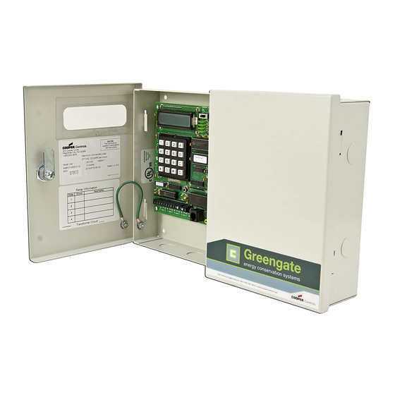
The LiteKeeper-4® is shipped in one package and
is configured with a 120V transformer or a 277V
transformer. The four relays are mounted in the high
voltage compartment. The logic board and inputs are
located in the low voltage compartment. The doors, when
shut, form a barrier between the high and the low voltage
compartments. The following information describes the
LiteKeeper 4® installation. For programming information,
refer to the LiteKeeper Keypad Programming Manual.
Getting Started
1.
Do not discard these installation instructions. Please
keep for future reference and operation information.
2.
Always disconnect all power before wiring.
3.
Use only as intended and at the listed voltage.
4.
All installation service must be performed by qualified
personnel or service technicians.
5.
Install in accordance with National Electrical Code
and any other codes that may apply.
6.
High Voltage is present inside the lighting enclosure.
Use extreme caution when performing maintenance
on this equipment. Failure to follow this warning and
use proper safety procedures could result in severe
injury or death and/or damage to the equipment.
7 .
Document all wiring that is terminated to the relays
so that the lighting control equipment can be properly
configured and programmed for operation.
8.
It is recommended that all low voltage wiring be
done with power removed to the logic board to
protect components from potential shorts during the
wiring process.
Model# LK4-120-NO
Model# LK4-277-NO
Mounting in the Enclosure
1.
Choose a dry location convenient to the circuit
breaker panel.
2.
Mount the panel on a firm surface using predrilled
holes.
3.
Connect the enclosure to the circuit breaker panel
using conduit into the punch holes provided.
4.
Remove all cuttings and dirt.
N
ote:
Make certain that high voltage and low voltage
wiring enters the enclosure separately. High
voltage wiring should be brought into the right
section of the enclosure. low voltage wire should
enter in the low voltage wiring compartment on
the left side of the enclosure.
Failure to separate high voltage from low voltage wiring
may cause interference with logic board function.
LIGHTING CONTROL
12:00 01/01/08
1
2
3
A
4
5
6
B
7
8
9
C
*
0
#
D
Low Voltage
Wiring Compartment
LK4 High Low Voltage
INS #
High Voltage
Wiring Compartment
Advertisement
Table of Contents

Related Manuals for Greengate LiteKeeper 4

Summary of Contents for Greengate LiteKeeper 4
- Page 1 Connect the enclosure to the circuit breaker panel compartments. The following information describes the using conduit into the punch holes provided. LiteKeeper 4® installation. For programming information, Remove all cuttings and dirt. refer to the LiteKeeper Keypad Programming Manual. ote: Make certain that high voltage and low voltage wiring enters the enclosure separately.
-
Page 2: Relay Wiring
Connection of 2 pole circuits/loads to the relay will void the equipment warranty and may result in severe injury The LiteKeeper 4® logic board can support up to 4 dry or death, and/or damage to the equipment. contact closure switch inputs. Regardless of input type used, it is recommended that all input wiring be done prior Relay ratings are 120 or 277 volt, 20 amp maximum. -
Page 3: Applying Power
This section describes the wiring for dry contact closure Wiring devices. There are four switch input wiring terminals on the bottom side of the LiteKeeper 4® low voltage section to allow for wiring of the dry contact closure devices. Use 18 AWG twisted, unshielded wire for all low... -
Page 4: Repair Information
System Reset and Clear Commands Repair Information Under certain circumstances, you may want to reset the If a repair becomes necessary on your LiteKeeper 4® unit, LiteKeeper 4®. There are two different types of reset please refer all service to Greengate technical support line commands available in the LiteKeeper 4®... -
Page 5: Renseignements Généraux
Renseignements généraux Renseignements généraux ote: Assurez-vous que les câblages de haute tension et de basse tension entrent séparément dans le boîtier. Le câblage de haute tension doit passer dans la Le LiteKeeper-4MD est expédié dans une seule boîte section droite du boîtier. Le câblage de basse tension et est configuré... - Page 6 20 A maximum. Charge Les borniers des relais ont une limite maximum de 10AWG pour le câblage. Câblage du relais du LiteKeeper 4 Câblage du relais ote: Les fils neutres se terminent à l’intérieur du panneau Brancher les entrées de basse tension d’éclairage adjoint.
- Page 7 être contrôlées par le commutateur ALL ON/AUTO/ALL OFF , au besoin. Il est possible d’utiliser des capteurs d’entrée photodétecteur et Greengate conjointement avec le système de contrôle d’éclairage. Le LiteKeeper 4MD est Relais de contrôle manuel capable d’alimeter plusieurs de ces dispositifs. Veuillez consulter le tableau ci-dessous pour les détails sur le...
- Page 8 L ’affichage sera en blanc et Si vous avez besoin d’une réparation sur votre dispositif ensuite indiquera « en cours de réinitialisation» LiteKeeper 4, veuillez communiquer avec le soutien technique au 1-800-553-3879. La commande de suppression des paramètres: commande de suppression des paramètres est utilisée pour...
-
Page 9: Información General
Información general Información general Extraiga todos los fragmentos y suciedad. ote: Asegúrese de que los cables de alto y bajo voltaje El panel de control LiteKeeper-4® viene en un solo embalaje ingresen al recinto por separado. Los cables de y está configurado con un transformador de 120 V o 277 V. alto voltaje deben llegar a la sección derecha del Los cuatro relés vienen montados en el compartimiento recinto. - Page 10 Carga Los bloques de terminales del relé tienen un límite máximo de cable 10 AWG. Cableado del relé Cableado del relé del LiteKeeper 4 ote: Los neutros terminan dentro del panel de iluminación contiguo. Conexión de las entradas de bajo voltaje El relé...
- Page 11 Notas sobre el fotosensor del contacto de entrada y sobre el sensor Greengate sección de bajo voltaje del LiteKeeper 4® para permitir el PPS5 cableado de los dispositivos de cierre por contacto seco. Negro Utilice cables trenzados 18 AWG, no apantallados, para realizar el cableado de todo dispositivo de cierre por contacto seco de bajo voltaje.
- Page 12 Información de reparación comandos En caso de requerirse una reparación de la unidad LiteKeeper 4, comuníquese con el área de Soporte Técnico En ciertas circunstancias, tal vez se desee reconfigurar de Greengate al 1-800-553-3879. el panel LiteKeeper 4®. Existen dos tipos diferentes de controles de reconfiguración disponibles en el sistema...
Need help?
Do you have a question about the LiteKeeper 4 and is the answer not in the manual?
Questions and answers