
Related Manuals for Promax FA-853

Summary of Contents for Promax FA-853
- Page 1 FA-853 LINEAR PROGRAMMABLE DC POWER SUPPLY Test Equipment Depot - 800.517.8431 - 99 Washington Street Melrose, MA 02176 - TestEquipmentDepot.com - 0 MI2105 -...
- Page 2 SAFETY NOTES Read the user’s manual before using the equipment, mainly "SAFETY RULES" paragraph. on the equipment means "SEE USER’S MANUAL". In this The symbol manual may also appear as a Caution or Warning symbol. WARNING AND CAUTION statements may appear in this manual to avoid injury hazard or damage to this product or other property.
- Page 3 SAFETY RULES * Use this equipment connected only to systems with their negative of measurement connected to ground potential. * This is a Class I equipment, for safety reasons plug it to a supply line with the corresponding earth connection. * This equipment can be used in Overvoltage Category II installations and Pollution Degree 1 environments.
- Page 4 Symbols related with safety: Descriptive Examples of Over-Voltage Categories Cat I Low voltage installations isolated from the mains. Cat II Portable domestic installations. Cat III Fixed domestic installations. Cat IV Industrial installations. July 2016...
-
Page 5: Table Of Contents
T A B L E O F C O N T E N T S 1 INTRODUCTION ..................1 1.1 Description ................1 1.2 Features and benefits..............1 2 OPERATION..................2 2.1 Front/Rear Panel ................ 2 2.1.1 User Interface ................ 5 2.1.2 Status Icons................ - Page 6 7 MAINTENANCE ................28 7.1 Instructions for returning by mail..........28 7.2 Cleaning Recommendations ............28 July 2016...
-
Page 7: Introduction
FA-853 1 INTRODUCTION Description FA-853 product are new high-performance programmable linear DC power supplies. The excellent features of this series include up to 100 output groups with configurable timer, high-resolution LCD display, extremely clean ripple and noise, comprehensive over-voltage over-current over-temperature protection, user friendly interface and panel layout, and variety standard interfaces to meet diverse test requirements. -
Page 8: Operation
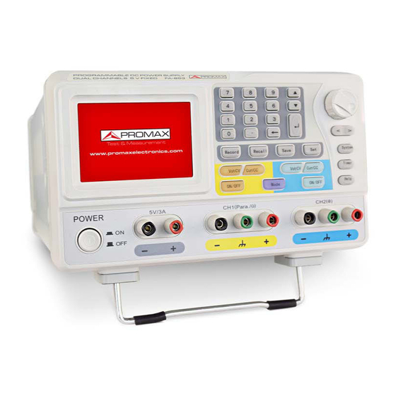
2 OPERATION Front/Rear Panel Figure 1. Front panel description. LCD: Display the user interface. Numeric keys area: Parameter input, include the numeric keys, decimal point and backspace key. Up and down direction key: Select menu or change the parameter. Enter key: Enter menu or confirm the parameter entered. Knob: Select menu or change the parameter, pressing it has the same effect as pressing the enter key. - Page 9 Channel 2 control area: Blue key: Set the output voltage of Channel 2. Blue key: Set the output current of Channel 2. Blue key: Enable/disable the output of Channel 2. Output terminals of Channel 2: Channel 2 output connectors. Mode key: Switch the working mode between Independent, Parallel, Series and Plus-minus.
- Page 10 Figure 2. Rear panel description. USB Host port: Connect as a "host device" with an external USB device, such as connect a USB disk to the instrument. USB Device port: Connect as a "slave device" with an external USB device, such as connect the instrument to a PC. COM port: Connect the instrument with external equipment as serial port.
-
Page 11: User Interface
2.1.1 User Interface Independent Mode Figure 3. User Interface description. Output status of Cannel 1. Specified time and left time of current output when the timing output of Channel 1 is on. Actual output value of power for Channel 1. Timing output mode of Channel 1 (Sequence / Loop). - Page 12 Parallel /Series Mode Figure 4. User interface in Parallel/Series mode. Maximum ratings of voltage and current. Channel status. Output mode of timing output (Sequence / Loop). Timer range. The parameter number of the current output when the timing output is Specified values of voltage and current.
- Page 13 Plus-minus Mode Figure 5. User interface in Plus-minus mode. Output status of Negative (same as Positive). Specified time and left time of current output when the timing output of Negative is on. Actual output value of power for Negative. Timing output mode of Negative (Sequence / Loop, same as Positive). Timer range of Negative (same as Positive).
-
Page 14: Status Icons
The system is in Timer Status. General Inspection After you get a new FA-853 power supply, it is recommended that you should make a check on the instrument according to the following steps: Check whether there is any damage caused by transportation. -
Page 15: Power-On Check
PROMAX distributor responsible for this business or the PROMAX local offices. If there is damage to the instrument caused by the transportation, please keep the package. With the... -
Page 16: Output Inspection
Output Inspection Output inspection is to ensure that the instrument can achieve its rated outputs and properly respond to operation from the front panel. For the procedures below, it is suggested that you read "Working Mode", "Turn On/Off the Channel Output"... -
Page 17: Working Mode
Working Mode FA-853 are designed with four working modes: Independent, Parallel, Series and Plus-minus. Press the key to switch between the four working modes. For the instructions of the user interfaces in the four working mode, please see "User Interface". -
Page 18: System Menu Operation
Note: In parallel mode, CH1 is main channel and CH2 is auxiliary channel. To ensure normal output, please connect the load to the main channel. Connecting to auxiliary channel could not ensure normal output. Series Figure 8. Plus-minus Minus Ground Plus Figure 9. - Page 19 Exit the menu Press key to close the menu or the pop-up box. Note: In this document, [System → CH1 → O.V.P] means: Enter the CH1 item in System menu, and then choose the O.V.P submenu. July 2016...
-
Page 20: Panel Operation
3 PANEL OPERATION Turn On/Off the Channel Output Independent Mode Press the key to turn on/off the Channel 1 output. Press the key to turn on/off the Channel 2 output. The ON/OFF key is lighted when the corresponding channel is on. Parallel, Series and Plus-minus Mode Press the key to turn on/off the channel output. -
Page 21: Over Voltage/Current Protection
Parallel/Series mode Press the key, the input box of output voltage/current will pop up. The operation of input box is the same as Independent mode. Plus-minus mode Press the key, the input box of Negative output voltage/current will pop up. The operation of input box is the same as Independent mode. -
Page 22: Set O.v.p
3.3.1 Set O.V.P Enter the O.V.P setting menu: Independent Mode Press the key, enter [System → CH1 (CH2) → O.V.P]. Parallel, Series Mode Press the key, in normal status, enter [System → O.V.P]; in timer status, enter [System → Pro Set → O.V.P]. Plus-minus Mode Press the key, enter [System →... -
Page 23: Timing Output
Use the numeric keys to enter the O.C.P value in current mode and status. The maximum in Independent, Series and Plus-minus mode is 3.15 A, the maximum in Parallel mode is 6.3 A. Press the key to confirm. Timing Output The timing output function can preset up to 100 groups of timing parameters. - Page 24 Figure 10. Timer Setting Interface in Independent Mode. The selected parameter will be highlighted. In Independent mode or Plus-minus mode, press key to select the left parameter area, press to select the right parameter area. Press the key to change the parameter item. After selecting the parameter, use the numeric keys to enter a desired value, press the key to confirm.
-
Page 25: Timer Range
3.4.3 Timer Range Timer range setting denotes that you can set the last number of timer parameter group and output mode. You can find out the TimerRng submenu of system menu only in timer status. If turn on the timing output, the system will output the pre-set parameters between 0 and the set number at sequence or loop mode. -
Page 26: Save/Recall/Record
Save/Recall/Record This instrument support operations with a USB flash device and local file storage, including: store, recall and delete current setting parameters. The current data of the channel can be recorded into a txt file, which stored in USB disk. You can connect the USB disk to the USB Host interface. -
Page 27: Record The Output
3.6.2 Record the Output You have to insert a USB disk before using this function. By pressing the key, the current data of the channel can be recorded into a txt file, which stored in USB disk. Press the key; press the numeric keys to set the interval. Press the key to start recording. -
Page 28: Set System Time
3.7.4 Set System Time Press the key and enter [System → Sys Set → SysTime]. Press the key or turn the knob to set the selected value. Press the to move the cursor. Press the key to confirm. 3.7.5 Buzzer key and enter [System →... -
Page 29: Use Built-In Help
Menu Item Defaults Brightness Screen Saver Buzzer Use Built-in Help Press function button, the catalog will display in the screen. Press the key or turn the knob to choose help topic. Press the key to view the details about the topic; press the to go back to the catalog. -
Page 30: Communication With Pc
4 COMMUNICATION WITH PC FA-853 Power Supply supports communications with a PC through USB or COM interface. You can use the communication software to set the parameters, control the output of the power supply, and synchronously display the actual output values on the Power Supply screen. -
Page 31: Troubleshooting
Restart the instrument after the steps above. If the problem still exists, please contact PROMAX for our service. The output is abnormal: Check if the output voltage is set to 0 V. If so, set it to other value. -
Page 32: Specifications
6 SPECIFICATIONS The specifications below are based on the instrument having run for at least 30 minutes continuously under the specified operating temperature. Channel 1/Channel 2 Fixed 5V Independent/Parallel 0 to 30 V Voltage Series 0 to 60 V Plus-minus 30 V 30 V DC Output Ratings Independent/Series... - Page 33 Display Display Type 3.9 inch colored LCD (Liquid Crystal Display) Display Resolution 480 (Horizontal) × 320 (Vertical) Pixels Display Colors 65536 colors, TFT screen Power Supply 110 Vac ± 10%, 220 Vac ± 10%; AC input 50/60 Hz 110 V 125 V-F5A Fuse 220 V...
- Page 34 7 MAINTENANCE Instructions for returning by mail Instruments returned for repair or calibration, either within or out of the warranty period, should be sent with the following information: Name of the Company, name of the contact person, address, telephone number, receipt (in the case of coverage under warranty) and a description of the problem or the service required.
- Page 35 PROMAX ELECTRONICA, S. L.
Need help?
Do you have a question about the FA-853 and is the answer not in the manual?
Questions and answers