Table of Contents
Advertisement
Quick Links
Advertisement
Table of Contents

Related Manuals for SystemBase uCAN View

Summary of Contents for SystemBase uCAN View
- Page 1 View English Manual September 15, 2014 Version 2.0...
- Page 2 History Date (MM/DD/YYYY) Version Pages Description 09/15/2014 Revised 11/18/2013 Copyright 2014 SystemBase Co., Ltd. All rights reserved. Website: http://www.sysbas.com/ Technical Support: http://www.solvline.com/ Phone: +82-2-855-0501 FAX: +82-2-855-0580 16F Daerung Post Tower-1, 288, Digital-ro, Guro-gu, Seoul, Republic of Korea If you have any questions, please post your inquiries at Solvline.
-
Page 3: Table Of Contents
Index Index 1. uCAN View ............................5 1.1. Introduction ..............................5 1.2. uCAN ................................5 1.3. Device Recognition ..........................6 1.4. System Requirement ..........................7 2. Installation and Execution ......................8 2.1. Installation ..............................8 2.2. Execution ..............................11 3. Main Window ..........................12 4. - Page 4 Index 7.1. Connection Status ..........................24 7.2. Connected Device ..........................24 7.3. Error Status ............................... 25 8. Error Status ............................26 9. Troubleshoot ............................ 27 10. Appendix ............................28 10.1. Baud rate ..............................28...
-
Page 5: Ucan View
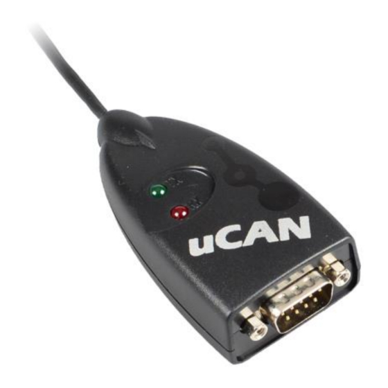
1. uCAN View 1.1. Introduction The uCAN View is an Microsoft Windows based analyzer for uCAN device to probe all transmitted data in the CAN bus. It does not require a separate driver to operate. The users can see all the CAN data from the provided utility. -
Page 6: Device Recognition
View Terminal Resistor switch on the bottom of uCAN device. Switch 1 Switch 2 Description Enable Terminal Resistor Disable Terminal Resistor (Default) Not used Not used 1.3. Device Recognition This device will be recognized by Windows as ‘HID-compliant device’ or ‘USB Input Device’. -
Page 7: System Requirement
View 1.4. System Requirement Minimum System Requirement : Intel Pentium 1GHz (32bit) RAM: 512MB : Windows XP SP2 Disk Space : 10MB additional space for the utility to function Supports HID (Human Interface Device) 1360 x 768 Display (Monitor) required. -
Page 8: Installation And Execution
Installation 2. Installation and Execution 2.1. Installation 2.1.1 Insert included CD into your computer. 2.1.2 Go to [CD Drive]\uCAN View and run “uCAN View setup.exe” file. 2.1.3 Install the uCAN View utility. - Page 9 Installation...
- Page 10 Installation 2.1.4 After above process is completed, the short cut will be created under “SystemBase” in the Program group under Start menu and at the desktop screen. * Windows 8/Server 2012 or greater versions may not show the icons under the folder.
-
Page 11: Execution
Execution 2.2. Execution 2.2.1. Depending on the icon location or the operating system, click or double click the “uCAN View” icon to run the utility. 2.2.2. The uCAN View main window will appear as shown below. -
Page 12: Main Window
Main Window 3. Main Window There are five parts in the main window. Name Description Title Name of the utility is displayed. Menu Various functions and features can be accessed from here. Connection status of uCAN device, short cut icons of functions, and Control bar numbers of CAN frames are displayed. -
Page 13: Menu
Menu 4. Menu There are three main menus shown here. Name Description File Open/Save DCU file. Function Sort or filter CAN frames in client view windows. Run ‘exerciser’ function. Help Displays the version of the utility. 4.1. File When ‘File’ menu is clicked, following sub-menus will appear. - Open Log: Open DCU file to read CAN frame data. -
Page 14: Exerciser
Menu 4.2.1. Exerciser The users can define CAN frame and send it through uCAN. (Provides manual or automatic transmission mode) Name Description Type of CAN frame. STD DATA: CAN Standard Data Frame TYPE STD REMOTE: CAN Standard Remore Frame EXT DATA: CAN Extended Data Frame EXT REMOTE: CAN Extended Remote Frame CAN frame ID (Hex Value) ID(Hex) - Page 15 Menu [When disabled by unchecking ‘Enable’ check box.] [When enabled by checking ‘Enable’ check box.] Name Description Input Frame Define CAN frame that Response funtion will respond by. (Receive) Response Define CAN frame that Response function will respond with. Frame (Transmission) Enable Enable ‘Response’...
-
Page 16: Sort
Menu 4.2.2. Sort Click "Disconnect" button to use this function. - CAN frame can be sorted with number of the CAN frame or ID by ascending or descending order. -
Page 17: Filter
* When data is saved while filter function is enabled, all data is saved instead of just filtered data. Selection: CAN ID transmitted/received from uCAN View can be selected to be displayed. - Included: Display frames related to these CAN IDs. -
Page 18: Help
Menu 4.3. Help When ‘Help’ menu is clicked, following sub-menu will appear. - About uCAN View: The current version of the utility is displayed. -
Page 19: Control Bar
5.1. Connect / Disconnect Button When ‘Connect’ button is clicked, recongnized devices are shown in the list box from the ‘Connection Setting’ window. While uCAN View utility is running, when uCAN device is connected to the computer, ‘Connecting Setting’ window will pop-up. -
Page 20: Count
Control Bar 5.2. Count Shows the number of transmitted/received CAN frames by uCAN device. Name Description Displays the number of CAN frames transmitted by the uCAN device Displays the number of CAN frames received by the uCAN device 5.3. Clear Reset the count of Tx/Rx to zero. -
Page 21: Setup
Control Bar 5.5. Setup Click ‘Setup’ to open ‘uCAN Setup’ window. (For more information regarding baudrate, please refer to chapter 10.1 Baudrate.) Name Description The name of current device can be changed. (Default: Serial1234) uCAN Serial 영문이나 숫자로 최대 10자로 제한됩니다. Preset CAN baud rate can be selected. -
Page 22: View
View 6. View ‘No.’ means numbers of each frame. In one page there are maximum 25 frames displayed. Arrows pointing up or down can be clicked to scroll the screen. 6.1. Frame Each blocks of line represents one CAN Frame. Name Description Order of incoming frame... -
Page 23: Detailed Frame View
View 6.2. Detailed Frame View When each data frames are clicked from ‘Client View’ window, detailed frame information displays as shown below. Previous Frame: Displays previous detailed frame information. Next Frame: Displays next detailed frame information. SOF: Stands for ‘Start of Field’ which means the beginning of the frame. ID: It is a CAN Identifier used for prioritizing or used for user-defined content.. -
Page 24: Status Bar
Displays current connected status Name Description Connection Status Shows whether uCAN View is connected to the uCAN device. Connected Device Shows the ID of the uCAN device and the USB mode Baud Rate Shows the CAN baud rate set for the connected uCAN device. -
Page 25: Error Status
Status Bar 7.3. Error Status Icon Description uCAN View and uCAN devie is not connected. Connected with uCAN CAN frame transmitted from uCAN CAN frame received from uCAN CAN frame transmitted/received from uCAN Error Count of uCAN is greater than 0. -
Page 26: Error Status
Error Status 8. Error Status Error Status window shows error status of uCAN device. Name Description Internal TEC (Transmit Error Count) in uCAN device. Internal TEC (Receive Error Count) in uCAN device. Last error count from uCAN device Current error mode in uCAN device. Error Mode (Active, Passive, Bus-Off Mode) Stuff Error... -
Page 27: Troubleshoot
(D) Check if the buffer is full. For stability issue, maximum 50,000 frames are set to be the limit. Clear the buffer to receive any data. 9.1.2. The uCAN device cannot be found by the uCAN View utility. Solution: (A) Please disconnect the uCAN USB cable then reconnect to the computer. -
Page 28: Appendix
Appendix Appendix 10.1. Baud rate Parameter Range Function 1~32 Set size of 1T Used in CAN Bus to synchronize various nodes. SYNC_SEG Size is fixed to 1T Compensates for physical delay times. (Physical bus and PROP_SEG (1~8) x T internal CAN node transmission delay) Used to correct Phase Edge Error. - Page 29 Appendix Example) Baud rate Sample Point ClkDiv TSEG1 TSEG2 50 % 53.33 % 50 % 50 % 53.33 % 1000 53.33 %...
Need help?
Do you have a question about the uCAN View and is the answer not in the manual?
Questions and answers