Table of Contents
Advertisement
Quick Links
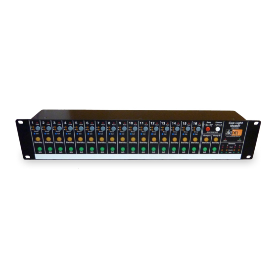
16 Channel Cue Light System
A visual signalling system for theatres that allows
silent cues to be given to actors and technicians
•
Up to 40 programmable Cue Lights
•
Multiple Cue Lights per channel
•
2,000m (6500ft) total cable length
•
Uses a single 1 pair cable
•
Simultaneous control from two Master Stations
www.LeonAudio.com.au
01.
Advertisement
Table of Contents

Summary of Contents for Leon Audio Cue Light Master
- Page 1 16 Channel Cue Light System A visual signalling system for theatres that allows silent cues to be given to actors and technicians • Up to 40 programmable Cue Lights • Multiple Cue Lights per channel • 2,000m (6500ft) total cable length •...
- Page 2 Quick Start Guide • Using a standard 3 pin XLR microphone cable onnect one or more Outstations to either XLR connector on the Master Station’s rear panel. Both XLRs on the Master can be used at the same time. • Both Go and Standby lamps on the Master will light dimmed once the Outstation has performed a lamp test.
- Page 3 Index Quick start Guide Diagnostics The Cue Light Components System design suggestions. PCinterface QL-PCi Mk4 Why not use bigger buttons? Work-Light Outstation QWL-xx Mk4 Specifications 16 Channel Master Station. QLM16 Mk4 Warranty Dual Master Stations Cue Light Outstation types and configuration Cue Light Outstations Standard Outstation.
- Page 4 Details on page 8 • 20mm Go and Standby LED lamps are b right, wide angle • 16 channel digital Cue Light Master Station can be used with and dimmable. any number of Cue Light Outstations from 1 to 40.
- Page 5 Cue Light Components (continued) Small Footprint Cue Light Model QLS-SM Mk4 Relay Outstation Small Footprint Cue Light with Beeper Model QLS-SM-B Mk4 Small Footprint Cue Light Relay Outstation QLS-SM Mk4 QLR Mk4 Details on page 17 Details on page 22 •...
-
Page 6: Contact Sensor
Cue Light Components (continued) Contact Sensor RS232/RS485 Computer interface Contact Sensor PCinterface QTS Mk4 QL-PCi Mk4 Details on page 25 • • Allows monitoring of remote switch contacts such as used Connects between the Master Station and a PC running on a theatrical trap door lock. - Page 7 Cue Light Components (continued) Work-Light 600mW Work-Light QWL-BL Mk4 (Blue LEDs) QWL-WH Mk4 (White LEDs) Details on page 28 • Powered by the Cue Light system, it connects just like a Coming Soon standard Cue Light Outstation. • Ethernet bridge. •...
- Page 8 16 Channel Master Station QLM16 Mk4 The Cue Light system consists of a Master Station and any Up to 6 Master Stations can be linked for larger systems. number of Cue Light Outstations from 1 to a maximum of 40. Each Master Station must have its own wiring universe of 16 channels.
- Page 9 16 Channel Master Station (continued) Contact Sensor Outstations Eavesdrop Outstations The Contact Sensor Outstation QTS Mk4 allows remote On any channel, set only one Outstation to Normal Mode. monitoring of voltage free switch contacts such as used on This Outstation will send return monitoring to the Master a theatrical trap door’s lock.
- Page 10 16 Channel Master Station (continued) Fault lamps A red Fault lamp at the top of each channel indicates when an Outstation is not communicating with the Master Station. This could be due to an unplugged Outstation or a cable fault. The Fault lamp has 3 states.
- Page 11 16 Channel Master Station (continued) Power. Parallel XLR connectors for 36V DC 1.9A Outstations Parallel Expansion Ports Master’s Mode switch. for PCinterface and Used when 2 Masters the linking of Masters are connected Group buttons Master Station’s rear panel The group feature allows cues across multiple channels to be triggered by the press of a single button.
-
Page 12: Beep Button
16 Channel Master Station (continued) Short lamp The Short lamp indicates short circuits on the external XLR wiring. Fault current is electronically limited to approximately 1.6 amps. If the short is maintained for more than 400mS, the power supply enters a hiccup mode where power to the Outstations is turned off and reapplied once every few seconds until the fault is cleared. -
Page 13: Expansion Port
16 Channel Master Station (continued) Master Mode Switch Parallel XLR Power. connectors for 36V DC 1.9A When two Master Stations are connected to the same wiring Outstations universe for dual control of the same 16 channels, set the Master Mode switch on one Master Station to Main and to Slave on the second Master Station. - Page 14 16 Channel Master Station (continued) Quick Start Guide for Dual Master Stations Two Master Stations can be connected to the same Cue Typical applications include using a second Master Station Light wiring universe allowing for control of 16 channels when a stage manager’s sight lines are blocked and also at from both Master Stations at the same time.
-
Page 15: Typical Application
16 Channel Master Station (continued) Dual Master Stations Power When a Master Station is running solo, the Mode switch Only one of the two Master Stations needs to have its mains power supply connected. It does not matter which one. The position does not matter. - Page 16 Different types of Outstation (QLS, QLR or QTS) can be There are currently 3 main different types of Outstation that connected to the same channel at the same time but only can be connected to the Cue Light Master Station. • one type will be operational.
-
Page 17: Typical Operation
Cue Light Outstations The Beeper Outstations can be used as a Standard Standard QLS Mk4 Outstation. They only beep when the red Beep button on Standard + beeper QLS-B Mk4 the Master Station is pressed in conjunction with the Go or Standby button on the required channel. -
Page 18: Technical Note
Standard Outstations (continued) Anywhere from 1 to 40 Outstations can be connected to the The 2mm steel outer case has a total of 6 mounting holes Master Station. Any number of these Outstations can be including a 10mm hole for attaching a hook clamp. connected to any channel. - Page 19 Standard Outstations (continued) • Standby Flash on Master The following Outstation options can be programmed Default setting is to flash. individually for each channel from the Master Station. If the Outstation’s standby lamp is set to not flash, it is To change any of these settings, see the Master’s desirable to have the Master Station’s lamp flash so that an Configuration Editor on page 41.
- Page 20 Standard Outstations (continued) • • Go Latches Acknowledge button back-light Default setting is to latch. Default setting is to be lit. If set to unlatched (momentary action), the Go lamp will The Acknowledge button’s back-light can be turned off. only be lit for as long as the Master Station’s Go button is One well known circus uses the Outstations to indicate the pressed.
- Page 21 Multiple Outstations per channel Important Eavesdrop Mode On any one channel: Set one Outstation to Normal Mode. One might use multiple Outstations assigned to the same Set all additional Outstations to Eavesdrop Mode. channel for some permanent function such as the fly floor, leaving the two Groups (A &...
- Page 22 Relay Outstation QLR Mk4 The Relay Outstation provides two voltage free changeover relay contacts controlled by the Master Station. Relay A is controlled by the Standby button. Relay B is controlled by the Go button. The relay contacts are rated at 2 amps 30 volts AC or DC. An external normally open momentary acting Acknowledge button may be connected if required.
- Page 23 Relay Outstation (continued) Multiple Relay Outstations can be used on the same channel by setting additional Outstations to Eavesdrop Mode. See Multiple Outstations per channel (page 21). Changing the mode via the front panel of a Relay Outstation will simultaneously change the mode of all Relay Outstations connected to that channel.
- Page 24 Relay Outstation (continued) Wiring examples for the Relay Outstation Bright Outdoor Cue Light Idea Relay A Power Supply to suit lamp 12-24V Lamp(s) 2 Amps max. Relay B Power supply QLR Mk4 to suit lights Relay Outstation Relay Outstation driving a low voltage lamp 12-24V Relay Coil Relay A...
- Page 25 Sensor Outstation QTS Mk4 The Sensor Outstation was originally developed for monitoring Sensor Outstations 1- 4 have a dedicated display on the switch contacts on the locks of theatrical trap doors. Master Station. This Outstation monitors a single pole voltage free switch The status of the monitored switch contact is displayed on contact and displays its status on the Master Station.
- Page 26 Sensor Outstation (continued) Circuit A (No End Of Line Resistors) The switch contacts to be monitored are wired across the two outer terminals of a green 3 way Phoenix connector on the Sensor Outstation. The centre Phoenix terminal is monitored not used.
- Page 27 Sensor Outstation (continued) Circuit B (Recommended) Depending on the design of the switch used and the physical installation, the End Of Line Resistors can be installed directly on the switch or on a terminal block monitored Cable faults switch adjacent to the switch. in switch wiring are monitored.
- Page 28 600mW Work-Light Outstation The Work-Light Outstation provides low level lighting for The Work-Light can be turned on/off by a channel on the backstage and understage areas etc. Master Station or it can be set to be on all the time by Powered by the Cue Light system, it connects just like a setting its address to channel 17.
- Page 29 Changing an Outstation’s channel ... without the use of any tools or switches An Outstation’s channel number is stored in the Outstation in non-volatile EEPROM memory so that it will be remembered even when the power is off. Press & hold the Acknowledge button while plugging in the Outstation’s XLR cable.
- Page 30 Outstation Cables Design objective: It is suggested that the Cue Light system be restricted to a Wire up the venue in any manner using almost any type of maximum of about 40 Outstations and a total of 2,000m three core cable, and then plug anything in anywhere. (6500 ft) of cable.
- Page 31 Outstation Cables (Continued) Wire Size The size of the copper wire in a cable determines the There are literally hundreds of different cable types that are suitable for use with the Cue Light system. voltage drop on that cable. Larger copper wires decrease The two primary cable characteristics of interest for the Cue the voltage drop and allow for longer cable runs with more Outstations connected.
-
Page 32: Cable Capacitance
Outstation Cables (Continued) Cable Capacitance Cable capacitance reduces the amplitude of the data Cables using PVC insulation for the inner conductors have signal by storing some of that signal as a electric charge in high capacitance and high losses for digital signals. They the cable. -
Page 33: Daisy Chain Wiring
Outstation Cables (Continued) Unused cable branches must be included in the total cable length, even if no Outstations are connected to that cable run, because the cable’s capacitance is still connected to the circuit. There are three basic wiring configurations; these are daisy chain, star and loop. - Page 34 Outstation Cables (Continued) Star wiring Loop wiring At the star point, all the cables are simply wired in parallel. Loop wiring has the advantage that when a cable breaks or becomes disconnected, the system remains 100% This is often done at a patch panel. Don’t forget to include operational.
-
Page 35: Cable Length
Cable Length Nominal wire size (AWG) Metres 200 1000 1200 1400 1600 1800 2000 3000 4000 Feet 650 Conductor Screen 1300 2000 2600 3300 4000 4600 5200 5900 6500 9850 13100 Notes Belden 9860 Generic 14 AWG Belden 9250 (9816) Mogami 3173 Generic... - Page 36 Cat 5/6 cables CAT5/6 cable can be used but the screened variety is The star configuration is often wired using CAT5/6 cable as preferred to reduce noise pickup from adjacent cables. If the this follows the convention used for computer networks. CAT5/6 cable has a screen, tie it to XLR pin 1 at both ends.
- Page 37 Outstation Cables (Continued) A wiring example This example shows how a theatre might be permanently Patch wired using a mix of daisy chain and star wiring. Panel Backbone cable segments in green are wired with a 20AWG cable as these would have a large number of outlets attached to them.
- Page 38 Outstation Cables (Continued) 200m 200m 200m 200m 200m What’s the cable Limit? Fig 1. Cable total: 1,000m Outstations: 36 There is no magic cable length at which the Cue Light system suddenly stops operating. 100m 100m 100m 100m We have suggested that the Cue Light system be restricted to a maximum of about 40 Outstations and a total of 2,000m 100m...
- Page 39 More than 16 channels The wiring between a Master Station and its Outstations is known as a wiring universe. A Master Station and its associated universe supports a maximum of 16 channels. With Universe A multiple Outstations per channel, there may be up to 40 Master A Outstations connected to these 16 channels.
- Page 40 Linking multiple Master Stations When multiple Master Stations are used, the 4 Group Master buttons can be linked across the Masters via an Expansion Port on the Masters’ rear panels. (The group feature allows cues across multiple channels to be triggered by the press of a single button). Up to 6 Master Stations can be linked.
- Page 41 Master Station’s Configuration Editor The Configuration Editor allows the Master Station and 1: ShowTime file (read/write) individual Outstations to be customized to suit specific When the Master Station powers up, it reads the ShowTime needs. file to run the Cue Light system. After editing any file, changes must be saved to the The Configuration Editor is very simple to use once you ShowTime file if you want those settings to run the Cue...
-
Page 42: Configuration Editor
Configuration Editor Start the Configuration Editor. Editor starts with the ShowTime file opened and option #1 selected. Open one of 8 files Alternate button overlays Select options page 1 or 2 Select an Option to edit Please read pages 43 & 44 first. These pages from the grey &... - Page 43 Master Station’s Configuration Editor (continued) Starting the Configuration Editor The editing sequence is: 1: Start the Configuration Editor 2: Open one of 8 files To start the Configuration Editor, press and hold these 3 Select an option to edit buttons until the 16 blue Call lamps light (takes about 4 Edit that option on a channel by channel basis using seconds).
- Page 44 Master Station’s Configuration Editor (continued) To Open a file. Important! • Press and hold the File Open button Eight yellow buttons will light showing the 8 files that can be After editing or opening any file, the file must be saved opened.
- Page 45 Master Station’s Configuration Editor (continued) Factory User Selectable Cue Light Outstation options Default Option Options Each Outstation has a number of options that can be edited. S/by colour Yellow Outstations do not need to be connected to be able to edit a S/by Flash on Master Flashes Steady...
- Page 46 Master Station’s Configuration Editor (continued) Beep-On-Go option Editing multiple channels There are 3 beep durations that can be programmed for When more than one channel (green buttons 1-16) is each channel as well as an off option. initially selected, the red mode indicator lamps will be The Beep-On-Go Modes are: off.
- Page 47 Master Station’s Configuration Editor (continued) Dimmer option Dimmers to 100% button resets the dimmer intensity for all 16 channels to 100%. The green Edit Channel buttons are not used. There is no provision to set individual channels to intensities lower than 100%. Tip: If dimmer intensities other than 100% need to be saved to one of the User files, do the following:...
- Page 48 Master Station’s Configuration Editor (continued) Master Station options 2: Group Master buttons linked There are only 3 options specifically for the Multiple Master Stations can be linked so that a press of Master Station. one of the Group Master buttons (just to the right of channel 16) can trigger multiple cues across multiple Master 1: Master Station’s address Stations.
- Page 49 Master Station’s Configuration Editor (continued) Master Station options 3: Go Cue Duration The default settings for the Go Cue are for the Go lamp to light steady for 3 seconds and then flash for 12 seconds, giving a total Go Cue duration of 15 seconds. Example: Change the Go Cue duration.
- Page 50 Master Station’s Configuration Editor (continued) Relay Outstation options Each Relay Outstation has a number of options that can be The Relay Outstation has 5 operating modes which can be edited. Outstations do not need to be connected to be able changed from either the Relay Outstation’s front panel or to edit a channel's options.
- Page 51 Master Station’s Configuration Editor (continued) Example: Change mode for Relay #12 Relay Outstation options Assign Relay #12 to A:momentary B:Latch mode. Relay Mode Start the Configuration Editor Each Relay must be assigned to one of 5 modes. Select Page 2 Select a Relay mode from these 5 grey buttons Select A:momentary B:Latch mode When any of these buttons are pressed, two adjacent...
- Page 52 Master Station’s Configuration Editor (continued) When the Cue Light mode is selected, the following 7 options are available. All options can be programmed Cue Light Mode individually for each channel. The Cue Light mode is one of five possible modes that a Relay can be assigned to.
-
Page 53: Sensor Options
Master Station’s Configuration Editor (continued) Select an option to edit by using the yellow buttons Sensor options The button will light to indicate the selection. Edit that option on a channel by channel basis using the The Sensor Outstation has 4 options , 3 of which are Green buttons (Green button lit = option active) - Page 54 Diagnostics Button & Lamp test Outstation test This test is used to check operation of Outstation lamps, This test is used to check the operation of buttons and communication to and from the Master Station and cable lamps on the Master Station. voltage drop.
-
Page 55: Executive Summary
System Design Suggestions For Cue Light designers and consultants Some typical systems The Master Station has 16 channels for Cue Lights , but you Here are some suggested systems based on customer orders. can connect any number of Outstations from 1 to 40. Using the ability to connect more than one Outstation to the Basic systems same channel will free up the Groups which are used to... - Page 56 Why not use bigger buttons? The Cue Light Master Station uses 9.5mm (3/8") diameter By using a larger 19mm square button as shown on buttons. channels 6-8, the target area is reduced to 22mm x 22mm Having a reasonable space between the buttons lessens before a false button press may result.
-
Page 57: Specifications
Specifications Master Station QLM16 Mk4 Standard Outstation QLS Mk4 Lamps Outstation Connectors 20mm diameter lamps with four LEDs per colour. Genuine Neutrik XLRs. 3 pin male and female in parallel Connectors Power Genuine Neutrik XLRs. 3 pin male and female in parallel 70 watts maximum. - Page 58 Specifications Small Footprint Cue Light QLS-SM Mk4 Relay Outstation QLR Mk4 Lamps Connectors 20mm diameter lamps with four LEDs per colour. Genuine Neutrik XLRs. 3 pin male and female in parallel Connector Power Permanently attached 1m Canare cable fitted with a 3 pin Powered from the Master Station via the XLR data cable male XLR.
- Page 59 Specifications Work-Light Outstation QWL-xx Mk4 Lamps 20mm diameter lamps with multiple LEDs per lamp. Connectors Genuine Neutrik XLRs. 3 pin male and female in parallel Power Powered from the Master Station via the XLR data cable Dimensions Width: 92mm (3.7”) Length (excluding connectors): 148mm (5.8”) Height: 38mm (1.5”) Chassis...
-
Page 60: Warranty
62 Edgewar e Road, Aldgate South Australia, 5154 Warranty Phone: 08 8339 3865 The Leon Audio Cue Light System is guaranteed for five Mobile: 0419 826 262 years from date of original purchase against defects in workmanship and materials. International...
Need help?
Do you have a question about the Cue Light Master and is the answer not in the manual?
Questions and answers