Advertisement
Quick Links
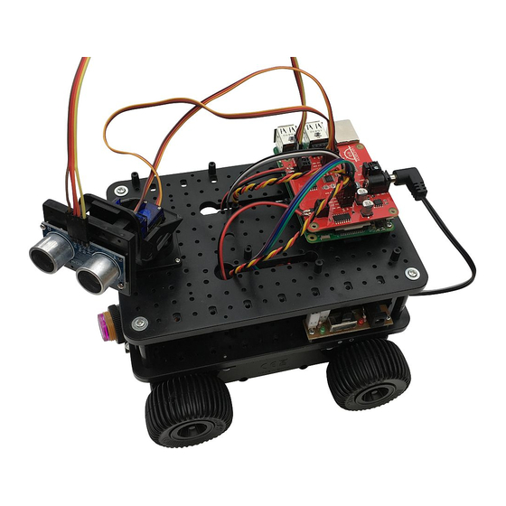
Ultimate Initio kit for Raspberry Pi
You should already have followed the instructions for assembling the Initio chassis.
In this section we will add the Pirocon2 controller, the obstacle sensors, line sensors and the
pan/tilt assembly with ultrasonic sensor.
The (optional) iBoost64 is also used to boost incoming signal strength and resolve issues with
marginal IR sensors, including the wheel sensors on the Initio
Quickstart Pinout Description
If you use the recommended iBoost64 input signal booster, then we can connect the 8 I/O
signals as follows:
Pin 7 - Left Obstacle sensor
•
Pin 11 - Right Obstacle sensor
•
Pin12 - Left Line sensor
•
Pin 13 - Right Line sensor
•
Pin 15 - Left Wheel sensor 1 (Optional)
•
Pin 16 - Right Wheel sensor 1 (Optional)
•
Pin 18 - Tilt Servo (Output - not connected to iBoost64)
•
Pin 22 - Pan Servo (Output - not connected to iBoost64)
•
Advertisement

Related Manuals for 4tronix Ultimate Initio kit


Summary of Contents for 4tronix Ultimate Initio kit
- Page 1 Ultimate Initio kit for Raspberry Pi You should already have followed the instructions for assembling the Initio chassis. In this section we will add the Pirocon2 controller, the obstacle sensors, line sensors and the pan/tilt assembly with ultrasonic sensor. The (optional) iBoost64 is also used to boost incoming signal strength and resolve issues with...
- Page 2 1. Fitting the Pirocon to the Raspberry Pi Screw the support pillar to the underneath of the Pirocon. The position shown above is suitable for a Raspberry Pi Model B+, Model A+ or Raspberry Pi 2 Model B Use the hole in the centre if using a Model A or Model B Push the Pirocon carefully onto the GPIO pins of the Raspberry Pi, ensuring the pins are placed correctly as shown in the photo above Connect the motor wires as shown.
- Page 3 It won't damage it if you connect them differently, but the example programs won't go the direction that you would expect Plug the Black/White cable with the DC Jack into the left-most pins on the switch PCB on Initio and the DC Jack end into the Pirocon as shown above. Check all the wiring again very carefully, then now is a good time to see if the Pi powers up and you can control the motors.
- Page 4 2. Mounting Obstacle Sensors Check that each sensor has 2 mounting collars. Screw one onto the body of the sensor, leaving room at the front for the second one Push the sensor through from the rear of the mounting bracket and screw on the second collar.
- Page 5 Connect to the Pirocon2 (or the iBoost64 as below) Left sensor to Pin 7 (marked x07 or #04) • Right sensor to Pin 11 (marked x11 or #17) • The wire colours from the obstacle sensor are: Red: 5V • Black: Gnd •...
- Page 6 3. Mounting the Line Sensors First, take the 30cm female-female jumper strip of 10 wires and split it into three strips: Brown, Red, Orange, Yellow (this is for the Ultrasonic Sensor) • Green, Blue, Purple (this is for the Left Line Sensor) •...
- Page 7 Connect the Green, Blue, Purple wire to the Left Sensor and the Grey, White, Black cable to the Right Sensor ** Note some sensors have the pins in order 5V, Signal, Gnd; other have them in order Signal, 5V, Gnd - make sure you know which wire colour is connected to which. Connect the sensors to the Pirocon or iBoost64 (shown below) Left sensor to Pin 12 (marked x12 or #18) •...
- Page 8 4. Connecting the Pan/Tilt Assembly This is now supplied fully assembled with the Initio Ultimate kit. If you have an unassembled one, then please visit the assembly instructions here (opens in new window) Take 4 of the 2.0x6PB screws (these are the smallest ones in the packet and there are 6 of them) Screw the base of the pan/tilt assembly to the upper plate in the position shown Rotate the pan/tilt carefully left and right to access the screw holes...
- Page 9 Connect the Pan servo (bottom servo) to Pin 22 (marked x22 or #25) Connect the Tilt servo (upper servo) to Pin 18 (marked x18 or #24) Note the colours of the servo wires and ensure they are connected correctly: Black: Gnd •...
- Page 10 Screw the saddle clamp over the cable terminals as shown above Clip the whole assembly to the front of the Pan/Tilt assembly as shown above Note that you can purchase additional clip-on mounts so you could mount a camera on one and simply clip it off to change from Ultrasonic to Camera Connect the other end of the cable into the ultrasonic pins located between the 2 motor terminals...
- Page 11 The main build of your Ultimate Initio Kit for the Raspberry Pi is now complete. 6. Connecting the Wheel Sensors (Optional) Note that the wheel sensors require additional code to operate properly that is not included in the python library.
Need help?
Do you have a question about the Ultimate Initio kit and is the answer not in the manual?
Questions and answers