Advertisement
Quick Links
Safety
Technology
& Innovation
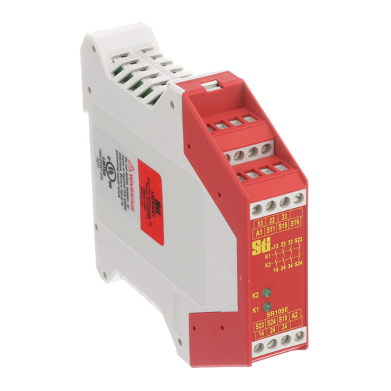
SR105E
User Information for SR105E
Correct Use
The SR105E contact block in combination with any basic device
from the OMRON STI SR series can be used to produce up to
three additional safety contact paths per device. An existing
system can thus be expanded practically indefinitely in a modu-
lar manner. Activation takes place via a safety contact of the
basic device. The SR105E provides signaling contacts for fault
monitoring. The devices can be used in systems up to safety
category 4, PL e.
Features
3 safe, redundant relay outputs
•
1 auxiliary contact (fault monitoring)
Activation via basic device from the OMRON STI SR
•
series
Modular, freely configurable safety system
•
Fault monitoring by basic device
•
Function
The safety expansion contact block SR105E in combination
with a basic device from the OMRON STI SR series is
designed for safe isolation of safety circuits according to
EN 60204-1 and can be used up to safety category 4, PL e
according to EN ISO 13849-1.
Terminal S11 (DC 24V control voltage) is connected with
terminals S15 and S16 via the safety contacts of the basic
device. Starting the basic device also activates the
SR105E. The basic device disconnects the control voltage
when the safety switch is operated, and the safety contacts
of the SR105E open immediately.
If a fault occurs in the SR105E, this is detected by the basic
device via terminals S23 and S24.
Independent operation without basic device is not
possible .
Installation
As per EN 60204-1, the device is intended for installation in
control cabinets with a minimum degree of protection of
IP54. It is mounted on a 35-mm DIN rail according to DIN
EN 60715 TH35.
Safety
Installation and commissioning of the device must be
•
Precautions
performed only by authorized personnel
Observe the country-specific regulations when installing
•
the device.
The electrical connection of the device is only allowed to
•
be made with the device isolated.
The wiring of the device must comply with the instruc-
•
tions in this user information, otherwise there is a risk
that the safety function will be lost.
When the 24 V version is used, a control transformer
Electrical
•
according to EN 61558-2-6 or a power supply unit with
Connection
electrical isolation from the mains must be connected.
External fusing of the safety contacts (4 A slow-blow or 6
•
A quick-action or 10 A gG) must be provided.
A maximum length of the control lines of 1000 meters
•
with a line cross section of 0.75 mm
ceeded.
The line cross section must not exceed 2.5 mm
•
If the device does not function after commissioning, it
•
must be returned to the manufacturer unopened. Open-
ing the device will void the warranty.
PE (protective earth) must be connected to terminal S10
•
on the AC 115/230V variant. Wiring of the overall device
is to be designed for 115/230V.
Earth fault monitoring
•
Indication of the switching state via LED
•
Up to PL e, SILCL 3, category 4
•
Fig. 1 Block diagram SR105E
Fig. 2 Installation / removal
It is not allowed to open the device, tamper with the de-
•
.
vice or bypass the safety devices.
All relevant safety regulations and standards are to be
•
observed.
The overall concept of the control system in which the
•
device is incorporated must be validated by the user.
Failure to observe the safety regulations can result in
•
death, serious injury and serious damage.
2
must not be ex-
2
.
(not for the plug-in terminals)
A1:
Power supply
A2 :
Power supply
S11:
DC 24V control voltage
S10:
control line
S15:
control line
S16:
control line
S23:
Fault monitoring
S24:
Fault monitoring
13-14:
Safety contact 1
23-24:
Safety contact 2
33-34:
Safety contact 3
Fig. 3 Connections
1
Advertisement

Subscribe to Our Youtube Channel
Related Manuals for Omron SR105E

Summary of Contents for Omron SR105E
- Page 1 SR105E. The basic device disconnects the control voltage when the safety switch is operated, and the safety contacts of the SR105E open immediately. If a fault occurs in the SR105E, this is detected by the basic Fig. 1 Block diagram SR105E device via terminals S23 and S24.
- Page 2 SR105E (S11 and S15/S16). Two lines on S23 and S24 are required for feedback/fault moni- toring. A fault in the SR105E thereby prevents the entire safety chain from restarting. Earth faults in the control lines are detected in addition to inter- nal faults.
-
Page 3: Maintenance
Additional data can be requested from the manufacturer for applications that deviate from these conditions. According to EN ISO 13849-1 Safety characteristics according to EN ISO 13849-1 for all variants of SR105E Load (DC13; 24V) <= 0,1A <= 1A <= 2A... - Page 4 The signed EC Declaration of Conformity is included with the product. Safety, Technology & Innovation OMRON SCIENTIFIC TECHNOLOGIES, INC. 6550 Dumbarton Circle, Fremont CA 94555-3605 USA ©2014 Omron Scientific Technologies, Inc. All rights reserved. Subject to technical modifications. Manual P/N 99931-0010 Rev.C Drawing Number: 092365-09-06/14...
- Page 5 OMRON ELETRÔNICA DO BRASIL LTDA • HEAD OFFICE São Paulo, SP, Brasil • 55.11.2101.6300 • www.omron.com.br OMRON EUROPE B.V. • Wegalaan 67-69, NL-2132 JD, Hoofddorp, The Netherlands. • +31 (0) 23 568 13 00 • www.industrial.omron.eu Authorized Distributor: Automation Control Systems •...
Need help?
Do you have a question about the SR105E and is the answer not in the manual?
Questions and answers