Table of Contents
Advertisement
Available languages
Available languages
Quick Links
Advertisement
Table of Contents

Related Manuals for AFRISO CosiTherm UM

Summary of Contents for AFRISO CosiTherm UM
- Page 1 Betriebsanleitung Uhrmodul Produktfamilie CosiTherm® Typ: UM Copyright 2015 AFRISO-EURO-INDEX GmbH. Alle Rechte vorbehalten. Lindenstraße 20 74363 Güglingen Telefon +49 7135-102-0 Service +49 7135-102-211 Telefax +49 7135-102-147 info@afriso.com Version: 02.2016.0 www.afriso.com ID: 900.000.0711...
-
Page 2: Über Diese Betriebsanleitung
Über diese Betriebsanleitung Über diese Betriebsanleitung Diese Betriebsanleitung beschreibt das Uhrmodul „UM“ (im folgenden auch „Produkt“). Diese Betriebsanleitung ist Teil des Produkts. • Sie dürfen das Produkt erst benutzen, wenn Sie die Betriebsanleitung vollständig gelesen und verstanden haben. • Stellen Sie sicher, dass die Betriebsanleitung für alle Arbeiten an und mit dem Produkt jederzeit verfügbar ist. -
Page 3: Informationen Zur Sicherheit
Informationen zur Sicherheit Informationen zur Sicherheit Warnhinweise und Gefahrenklassen In dieser Betriebsanleitung finden Sie Warnhinweise, die auf potenzielle Gefahren und Risiken aufmerksam machen. Zusätzlich zu den Anweisungen in dieser Betriebsanleitung müssen Sie alle am Einsatzort des Produktes geltenden Bestimmungen, Normen und Sicherheitsvorschriften beachten. Stellen Sie vor Verwendung des Produktes sicher, dass Ihnen alle Bestim- mungen, Normen und Sicherheitsvorschriften bekannt sind und dass sie befolgt werden. - Page 4 Informationen zur Sicherheit Bestimmungsgemäße Verwendung Die CosiTherm® ist eine Einzelraum-Temperaturregelung und regelt die Temperatur von Räumen mit Fußbodenheizung (Heizen/Kühlen). Das Produkt ist ein Teil der CosiTherm® und eignet sich ausschließlich zur Programmierung der Temperaturabsenkung und Pumpennachlaufzeit. Eine andere Verwendung ist nicht bestimmungsgemäß und verursacht Gefahren.
- Page 5 Informationen zur Sicherheit Vorhersehbare Fehlanwendung Das Produkt darf insbesondere in folgenden Fällen und für folgende Zwecke nicht angewendet werden: • In Verbindung mit Produkten, die direkt oder indirekt menschlichen, gesundheits- oder lebenssichernden Zwecken dienen, oder durch deren Betrieb Gefahren für Mensch, Tier oder Sachwerte entstehen können. Qualifikation des Personals Arbeiten an und mit diesem Produkt dürfen nur von Fachkräften vorgenom- men werden, die den Inhalt dieser Betriebsanleitung und alle zum Produkt...
-
Page 6: Transport Und Lagerung
Transport und Lagerung Transport und Lagerung Das Produkt kann durch unsachgemäßen Transport und Lagerung beschä- digt werden. HINWEIS BESCHÄDIGUNG DES PRODUKTS • Stellen Sie sicher, dass während des Transports und der Lagerung des Pro- dukts die spezifizierten Umgebungsbedingungen eingehalten werden. •... - Page 7 Produktbeschreibung Produktbeschreibung Übersicht über die einzelnen CosiTherm® Komponenten Komponente Varianten Erklärung Basismodul Uhrmodul Uhr-Funkmodul Mit interner Antenne Mit externer Antenne Raumfühler Draht Funk, Temperatur Funk, Temperatur und Feuchte Reglermodul Draht mit 2 Regelkreisen Draht mit 6 Regelkreisen Funk mit 2 Regelkreisen Funk mit 6 Regelkreisen Mit externer Antenne und 2 Regel- kreisen...
- Page 8 Produktbeschreibung Zulassungsdokumente, Bescheinigungen, Erklärungen Das Produkt entspricht: • EMV-Richtlinie (2004/108/EG) Technische Daten Parameter Wert Allgemeine Daten Abmessungen (B x H x T) 37 x 93 x 28 mm Gewicht 33 g Werkstoff Gehäuse Temperaturabsenkung Funktionen Zeiterfassung Datum, Uhrzeit, Wochentag (Schaltjahrerkennung) Schaltkanäle für Temperaturabsen- 2, unabhängig programmierbar kung...
- Page 9 Produktbeschreibung Parameter Wert Akku-Leistung > 3 Monate Ausgang Elektrische Sicherheit Schutzart IP 30 (EN 60529) Elektromagnetische Verträglichkeit (EMV) (2004/108/EG) Störaussendung/-festigkeit EN 61326-1: 2006-10...
-
Page 10: Montage
Montage Montage Produkt montieren 1. Entfernen Sie die Abdeckung vom Basismodul. 2. Stecken Sie das Produkt in den Steckplatz des Basismoduls ein. -
Page 11: Elektrostatische Entladung
Montage Elektrischer Anschluss GEFAHR ELEKTRISCHER SCHLAG • Stellen Sie sicher, dass durch die Art der elektrischen Installation der Schutz gegen elektrischen Schlag (Schutzklasse, Schutzisolierung) nicht vermin- dert wird. Nichtbeachtung dieser Anweisungen führt zu Tod oder schweren Verlet- zungen. GEFAHR ELEKTRISCHER SCHLAG DURCH SPANNUNGSFÜHRENDE TEILE •... - Page 12 Inbetriebnahme Inbetriebnahme Produkt in Betrieb nehmen Setzten Sie das Produkt zum Betrieb in das Basismodul ein. Zur Program- mierung können Sie das Produkt aus dem Basismodul herausnehmen. Der interne Akku überbrückt die Stromversorgung etwa drei Monate. Zum Aufla- den müssen Sie das Produkt in das Basismodul einsetzten.
-
Page 13: Betrieb
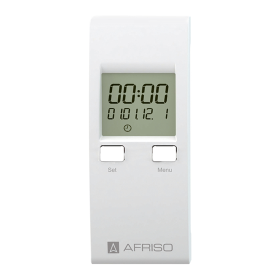
Betrieb Betrieb Anzeigeelemente A. Uhrzeit Stunde (Format: 24 h) B. Uhrzeit Minute C. Wochentag (1: Mo - 7: So) D. Anzeige Menü aktiv E. Schaltausgang Intervallfunktion aktiv F. Schaltausgang Pumpennachlauf aktiv G. Schaltkanal „Uhr2“ aktiv H. Schaltkanal „Uhr1“ aktiv I. Uhr-Modus aktiv J. - Page 14 Betrieb Bedienelemente Set-Taste: 1. Drücken Sie, bei aktiver Hauptan- zeige, die Set-Taste und wählen Sie den Betriebsmodus „Tag“, „Nacht oder „Uhr“ aus. 2. Drücken Sie, bei aktiver Hauptan- zeige, die Set-Taste lange* und wählen das Datum und Uhrzeit aus. 3. Bestätigen Sie mit der Set-Taste die eingestellten Werte.
- Page 15 Betrieb Hauptanzeige Die Hauptanzeige zeigt folgende Informationen an: • aktuelle Uhrzeit • aktuelles Datum • aktueller Wochentag • Betriebsmodus "Tag" , "Nacht" oder "Uhr" • Status der Schaltkanäle "Uhr1“ und "Uhr2“ im Betriebsmodus "Uhr" • Status der Schaltkanäle "Intervallfunktion“ und "Pumpennachlauffunk- tion“...
- Page 16 Betrieb Betriebsmodus einstellen Aus folgenden Betriebsmodi kann gewählt werden: • Tag-Modus (Heizungssteuerung ohne Temperaturabsenkung) • Nacht-Modus (Heizungssteuerung mit dauerhafter Temperaturabsenkung) • Uhr-Modus (Heizungssteuerung mit Temperaturabsenkung nach programmierten Schaltzeiten) • Kurzes Drücken der Set-Taste bei aktiver Hauptanzeige ändert den Betriebsmodus in der Reihenfolge Tag, Nacht, Uhr Abbildung 2: Navigationsstruktur Betriebsmodus Tag, Nacht, Uhr Uhrzeit und Datum einstellen 1.
- Page 17 Betrieb Menü Sie können im Menü folgende Parameter einstellen: • Schaltzeiten (t1 – t9) für Schaltkanäle „Uhr1“ und „Uhr2“ • Intervallzeitpunkt und Intervalldauer (Int) • Pumpennachlaufzeit (Pu) • Anlernfunktion für EnOcean®-Funk (BASE). Diese Funktion wird nur im Menü angezeigt, wenn das Produkt und ein Uhr-Funkmodul FM/FMA im Basismodul eingesetzt sind.
- Page 18 Betrieb 7.6.1 Schaltzeiten Temperaturabsenkung (t1 – t9) für die beiden Schaltkanäle „Uhr1“ und „Uhr2“ programmieren Es stehen 9 unabhängig programmierbare Speicherplätze für die beiden Schaltkanäle „Uhr1“ und „Uhr2“ zur Verfügung. Jeder Speicherplatz kann folgende Schaltdaten speichern: • Uhrzeit Beginn • Uhrzeit Ende •...
- Page 19 Betrieb Um einen Speicherplatz zu deaktivieren, müssen die Schaltkanäle „Uhr1“ und „Uhr2“ inaktiv sein. Das Symbol „Uhr“ (I) blinkt, wenn beide Schaltka- näle inaktiv sind. 7.6.2 Zuordnung der Schaltkanäle Die Reglermodule (Draht) werden wie folgt angesteuert: A. Schaltkanal „Uhr1“ B. Schaltkanal „Uhr2“ Die Reglermodule (Funk) werden wie folgt angesteuert: A.
- Page 20 Betrieb 7.6.3 Intervallfunktion programmieren Bei aktiver Intervallfunktion werden automatisch alle Regelkreise zyklisch eingeschaltet. Folgende Schaltdaten können programmiert werden: • Uhrzeit • Wochentag • Dauer des Intervalls - Um die Intervallfunktion zu deaktivieren, müssen Sie für die Dauer des Intervalls der Wert „0“ speichern. A.
- Page 21 Betrieb 7.6.4 Intervall einstellen 1. Drücken Sie die Menü-Taste mehrmals, bis die Anzeige der Intervall- funktion erscheint. 2. Drücken Sie die Set-Taste lange*. - Die Ziffern „Stunde“ blinken. 3. Drücken Sie die Menü-Taste, um den gewünschten Wert einzustellen. 4. Drücken Sie die Set-Taste, um den Wert zu bestätigen und abzuspei- chern.
- Page 22 Betrieb 7.6.5 Pumpennachlauffunktion programmieren Sie können für die Pumpennachlauffunktion eine Einschaltdauer von 0 –15 Minuten programmieren. Sie müssen zum Deaktivieren die Pum- pennachlauffunktion für die Einschaltdauer der Wert „0“ speichern. A. Anzeige „Menü Pumpennachlauf- funktion“ aktiv B. Einschaltdauer (0 - 15 Minuten) C.
- Page 23 Betrieb 7.6.6 Auf Werkseinstellungen zurücksetzen Die Werkseinstellungen können durch einen „Reset“ wiederhergestellt werden. Uhrzeit und Datum werden nicht zurückgesetzt. 1. Drücken Sie gleichzeitig für 10 Sekunden die Menü-Taste und Set-Taste. - In der Anzeige erscheint „Reset“. - Alle Werkseinstellungen sind wiederhergestellt. Parameter Funktion Standardwert...
-
Page 24: Wartung
Reihenfolge). 3. Entsorgen Sie das Produkt. Rücksendung Vor einer Rücksendung Ihres Produkts müssen Sie sich mit uns in Verbin- dung setzen. Gewährleistung Informationen zur Gewährleistung finden Sie in unseren Allgemeinen Geschäftsbedingungen im Internet unter www.afriso.com oder in Ihrem Kauf- vertrag. -
Page 25: Ersatzteile Und Zubehör
Ersatzteile und Zubehör Ersatzteile und Zubehör HINWEIS BESCHÄDIGUNG DURCH UNGEEIGNETE TEILE • Verwenden Sie nur Original Ersatz- und Zubehörteile des Herstellers. Nichtbeachtung dieser Anweisung kann zu Sachschäden führen. Produkt Artikelbezeichnung Art.-Nr. Abbildung Uhrmodul „UM“ 78113 Ersatzteile und Zubehör Artikelbezeichnung Art.-Nr. Abbildung Uhr-Funkmodul „FM“... -
Page 26: Timer Module
Operating instructions Timer module Product family CosiTherm® Type: UM Copyright 2015 AFRISO-EURO-INDEX GmbH. All rights reserved. Lindenstraße 20 74363 Güglingen Telefon+49 7135 102-0 Service+49 7135-102-211 Telefax +49 7135-102-147 info@afriso.com Version: 02.2016.0 www.afriso.com ID: 900.000.0711... - Page 27 About these operating instructions About these operating instructions These operating instructions describe the timer module (UM) (also referred to as "product" in these operating instructions). These operating instructions are part of the product. • You may only use the product if you have fully read and understood these operating instructions.
-
Page 28: Information On Safety
Information on safety Information on safety Safety messages and hazard categories These operating instructions contain safety messages to alert you to poten- tial hazards and risks. In addition to the instructions provided in these opera- ting instructions, you must comply with all directives, standards and safety regulations applicable at the installation site of the product. - Page 29 Information on safety Intended use CosiTherm® is a single room temperature controller used to control the tem- perature in rooms with underfloor heating system (heat/cool). The product is a part of CosiTherm® and may only be used to program the temperature reduction and the additional pump running time.
- Page 30 Information on safety Predictable incorrect application The product must never be used in the following cases and for the following purposes: • In conjunction with products which are used for health-saving or life- saving purposes or whose operation may incur hazards to humans, ani- mal or property.
-
Page 31: Transport And Storage
Transport and storage Transport and storage The product may be damaged as a result of improper transport or storage. NOTICE DAMAGE TO THE PRODUCT • Verify compliance with the specified ambient conditions during transport or storage of the product. • Use the original packaging when transporting the product. -
Page 32: Product Description
Product description Product description Overview of the individual CosiTherm® components Component Versions Explanation Base module Timer module Wireless module With internal antenna for timer module With external antenna Room tempera- Wire ture sensor Wireless, temperature Wireless, temperature and humidity Controller Wired with 2 control circuits module Wired with 6 control circuits... - Page 33 Product description Approvals, conformities, certifications The product complies with: • EMC Directive (2004/108/EC) Technical specifications Parameter Value General specifications Dimensions (W x H x D) 37 x 93 x 28 mm Weight 33 g Housing material Temperature reduction Functions Timing Date, time, weekday (leap year detection) Switching channels for temperature...
- Page 34 Product description Parameter Value Battery power > 3 months Output Electrical safety Degree of protection IP 30 (EN 60529) Electromagnetic compatibility (EMC) (2004/108/EC) Interference/immunity EN 61326-1: 2006-10 Timer module (UM)
- Page 35 Mounting Mounting Mounting the product 1. Remove the cover from the base module. 2. Plug the product into the slot of the base module. Timer module (UM)
-
Page 36: Electric Shock
Mounting Electrical connection DANGER ELECTRIC SHOCK • Verify that the degree of protection against electric shock (protection class II, double insulation) is not reduced by the type of electrical installation. Failure to follow these instructions will result in death or serious injury. DANGER ELECTRIC SHOCK CAUSED BY LIVE PARTS •... - Page 37 Commissioning Commissioning Commissioning the product For normal operation, the product must be inserted into the base module. For programming, you can remove the product from the base module. The inter- nal battery provides power for a period of approximately three months. For charging, you must insert the product into the base module.
-
Page 38: Operation
Operation Operation Display elements A. Time hours (format: 24 h) B. Time minutes C. Weekday (1: Mo - 7: Su) D. Menu active indicator E. Switching output Interval function active F. Switching output Additional Pump Running Time active G. Switching channel "Timer2" active H. - Page 39 Operation Controls Set key 1. When the main screen is active, press the Set key to select the operating mode "Day", "Night" or "Timer". 2. When the main screen is active, hold down* the Menu key to select date and time. 3.
- Page 40 Operation Main screen The main screen of the timer module shows the following information: • Current time • Current day • Current weekday • Operating mode "Day" , "Night" or "Timer" • Status of switching channels "Timer1“ and "Timer2“ in operating mode "Timer"...
- Page 41 Operation Setting the operating mode The following operating modes are available: • Day mode (heating control without temperature reduction) • Night mode (heating control with permanent temperature reduction) • Timer mode (heating control with temperature reduction according to programmed switching times) •...
- Page 42 Operation Menu The following parameters can be set via the menu: • Switching times (t1 – t9) for switching channels "Timer1" and "Timer2" • Interval point in time and interval duration (Int) • Additional Pump Running Time (Pu) • Teach-in function for EnOcean® wireless (BASE). This function is only available if the product and a wireless module for the timer module FM/ FMA are plugged into the base module.
- Page 43 Operation 7.6.1 Programming the switching times for temperature reduction (t1 – t9) for the two switching channels "Timer1" and "Timer2" The system provides 9 independently programmable memory blocks for the two switching channels "Timer1" and "Timer2". Each memory block can hold the following switching data: •...
- Page 44 Operation To disable a memory block, the switching channels "Timer1" and "Timer2" must be inactive. The symbol "Timer" (I) flashes when both switching channels are inactive. 7.6.2 Assignment of the switching channels The controller modules (wired) are controlled as shown below: A.
- Page 45 Operation 7.6.3 Programming the Interval function If the Interval function is active, all control circuits are switched on cycli- cally. The following switching data can be programmed: • Time • Weekday • Duration of interval - To disable the Interval function, you must set the duration of the inter- val to "0".
- Page 46 Operation 7.6.4 Setting the interval 1. Keep pressing the Menu key until the Interval function screen is dis- played. 2. Hold down* the Set key. - The "Hour" digits flash. 3. Press the Menu key to adjust the required value. 4.
- Page 47 Operation 7.6.5 Programming the Additional Pump Running Time function You can program an additional pump running time from 0 to 15 minutes. To disable the Additional Pump Running Time function, you must set the duration "0". A. Indicator "Menu Additional Pump Running Time Function"...
- Page 48 Operation 7.6.6 Restoring the factory settings A "Reset" restores the factory settings. Time and date are not reset. 1. Hold down the Menu key and the Set key simultaneously for 10 seconds. - The display shows "Reset". - The factory defaults are restored. Parameter Function Default value...
-
Page 49: Maintenance
2. Dismount the product (see chapter "Mounting", reverse sequence of steps). 3. Dispose of the product. Returning the device Get in touch with us before returning your product. Warranty See our terms and conditions at www.afriso.com or your purchase contract for information on warranty. Timer module (UM) -
Page 50: Spare Parts And Accessories
Spare parts and accessories Spare parts and accessories NOTICE DAMAGE DUE TO UNSUITABLE PARTS • Only use genuine spare parts and accessories provided by the manufactu- rer. Failure to follow these instructions can result in equipment damage. Product Product designation Part no. -
Page 51: Instrukcja Eksploatacji
Instrukcja eksploatacji Moduł czasowy System CosiTherm® Typ: UM Copyright 2015 AFRISO-EURO-INDEX GmbH. Wszystkie prawa zastrzeżone. Lindenstraße 20 74363 Güglingen telefon +49 7135-102-0 serwis +49 7135-102-211 telefaks +49 7135-102-147 info@afriso.com Wersja: 02.2016.0 www.afriso.com ID: 900 000.0711... - Page 52 Objaśnienia do niniejszej instrukcji eksploatacji Objaśnienia do niniejszej instrukcji eksploatacji Niniejsza instrukcja eksploatacji opisuje moduł czasowy (UM) (poniżej zwany także „produktem“). Niniejsza instrukcja eksploatacji jest częścią produktu. • Produkt wolno użytkować dopiero po całkowitym przeczytaniu i pełnym zrozumieniu instrukcji eksploatacji. •...
- Page 53 Informacje na temat bezpieczeństwa Informacje na temat bezpieczeństwa Wskazówki ostrzegawcze i klasy zagrożenia Niniejsza instrukcja eksploatacji zawiera wskazówki ostrzegawcze zwraca- jące uwagę na potencjalne zagrożenia oraz ryzyka. Poza zaleceniami zawar- tymi w niniejszej instrukcji eksploatacji trzeba przestrzegać wszystkich warunków, norm oraz przepisów bezpieczeństwa obowiązujących w miej- scu użytkowania produktu.
-
Page 54: Informacje Na Temat Bezpieczeństwa
Informacje na temat bezpieczeństwa Ten symbol ostrzega przed niebezpiecznym napięciem elektrycznym. O ile symbol ten pojawia się we wskazówce ostrzegawczej, zachodzi niebezpieczeństwo porażenia prądem elektrycznym. Stosowanie zgodne z przeznaczeniem System CosiTherm® jest to regulator temperatury pokojowej służący do regulacji temperatury w pomieszczeniach z ogrzewaniem podłogowym (grzanie / chłodzenie). - Page 55 Informacje na temat bezpieczeństwa Przewidywalne błędne stosowanie Produktu nie wolno stosować w szczególności w następujących przypad- kach i do następujących celów: • w powiązaniu z produktami, które służą bezpośrednio lub pośrednio do celów związanych z zabezpieczeniem zdrowia lub życia człowieka albo których eksploatacja może powodować...
- Page 56 Transport i składowanie Transport i składowanie Niewłaściwy transport i składowanie mogą spowodować uszkodzenie pro- duktu. WSKAZÓWKA USZKODZENIE PRODUKTU • Należy upewnić się, że podczas transportu i składowania produktu dotrzy- mywane są warunki otoczenia wyszczególnione w specyfikacji. • Do celów transportowych należy wykorzystywać oryginalne opakowanie. •...
-
Page 57: Opis Produktu
Opis produktu Opis produktu Przegląd poszczególnych części składowych systemu CosiTherm® Komponent Warianty Objaśnienie moduł podsta- wowy moduł czasowy nadajnik radiowy z anteną wewnętrzną modułu czaso- z anteną zewnętrzną wego czujnik pokojowy D przewodowy bezprzewodowy, temperatura bezprzewodowy, temperatura i wil- gotność moduł... - Page 58 Opis produktu Działanie System CosiTherm® jest to regulator temperatury pokojowej służący do regulacji temperatury w pomieszczeniach z ogrzewaniem podłogowym (grzanie / chłodzenie). Niniejszy produkt jest częścią systemu CosiTherm®. Produkt jest wyposażony w stuletni kalendarz. Na wyświetlaczu przedstawi- ana jest data, czas i dzień tygodnia. Produkt posiada 2 niezależnie progra- mowalne kanały sterujące służące do obniżania temperatury.
- Page 59 Opis produktu Dopuszczenia, certyfikaty, deklaracje Produkt jest zgodny z: • dyrektywą unijną dotyczącą kompatybilności elektromagnetycznej (2004/108/WE). Dane techniczne Parametr Wartość Dane ogólne wymiary z izolacją 37 x 93 x 28 mm (szerokość x wysokość x głębokoś ć) waga 33 g materiał...
- Page 60 Opis produktu Parametr Wartość składowanie -10/+60 °C maksymalna wilgotność powietrza bez kondensacji Zasilanie napięcie znamionowe DC 3,3 V, przez moduł podstawowy moc nominalna 3 mW sprawność baterii > 3 miesięcy wyjście Bezpieczeństwo elektryczne stopień ochrony IP 30 (EN 60529) Kompatybilność elektromagnetyczna (EMC) (2004/108/WE) emisja zakłóceń...
- Page 61 Montaż Montaż Montaż produktu 1. Usunąć osłonę z modułu podsta- wowego. 2. Wsunąć produkt do gniazda wty- kowego modułu podstawowego. Moduł czasowy (UM)
- Page 62 Montaż Przyłącze elektryczne NIEBEZPIECZEŃSTWO PORAŻENIE PRĄDEM ELEKTRYCZNYM • Należy upewnić się, że rodzaj instalacji elektrycznej nie zmniejsza zakresu ochrony przed porażeniem prądem elektrycznym (klasa ochronności, izo- lacja ochronna). Nieprzestrzeganie niniejszych zaleceń prowadzi do śmierci lub poważnych obrażeń. NIEBEZPIECZEŃSTWO PORAŻENIE PRĄDEM ELEKTRYCZNYM PRZEZ ELEMENTY ZNAJDU- JĄCE SIĘ...
- Page 63 Uruchomienie Uruchomienie Uruchamianie produktu W celu eksploatacji produkt należy zainstalować w module podstawowym. W celu zaprogramowania produkt można wyjąć z modułu podstawowego. Wewnętrzna bateria modułu jest w staniepodtrzymać zasilanie przez okres około trzech miesięcy. W celu podładowania baterii produkt musi zostać zainstalowany w module podstawowym.
- Page 64 Eksploatacja Eksploatacja Elementy ekranu A. czas - godzina (format: 24 h) B. czas - minuty C. dzień tygodnia (1: poniedziałek - 7: niedziela) D. aktywny obraz menu E. aktywne wyjście sterujące funkcji włączania czasowego obwodów F. aktywne wyjście sterujące czasu opóźnienia wyłączania pompy G.
- Page 65 Eksploatacja Elementy obsługi Przycisk Set: 1. Na aktywnym obrazie podsta- wowym wcisnąć przycisk Set i wybrać program „dzienny”, „nocny”lub „czasowy”. 2. Na aktywnym obrazie podsta- wowym dłużej* wcisnąć przycisk Set i wybrać datę oraz czas. 3. Ustawione wartości potwierdzić przyciskiem Set. Przycisk Menu 4.
- Page 66 Eksploatacja Obraz podstawowy Obraz podstawowy zawiera następujące informacje: • aktualny czas, • aktualną datę, • aktualny dzień tygodnia, • program "dzienny" , "nocny" lub "czasowy", • stan kanałów sterujących "zegar1“ oraz "zegar2“ w programie "czasowym", • stan kanałów sterujących "funkcja włączania czasowego obwodów“ oraz "funkcja opóźnienia wyłączania pompy“.
- Page 67 Eksploatacja Ustawianie trybu pracy Można wybrać następujące tryby pracy: • program dzienny (regulacja ogrzewania bez obniżania temperatury), • program nocny (regulacja ogrzewania z trwałym obniżaniem temperatury), • program czasowy (regulacja ogrzewania z obniżaniem temperatury według zaprogramowa- nych czasów sterowania). • Krótkie wciśnięcie przycisku Set na aktywnym obrazie podstawowym zmienia tryb pracy w kolejności: program dzienny, nocny, czasowy.
- Page 68 Eksploatacja Ustawianie czasu i daty 1. Wcisnąć i przytrzymać dłużej* przycisk Set. - Cyfry pola „godzina” migaj?. 2. Wcisnąć przycisk Menu w celu ustawienia pożądanej wartości. 3. Wcisnąć przycisk Set w celu potwierdzenia wartości i wprowadzenia jej do pamięci układu. - Cyfry pola „minuta”...
- Page 69 Eksploatacja Menu W menu można ustawić następujące parametry: • czasy sterowania (t1 – t9) dla kanałów sterujących „zegar1“ oraz „zegar2“, • moment i okres włączania obwodów (Int), • czas opóźnienia włączania pompy (Pu), • funkcję programowania systemu bezprzewodowego EnOcean® (BASE). Ta funkcja jest wyświetlana w menu tylko wtedy, gdy w module podsta- wowym jest zainstalowany niniejszy produkt oraz nadajnik radiowy modułu czasowego FM/FMA.
- Page 70 Eksploatacja 7.6.1 Programowanie okresów obniżania temperatury (t1 – t9) dla obu kanałów sterujących „zegar1“ oraz „zegar2“ Do dyspozycji jest 9 niezależnie programowalnych miejsc w pamięci układu dla obu kanałów sterujących „zegar1“ oraz „zegar2“. Na każdym miejscu w pamięci układu można zapisać nastepujące dane: •...
- Page 71 Eksploatacja W celu dezaktywacji miejsca w pamięci układu kanały sterujące „zegar1“ oraz „zegar2“ muszą być nieaktywne. Symbol „zegar“ (7) miga, gdy oba kanały sterujące są nieaktywne. Moduł czasowy (UM)
- Page 72 Eksploatacja 7.6.2 Przyporządkowanie kanałów sterujących Regulacja modułów sterujących D odbywa się w następujący sposób: A. kanał sterujący „zegar1“ B. kanał sterujący „zegar2“ Abbildung 7: Układ kanałów modułu sterującego D Regulacja modułów sterujących F odbywa się w następujący sposób: A. kanał sterujący „zegar1“ Abbildung 8: Układ kanałów modułu sterującego F W przypadku modułów sterujących F kanał...
- Page 73 Eksploatacja 7.6.3 Programowanie funkcji włączania czasowego obwodów W przypadku aktywnej funkcji włączania czasowego obwodów wszyst- kie obwody regulacji włączają się okresowo automatycznie. Można zaprogramować następujące parametry sterujące: • czas, • dzień tygodnia, • przedział czasowy. - W celu dezaktywacji funkcji włączania czasowego obwodów trzeba wprowadzić...
- Page 74 Eksploatacja 7.6.4 Ustawianie czasowego włączania obwodów 1. Kilkakrotnie wcisnąć przycisk Menu aż do włączenia się obrazu funkcji włączania czasowego obwodów. 2. Dłużej* wcisnąć przycisk Set. - Cyfry pola „godzina” migają. 3. Wcisnąć przycisk Menu w celu ustawienia pożądanej wartości. 4. Wcisnąć przycisk Set w celu potwierdzenia wartości i wprowadzenia jej do pamięci układu.
- Page 75 Eksploatacja 7.6.5 Programowanie funkcji opóźnienia wyłączania pompy Dla funkcji opóźnienia wyłączania pompy można zaprogramować okres włączenia wynoszący 0 – 15 minut. W celu dezaktywacji funkcji opóźni- enia wyłączania pompy trzeba wprowadzić do pamięci układu wartość okresu włączenia równą „0“. A. aktywny obraz „menu funkcji opóźnienia wyłączania pompy“...
- Page 76 Eksploatacja 7.6.6 Przywracanie ustawień fabrycznych Ustawienia fabryczne mogą zostać przywrócone przez wykonanie funk- cji „Reset”. Czas i data pozostają bez zmian. 1. Nacisnąć jednocześnie przyciski Menu oraz Set przez okres 10 sekund. - Na wyświetlaczu pojawia się komunikat „Reset”. - Wszystkie ustawienia fabryczne zostały przywrócone. Parametr Funkcja Wartość...
- Page 77 Eksploatacja Parametr Funkcja Wartość standar- dowa T-3 do t-9 czas rozpoczęcia godzina 0.00 czas zakończenia godzina 0.00 dzień (tygodnia) roz- poczęcia dzień (tygodnia) zakończenia kanał sterujący nieaktywny „zegar1“ kanał sterujący nieaktywny „zegar2“ funkcja włączania czaso- czas godzina 1.00 wego obwodów przedział...
- Page 78 2. Wykonać demontaż produktu (patrz rozdział Montaż w odwrotnej kolejności). 3. Produkt poddać utylizacji. Zwrot Przed zwrotną wysyłką produktu wymagany jest kontakt z producentem. Gwarancja Informacje dotyczące gwarancji są dostępne w naszych Ogólnych Warunkach Handlowych w internecie pod adresem www.afriso.com lub w umowie kupna. Moduł czasowy (UM)
- Page 79 Części zamienne i wyposażenie dodatkowe Części zamienne i wyposażenie dodatkowe WSKAZÓWKA USZKODZENIE SPOWODOWANE PRZEZ STOSOWANIE NIEWŁAŚCI- WYCH CZĘŚCI • Należy stosować wyłącznie oryginalne części zamienne i wyposażenie dodatkowe producenta. Nieprzestrzeganie niniejszego zalecenia może doprowadzić do powstania szkód materialnych. Produkt Nazwa artykułu Numer artykułu Ilustracja moduł...
Need help?
Do you have a question about the CosiTherm UM and is the answer not in the manual?
Questions and answers