Table of Contents
Advertisement
Quick Links
Advertisement
Table of Contents

Related Manuals for Seica PILOT H4


Summary of Contents for Seica PILOT H4
- Page 3 PILOT H4 OPERATOR MANUAL...
- Page 4 The material in this manual is for informational purposes only, and is subject to change without notice. Seica S.p.A. assumes no liability in case of error or consequential damages that may result from the use or misinterpretation of any of the procedures provided in this publication.
-
Page 5: Table Of Contents
contents CONTENTS 1 GENERAL ...................................... 1-1 1.1 A ....................................1-2 UDIENCE 1.2 A ..................................... 1-2 SSUMPTIONS 1.3 S ................................1-2 YNTAX ONVENTIONS 1.4 S ..............................1-4 EICA USTOMER ENTER 1.5 C ........................... 1-4 OMMENTS ABOUT THE DOCUMENTATION ... - Page 6 Fig. 2-1 PILOT H4: System overview ..................2-1 Fig. 2-2 PILOT H4: System synoptics ..................2-2 Fig. 3-1 PILOT H4: Run Page of the VIVA software ............... 3-6 Fig. 3-2 PILOT H4: Program Report dialog window ................ 3-8 ...
-
Page 7: General
general 1 GENERAL The PILOTH4 system belongs to the new generation of flying probers, created to solve the problem of testing electronic boards without the aid of fixtures or specialized mechanical devices. PILOTH4 is particularly suitable for testing prototypes, samples, small series, SMD boards with specific accessibility problems: in general, when the costs and time of constructing a fixture are not justifiable. -
Page 8: Audience
PILOT H4 - Operator Manual 1.1 AUDIENCE This manual contains useful information for: • Operators in charge of testing mounted boards • Developers of test programs • Technicians in charge of maintenance operations on the system 1.2 ASSUMPTIONS Technical knowledge on testing, electronics and use of Personal Computer is required. -
Page 9: Fig. 1-1 Pilot H4: "System Configuration" Dialog Window
Graphical User Interface of the VIVA software provides a set of commands and buttons, arranged in horizontal and vertical toolbars. Fig. 1-2 is an example of the VIVA software GUI. Fig. 1-2 PILOT H4: Example of VIVA Software GUI... -
Page 10: Seica Customer Care Center
PILOT H4 - Operator Manual 1.4 SEICA CUSTOMER CARE CENTER SEICA “CUSTOMER CARE CENTER” (SCCC) is the support to the customers. It is always possible to call the SCCC if you can’t solve your problem through the product help on line or technical documentation. -
Page 11: Safety Recommendations
1.7 SAFETY RECOMMENDATIONS 1.7.1 Project criteria The system PILOT H4 has been designed and manufactured in accordance with the essential safety 2006/42/CE; in the 2004/108/EC requirements contained in the Machine Directive EMC DIRECTIVE (and subsequent amendments) on electromagnetic compatibility; in the Low Voltage Directive 2006/95/CE (and subsequent amendments) on electric safety. -
Page 12: Safety Devices Location
PILOT H4 - Operator Manual 1.7.3 Safety devices location Fig. 1-3 PILOT H4: Safety device location... -
Page 13: Warnings And Recommended Behavior
In order to avoid all risks of injury to persons or damage to the machines installed, it is recommended to follow the warnings and rules of behavior: Note: Seica declines all liability for any damage to things and/or injury to persons deriving from failure to follow these warnings. -
Page 14: Intended Use
There is the risk of pricking the finger if a careless work is done when replacing the test needle. 1.7.8 WARNINGS FOR MAINTENANCE ACTIVITIES The complexity and the high technological level of the PILOT H4 test system, require a detailed description and classification of the maintenance schedule, as well as the requirements for the personnel authorized to perform these activities. -
Page 15: Technical Specifications
general 1.8 TECHNICAL SPECIFICATIONS To ensure a correct operation of the system, it is necessary to verify that the requirements described here below are met. 1.8.1 Operating environment The system should be installed in a relatively dry, clean environment, preferably with an air conditioning system, which maintains a constant temperature and humidity. -
Page 16: Air Specifications
PILOT H4 - Operator Manual 1.8.3 Air specifications Filtered at 3 μm Air supply: 99.9% of the oil must be filtered from air The air must be dried with a dew point of 10 °Celsius Compressed air supply: Typical: 4 Atm Max: 6 Atm Air supply setting: Min. -
Page 17: Overall Dimensions
The following is a scale drawing of the required work area and the place usually occupied by the operator. Fig. 1-4 PILOT H4: System layout Fig. 1-5 PILOT H4: Side view and front view 1-11... -
Page 18: Work Area
The figures 1-4- and 1-5 respectively, show the system layout and the work area with overall dimensions Fig. 1-6 PILOT H4: Work area Height 1480mm (58.27”) Length 1740mm (68.50”) -
Page 19: System Overview
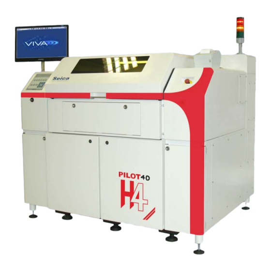
2 SYSTEM OVERVIEW Fig. 2-1 PILOT H4: System overview B1 - Front doors for easy access to all the systems electronic racks and components B2 - Side panel B3 - Protective cover (tiltable), protecting the work area B4 -... -
Page 20: General Architecture
2.1 GENERAL ARCHITECTURE The system can be considered as a whole with functional blocks interacting together. The picture below illustrates the system general architecture. What follows is a technical description for every block. CONS22 Fig. 2-2 PILOT H4: System synoptics... -
Page 21: Ac Group
system overview 2.1.1 AC group The AC Group provides the AC supply voltages to the entire system through a Main Transformer included within the AC Group itself. It is located under the right rear door as illustrated in the following figure. F1 –... -
Page 22: Ate Rack
PILOT H4 - Operator Manual 2.1.2 ATE rack Located under the left front door, it is composed of electronic modules that are required for the system measurements. 2.1.3 Axis drivers and filters Located under the rear left door of the system there are the axis drivers and filters. They control the head movements along the X,Y and Z axis generating the proper signals to drive the axis motors. - Page 23 system overview The section here below provides a description of the control panel: BUTTON DESCRIPTION LIGHT Switches the main MAIN ON = ON MAIN ON electronics ON MAIN OFF = OFF Switches the main MAIN ON = OFF MAIN OFF electronics OFF MAIN OFF = OFF BUTTON...
- Page 24 PILOT H4 - Operator Manual DESCRIPTION It moves the camera along the JOYSTICK XY axes BUTTON DESCRIPTION It immediately stops the system (it stops any movements of axes EMERGENCY and probes), switching OFF the power. The Personal Computer remains ON...
-
Page 25: Cover
system overview 2.1.5 Cover Protective cover (tiltable) with plexiglass window. 2.1.6 Power supplies Several power supplies provide voltages both to the system and the Unit Under Test (herein after: UUT). 2.1.7 Motors Brushless and stepper motors drive probes along X,Y and Z axes. 2.1.8 Light indicator or semaphore These device signal the system operating conditions as illustrated below. -
Page 26: Test Area
PILOT H4 - Operator Manual 2.1.10 Test area The test area is a (530 x 400mm) area where the UUT is loaded for the test. In the work area there are the four measuring probe heads, the accessory box, the board handler and the movable plate. -
Page 27: Getting Started
board testing 3 GETTING STARTED Before staring to test a board it is a good rule to check some parameters and setting in order to obtain the desired result. In this chapter there are all operations necessary to start the test activity together with the description of all parameters present in the different dialogs that appear on the screen. -
Page 28: System Starting
PILOT H4 - Operator Manual 3.1 SYSTEM STARTING Open the air tap located on the rear side of the system. Set the MAIN-SWITCH on the rear side of the system to “1”. Press the button MAIN ON on the control panel (the light indicator of the button will turn ON) -
Page 29: Translation
board testing 3.2 TRANSLATION To test the board in a correct way it is very important to perform a correct translation and marker setting. The translation procedure is used to reference the board coordinates to the test system and it is executed by the operator on the first board. - Page 30 PILOT H4 - Operator Manual 2. Press the The system will display window Translation. The translation procedure is the alignment of the board reference system to the test system. In this way the test system acquires the position of the board to be tested and use it as a common reference.
- Page 31 board testing Position the mouse pointer on the point that has to be reached, then press the right button of the mouse. The cross will reach the position indicated by the point of the arrow before the pressing of the right button of the mouse. 4.
-
Page 32: Test Program Execution
1. If not already opened, press the button to enter the Wizard Environment. The following dialog windows is displayed Fig. 3-1 PILOT H4: Run Page of the VIVA software Once you are in the “Run page”, press the button to start the test program. - Page 33 board testing Other buttons available in the Run page toolbar are as follows (in brackets is reported the corresponding command from keyboard: Start Program (Spacebar) To start the test program for the selected board. Stop Program (Esc) To stop the test program for the selected board. Failed Step Only To display a list showing the program executions..
-
Page 34: Test Results
3.4 TEST RESULTS When the test program execution is completed, the following dialog window is displayed to show the test results: Fig. 3-2 PILOT H4: Program Report dialog window Press the button to save the test report. Press the button... -
Page 35: System Shutdown
board testing 3.5 SYSTEM SHUTDOWN 1. Press the button on the control panel (the light indicator of the button will turn OFF) 2. Press the button on the control panel (the light indicator of the button will turn OFF) 3. Press the button on the control panel (the light indicator of the button will turn OFF) 4. -
Page 36: Fixed Probes
PILOT H4 - Operator Manual 3.6 FIXED PROBES Fixed probes increase the available number of test channels in the test area. The fixed channel can be connected to a channel card or to a user power supply. In this way the channel or power supply voltage is connected to the unit under test. -
Page 37: Supports
board testing 3.7 SUPPORTS Supports prevents the board from bending during test especially when the board is not rigid enough. They are similar to a fixed probe but they do not have a needle or a connection cable. For support positioning, refer to similar instruction above used to position the fixed probe. -
Page 39: Maintenance Operations
4 MAINTENANCE OPERATIONS This section illustrates the inspection and maintenance operations for the PILOT H4 test system. The following table summarizes the inspection and maintenance operations. Operation To be performed... General inspection of the system and cleaning of... -
Page 40: General Inspection And Cleaning
PILOT H4 - Operator Manual 4.1 GENERAL INSPECTION AND CLEANING Inspect the cleanliness of the system daily. Press buttons to work under safety conditions. Only then open the protective cover and remove any traces of dust or dirt using a small aspirator (do not use a compressed air blower to avoid blowing impurities into inaccessible parts) or a clear brush if necessary. -
Page 41: Diagnostic Tools
maintenance operations 4.3 DIAGNOSTIC TOOLS The system has three diagnostic programs: 1. System diagnostic 2. DMC Manager (Diagnostic Mechanical Check) 3. OVP (Operation Verification Program) 4.3.1 System diagnostic It is possible to check the system functionality with the system diagnostic. To run the diagnostic, from the VIVA main window, press the button to enter the Wizard Environment. -
Page 42: Meaning Of The Error Messages
PILOT H4 - Operator Manual Joystick: this field enables the user to check the operation of the joystick (option). Start & Stop: this field enables the user to check the operation of the START and STOP buttons. Probes: this field enables the user to check the motion of the four mobile probes along the axis Z. -
Page 43: Tab. 4-2: Table Of Corrective Actions
MODULE ERROR SOLUTION ACLAM Contact Seica's Customer Service % SH LN 1 CH n (p/s) Replace the faulty relay on line 1. % SH LN 2/3 CH n (p/s) Replace the faulty relay on lines 2 and/or 3. -
Page 44: Scafp Board Layout
PILOT H4 - Operator Manual SCAFP board layout Fig. 4-1 PILOT H4: SCAFP Module layout... -
Page 45: F32/P32 Board Layout
F32/P32 board layout Fig. 4-2 PILOT H4: F32/P32 Module layout... -
Page 46: S64 Board Layout
PILOT H4 - Operator Manual S64 board layout Fig. 4-3 PILOT H4: S64 Module layout... -
Page 47: Ovp
Before performing a test with OVP program, it is advisable to carry out an automatic translation using channels 124 (TP61-1) and 61 (TP108-1). If the result of the test is FAIL, contact the your nearest Seica support office for further information. Fig. 4-4 PILOT H4: OVP board... -
Page 48: Replacing The Probe Needle
PILOT H4 - Operator Manual 4.4 REPLACING THE PROBE NEEDLE The probe needle will wear in time, so it must be replaced. We recommend you proceed as follows: 1). Press buttons in order to work under safety conditions. 2). Hold cable (1) with hands and disconnect it from the probe support 3). - Page 49 maintenance operations 1). Press buttons in order to work under safety conditions. 2). Remove the internal socket head screws (1) using a 2mm Allen wrench and remove also the cover 3). Loose the screws (2) 4). 4). Loose the screws (3) with an Allen wrench and move downwards the cable guide 5).
-
Page 50: Calibrations
PILOT H4 - Operator Manual 4.6 CALIBRATIONS All the probes, as well as all the moving parts installed on the heads of a Flying Prober, should be occasionally calibrated when the part is replaced, and periodically, in order to guarantee the best performance. -
Page 51: Fig. 4-5 Pilot H4: "System Maintenance" Dialog Window, Tab "Calibration
Fig. 4-5 PILOT H4: “System Maintenance” dialog window, tab “Calibration” 4-13... -
Page 52: Fig. 4-6 Pilot H4: "System Configuration" Dialog Window, Tab "Calibration
PILOT H4 - Operator Manual The tab Calibrations of the System Configuration Environment will open. Fig. 4-6 PILOT H4: “System Configuration” dialog window, tab “Calibration” Here the operator may select all the options to calibrate the electrical probes and launch the... -
Page 53: Joystick Calibration
2 – Press “Calibrate” N.B. DO NOT move the joystick during this procedure. 4.6.2 CAMERA CALIBRATION It is not necessary for the operator to execute this calibration. It is performed by Seica before delivering the system. 4.6.3 ELECTRICAL PROBES CALIBRATION This procedure allows to automatically calibrate the measuring probes as compared to XY-Z axes. -
Page 54: Fig. 4-8 Pilot H4 Setting The Electrical Probe Calibration
In the System Configuration dialog, select items: “Probes”; “Z Alignment” and “X and Y Alignment” (See fig.3-10): Fig. 4-8 PILOT H4 Setting the Electrical Probe Calibration Set the value of field “Check Board Set Area Number” to 2 Select “Probe type” as shown in the picture... - Page 55 maintenance operations Press the button for each electrical probe installed (Here: 1 and 3” and press Follow the instructions on screen and press YES to continue Follow the instructions on screen and press YES to continue 4-17...
- Page 56 PILOT H4 - Operator Manual Check if the position of the probe 1 is over the central round probing area check-board press . Skip the next picture to continue. Press if the probe is not in that area and go on the next picture.
- Page 57 Press the button for higher accuracy Fig. 4-9 PILOT H4 “Set Camera X (TOP) dialog window Now adjust the X alignment of the Top camera with the arrow keys Press to continue 4-19...
- Page 58 Another dialog will be displayed to perform the Y alignment of the Top camera. Press the button for higher accuracy Fig. 4-10 PILOT H4 “Set Camera Y (TOP) dialog window” Now adjust the Y alignment of the Top camera with the arrow keys Press...
- Page 59 Align the Top Camera and the Bottom camera on the same hole on the Check Board. Use the arrow keys to center the view-finder on the hole for the Top camera Fig. 4-11 PILOT H4 Align top camera Press to continue...
-
Page 60: Mobile Capacitive Probe Calibration
4.6.4 MOBILE CAPACITIVE PROBE CALIBRATION In the dialog “System Configuration” select the checkbox “Mobile Opens Probe CPM”, then press Fig. 4-12 PILOT H4 Setting the “Mobile Opens Probe” Calibration” Follow the instructions on screen and press YES to continue when done. -
Page 61: Fig. 4-13 Pilot H4 "Calibration Mobile Open Probe" Dialog Window
Follow the instructions and press YES to continue when done. In the dialog “Calibration Mobile Open Probe” press the button to zoom in for more accuracy Fig. 4-13 PILOT H4 “Calibration Mobile Open Probe” dialog window 4-23... - Page 62 PILOT H4 - Operator Manual Use the arrow keys to adjust the alignment of the red circle over the top of the capacitive probe Press to save the new X,Y position Repeat the same steps to align the bottom side of the capacitive probe and press to save the new X,Y position.
-
Page 63: Stamper Calibration
4.6.5 STAMPER CALIBRATION In the System Configuration dialog, select the checkbox “Stamper” (See fig. 3-19) and press Fig. 4-14 PILOT H4 Setting the “Stamper” Calibration” 4-25... - Page 64 PILOT H4 - Operator Manual Follow the instructions and press YES to continue Follow the instructions and press YES to continue In the dialog displayed, press the button to zoom out and enlarge the view to search the mark, if it is not displayed...
- Page 65 maintenance operations Center the mark with the red circle using the joystick or the arrow keys Press to save the new calibration 4-27...
-
Page 66: Lubricating The Ball Screws
PILOT H4 - Operator Manual 4.7 LUBRICATING THE BALL SCREWS We recommend lubricating the ball screws with a small quantity of grease (for high speed movements) every 500-600 hours. Apply a little grease by hand, spreading it uniformly on the ball screws. The ball screws layout is shown in the figure below. -
Page 67: Appendix
5 APPENDIX PILOT H4 system has been designed and manufactured in accordance with the main safety European requirements. Each system has got an identification label with a logo that certifies the compliance with these directives. The figure below shows an example of the abovementioned label. -
Page 68: Use The Hdu Recovery Utility
Before performing any HDU replacement on the PC, ensure the part is replaced with an equivalent part as OEM. Seica S.p.A. declines any liability for data loss caused by the fault to comply with the instructions included in this section.
Need help?
Do you have a question about the PILOT H4 and is the answer not in the manual?
Questions and answers