
Related Manuals for SoundEar SoundEar 3 Series


Summary of Contents for SoundEar SoundEar 3 Series
- Page 1 ound ® MANUAL – UK MODEL 300 MODEL 300 MODEL 310 MODEL 310 MODEL 320 MODEL 320...
-
Page 2: Table Of Contents
TABLE OF CONTENTS Congratulations on your new soundear®3 Box Contents Before you start SoundEar®3 model 300 and 310 SoundEar®3 model 320 Mounting SoundEar®3 on wall · Model 300 or model 310 · Model 320 Set time Formatting the USB key... -
Page 3: Congratulations On Your New Soundear®3
This instruction manual provides information on how to take advantage of your product to the fullest. In order to fully understand the features and possibilities of SoundEar®3, we advice you to read this manual carefully before you start using your SoundEar®3. -
Page 4: Box Contents
BOx CONTENTS Check package contents depending on the package purchased. SoundEar®3 USB key with software External microphone 4 pole extension cable for calibration Power adaptor with EU, US og UK plug USB adaptor cable (A-plug or micro-B) R e t u R n t o ta b l e o f C o n t e n t s... -
Page 5: Before You Start
BEFOrE yOU STArT SOUNDEAr®3 – MODEL 300 AND 310 SoundBuster USB Log/ Power Ext. mic. 5 VDC/ config. PC data Power Analogue 0-10V/ 24 VDC Outputs 4-20 mA 24 VDC/150 mA Analog output Export data Micro USB to SoundBuster Microphone... -
Page 6: Soundear®3 Model 320
SOUNDEAr®3 – MODEL 320 Ext. mic. Power USB Log/ SoundBuster 5 VDC/ config. PC data Analogue 0-10V/ Power Outputs 4-20 mA 24 VDC 24 VDC/150 mA Microphone input. SoundBuster is Micro USB to Export data Analog output for a relay used for... -
Page 7: Mounting Soundear®3 On Wall
320 Loosen the screw to remove the wall mount. Fasten the wall mount to the wall with 4 screws. Hang SoundEar®3-320 onto the wall mount and fasten it with the screw. SET TIME SoundEar®3 has a built-in time and date function that will set automatically when you connect the device to your PC. -
Page 8: Formatting The Usb Key
FOrMATTINg THE USB KEy the usB key included is formatted in the format called ”fat32”. If you wish to use an alternative USB key with a larger memory, it is important that it has the same format. Please follow the steps below to format your USB key. note! remember to export any files you may have on your USB key before formatting, as the formatting will... -
Page 9: Touch Display
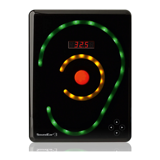
TOUCH DISPLAy located on the front of soundear®3 you will find a touch display from which you can control the device manually. The functions of the touch display include setting alarm levels, time, noise level, temperature, Leq15 and on/off function for the mini display. - Page 10 the alarm level. Hold your finger down until the desired alrarm level is reached. example: If the alarm is set to 80 dB, the red light will be lit when the noise level reaches 80 dB. As a standard set- ting, the yellow light will be lit 5 dB before the alarm level is reached, in this case at 75 dB.
-
Page 11: Software Installation
If the pop-up window does not appear, please find the installa- tion programme on the USB drive. Double-click on the SoundEar®3 installation programme to begin the software installation. R e t u R n t o ta b l e o f C o n t e n t s... -
Page 12: Configuration Of Devices
Connect your SoundEar®3 to your PC. when using this method it is important to click ”Configure” whenever you have made changes in your settings. This way, your settings will be exported directly from your PC to your SoundEar®3. The next chapter is based on a direct configuration. -
Page 13: Navigating The Software
NAVIgATINg THE SOFTwArE live measurement window Hold the cursor over the graph to view measurement and time. Select what values you want the graph to show. View LAeq max, LAeq min, LAeq mean and LAeq peak max values for the entire measuring time. - Page 14 show marker Start by checking the box ”Show marker”. A red left-marker and a blue right-marker will appear. R e t u R n t o ta b l e o f C o n t e n t s S o u n d E a r ®...
- Page 15 Double-click in either Type the time you The graph is updated. the red or blue time want to view. note! Use semicolon box. between hours and minutes. alternatively, use the cursor to pull the markers into the desired time position. Leq-15, Leq-30 and Leq-60 indicate The values shown (LAeq-min, LAeq- Shows time and noise level.
- Page 16 Zoom funCtion when data is shown on the graph it is possible to zoom in on a specific area. Current measurement. • Position your cursor anywhere on the graph. • Left-click and use the cursor to pull the box, pulling towards the right. •...
-
Page 17: File
2. Left-click and use the cursor to pull the box, pulling towards the left until the box is visible again. FILE live measurements Connect your SoundEar®3 directly to your PC to view all your measurements. All data will be saved on your PC’s C-drive under ”SoundEar3 Data”. open measurements SoundEar®3 stores all live measurements on the C-drive in the folder called ”SoundEar3 Data”... - Page 18 Click ”SoundEar3 Data” to update the folder in the software. To edit, re-name or save the log files in an alternative folder, go to ”SoundEar Data” on the C-drive. Click ”Open in Explorer” to take a short cut to the ”SoundEar Data”...
-
Page 19: Import From Usb
USB. when the mini display shows ”100” the export is complete. 2. remove the USB key from the SoundEar®3 and insert into your PC. 3. Open the software and click ”Import from USB”. -
Page 20: Save Settings
”Display Settings”. LOg/SETTINgS deviCe info • Version: Shows the firmware version installed on your SoundEar®3. • Name: Name your device. Log files will be named after the name of their device. • Location: Type in the location of the device. -
Page 21: Log Settings
16mB memory. “logging time” indicates how much time the device can log before the internal memory is full. Select 1 or more types of measurements by checking the boxes to the left. The logging time will change relative to the type and amount of measurements you choose to log. -
Page 22: Display
• Temperature • Time (clock) • Off (turn off the mini display) If you wish to lock your software settings, so SoundEar®3 cannot be operated manually via the touch display, simply check the box ”Locked display”. R e t u R n t o ta b l e o f C o n t e n t s... -
Page 23: Light Settings
LIgHT SETTINgS standard / day In light settings you have the ability to make individual settings for each of the 3 alarm colours: Choose between these mea- surent types: • Lit or flashing alarm (Lit/Flashing) • dB(A) – A weighted value equivalent to human hearing. -
Page 24: Night Settings
night settings In Night Settings you can create special light and alarm settings that stay activated during a specific period of time. This can be useful in hospitals where a minimum of light is needed to avoid disturbing the patients’ sleep at night. -
Page 25: Advanced Settings
ADVANCED SETTINgS analog output The analog outputs enable you to connect SoundEar®3 to Building Management Systems ( BMS ) or communicate with other devices that are compatible with analog outputs. Note! SoundEar®3 must be provided with 24VDC through the screw terminal for the analog outputs to function. - Page 26 Choose analog output format, either 0-10V or 4-20mA. Set dynamic area, e. g. 30-120 dB. Save your settings by clicking ”Configure” in the bottom right corner. R e t u R n t o ta b l e o f C o n t e n t s S o u n d E a r ®...
-
Page 27: Microphone Calibration
CaliBration To calibrate the SoundEar®3 microphone, you will need a calibrator. you can use any standard calibrators on the mar- ket with a microphone input of 1⁄2 inch. note! For proper calibration, only use the included 4-pole extension cable. If calibrating more than 1 microphone, disconnect the extension cable from the SoundEar®3 and... - Page 28 Connect the microphone to the 4-pole extension cable Set the calibrator to 94 dB and connect the microphone. and insert the cable into SoundEar®3’s microphone in- put. Under “Measurements” you can view what the microphone detects. Depending on time since last calibration, the measurement should be approx.
- Page 29 SoundEar®3. SoundEar®3 is now ready for use. R e t u R n t o ta b l e o f C o n t e n t s...
-
Page 30: Soundear®3 User Manual
Click “Software update” to update to the latest version. you will be linked to our web site where you can access the latest versions. faCtory settings To reset SoundEar®3 to factory settings, please use the settings below: log setting: dB(A) Slow light settings... -
Page 31: Choosing Alarm Levels
92 - 105 dB MAINTENANCE To ensure correct and precise performance of SoundEar®3, repairs and service should be carried out by a trained techni- cian. After any reparirs or service, a functionality check must be performed before using SoundEar®3 again. -
Page 32: Soundbuster
APPLIANCES FOr SOUNDEAr®3 SoundBuster SoundBuster is a relay used for controlling connected sound systems, lamps etc. Sound Buster connects or disconnects the power when the noise limit set in SoundEar®3 is exceeded. Download product sheet here. TECHNICAL SPECIFICATIONS SOUNDEAr SOFTwArE... -
Page 33: Soundear®3
Time weighting: Slow (1S) & Fast (125mS) Dynamic range rMS: 90dB and Peak detection Light managing: Full configurability through SoundEar software, including night setting Alarm settings: 30-120 dB Alarm trigger display: 1 sec – 5 min 2 x Outputs (1 for dB A + 1 for dB C):... - Page 34 UK: The crossed-out wheeled bin means that within the European Union the product must be taken to separate collection at the product end of its life. This applies not only to your device but also to any enhancements marked with this symbol.
Need help?
Do you have a question about the SoundEar 3 Series and is the answer not in the manual?
Questions and answers