Table of Contents
Advertisement
Quick Links
Advertisement
Table of Contents

Subscribe to Our Youtube Channel
Summary of Contents for MRMC RT-14
- Page 1 RT-14 Quick Start Guide Part number: MRMC-1473-01 Product code: MRMC-1188-04...
- Page 2 RT-14 Quick Start Guide Part number: MRMC-1473-01 Product code: MRMC-1188-04 © 2019 Mark Roberts Motion Control Ltd. All rights reserved. No part of this publication may be reproduced, transmitted, or translated by any means — graphical, electronic, or mechanical — including...
-
Page 3: Table Of Contents
Location ................. 2 Intellectual property ............. 2 Overview ................. 2 Connecting the cables ............3 Example of a rig connected using the RT-14 .... 4 Appendix 1 Troubleshooting ............8 Typical symptoms, causes, and actions ....... 8 Managing LAN addresses with Flair......9 Appendix 2 Front panel.............. - Page 4 RT-14 Quick Start Guide...
-
Page 5: Chapter 1 Quick Start
Chapter 1 Quick start RT-14 Quick Start Guide RT-14 Quick Start Guide Important safety instructions To ensure the best from the product, please read this manual carefully. Keep it in the safe place for future reference. To reduce the risk of electric shock, do not remove the cover from the unit. -
Page 6: Location
Therefore, you may not copy, modify, adapt, translate, distribute, reverse engineer, or decompile contents thereof. Overview Thank you for using the RT-14 from Mark Roberts Motion Control (MRMC). The RT-14 is an Ethernet controlled interface unit between Flair Motion Control Software and MRMC Motion Control and... -
Page 7: Connecting The Cables
Connecting the cables The minimum configuration is 24V power and Ethernet connected to a PC or laptop. The RT-14 has its own IP address and a successful connection can be seen in Flair motion control software. You can then attach the devices that are needed to complete the particular rig configuration desired. -
Page 8: Example Of A Rig Connected Using The Rt-14
RT-14 Quick Start Guide Example of a rig connected using the RT-14 Example rig Hand held Box Emergency PC running Flair stop button Motion Control next to PC Software ESTOP ETHERNET RIG/HEAD 3-hole plug, 24 Volts DC The RT-14 has the following main features: ... - Page 9 RT-14 Quick Start Guide Provides Hand Held box, or HHB, interface Provides E-Stop interface for BOLT and other rigs Provides MIMIC inputs and outputs for Pan bars, Focus and Zoom controllers Receives Linear Timecode (LTC) ...
- Page 10 RT-14 Quick Start Guide Notes...
- Page 11 RT-14 Quick Start Guide Notes...
-
Page 12: Appendix 1 Troubleshooting
Power up the RT-14 and check the POWER the RT-14 did not and INHIBIT LEDs illuminate power up. Flair cannot connect to Check the IP address of the RT-14 ends with the RT-14 and .234. appears at the Ensure that the PC running the Flair motion... -
Page 13: Managing Lan Addresses With Flair
The procedure below tells you how to use Flair to find the IP address of the RT-14, and if necessary change it. You can also use Flair to change the IP, SN, and GW addresses of the RT-14 if necessary. - Page 14 Network Setup window are saved in the NetworkDirect.ini file. You can also edit this file by using the menu option Help > View Network.ini File. If Flair cannot find the RT-14 on the network at the IP address shown then the node’s status is Not connected.
- Page 15 Make a note of the RT-14’s IP address that is displayed in the pop-up; for example 192.168.1.234. You can use Flair to change the IP address stored in the RT-14, or to inspect or change the SN or GW addresses. To do this: 9.1 Enter the RT-14’s existing IP address (as shown in the...
- Page 16 RT-14 Quick Start Guide Notes...
-
Page 17: Appendix 2 Front Panel
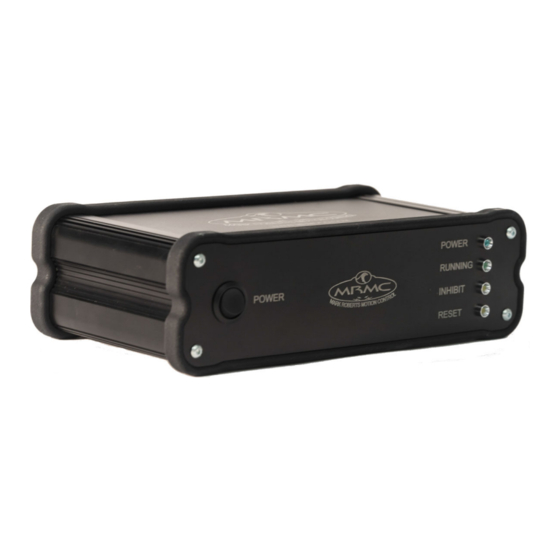
Appendix 2 Front panel RT-14 Quick Start Guide RT-14 Quick Start Guide Panel summary LEDs POWER LED: Off: Root Interface Card not powered. On: Root Interface Card has 3.3V. RUNNING LED: Off: Root Interface Card not running. -
Page 18: Switch
RT-14 Quick Start Guide Switch POWER: Top Out: RT-14 off Top In: RT-14 on. -
Page 19: Appendix 3 Rear Panel
2 connector on page 19. VIDEO IN connector for synchronisation signal from the camera.The RT-14 accepts and external video source, which is decoded to provide a frame sync pulse which sent to Flair for it to match the camera video frame rate and phase. This uses a standard coaxial cable. - Page 20 If the system is a Bolt, connect the cable on the Emergency Stop to the E-STOP BOLT connector on the RT-14. 13. 24V IN connector. The RT-14 requires a 3-pin, 24 Volt DC power supply. For pin-out information see 24V In connector on page 23.
-
Page 21: Connector Pin-Out Information
Serial Out is a (9-way D-type Female) connector can be used for connecting any head that uses Ulti-box. 10. N/C HHB connector HHB is a (9-way D-type Male) connector used for connecting the Hand Held box to the RT-14. +12V E-Stop E-Stop... -
Page 22: Mimic 1 Connector
RT-14 Quick Start Guide MIMIC 1 connector MIMIC 1 is a (25-way D-type Female) connector. Mimic GPO 1 (Open collector) LED 10. Mimic GPO 2 (Open collector) LED 11. Mimic GPO 3 (Open collector) LED 12. Mimic GPO 4 (Open collector) LED 13. -
Page 23: Mimic 2 Connector
RT-14 Quick Start Guide MIMIC 2 connector MIMIC 2 is a (25-way D-type Female). Mimic GPO 5 (Open collector) LED 10. Mimic GPO 6 (Open collector) LED 11. Mimic GPO 7 (Open collector) LED 12. Mimic GPO 8 (Open collector) LED 13. -
Page 24: Video In Connector
Video In connector Video In is a (BNC Female) connector used for connecting a Tri-level/ Bi-level video sync signal to the RT-14. The RT-14 can synchronize on the incoming analogue video signal through this port. Video In (HD or SD) -
Page 25: Triggers Connector
RT-14 Quick Start Guide Triggers connector The Triggers connector is a (37-way D-type Female) used to connect any trigger device with the RT-14 and its ribbon cables are 37-way D-type that have the same pin assignments: OUT1+ (Reserved: Camera start/stop control) -
Page 26: Ltc In Connector
RT-14. LTC In Tip Ring Sleeve E-Stop bolt connector E-Stop Bolt is a (9-way D-type Female) connector used for connecting the emergency stop for Bolt to the RT-14. Rig E-Stop 2 Rig E-Stop 3 Rig E-Stop 3 Rig E-Stop 2... -
Page 27: E-Stop Connector
RT-14. Rig E-Stop +12V Override switch Rig E-Stop Model Mover E-stop Model Mover E-Stop 24V In connector 24V In is a (3-pin XLR Male) connector to supply power to the RT-14. The RT-14 can run from 12-35 Volts DC. +24V... -
Page 28: Appendix 4 Specifications
RT-14 Quick Start Guide RT-14 Quick Start Guide Weight: 1.1 Kg Temperature range: 0-45 °C (32-113 °F) Humidity tolerance: 0% to 85% relative humidity, non-condensing Dimensions: All measurements are in mm: I/O Formats The following figure shows the typical applications of the RT-14. -
Page 29: Mimic Inputs
RT-14 Quick Start Guide Mimic inputs... -
Page 30: E-Stop For Bolt
RT-14 Quick Start Guide E-stop for Bolt... - Page 31 RT-14 Quick Start Guide Notes...
- Page 32 Mark Roberts Motion Control Ltd. Unit 3, South East Studios, Blindley Heath, Surrey RH7 6JP United Kingdom Telephone: +44 (0) 1342 838000 info@mrmoco.com www.mrmoco.com...
Need help?
Do you have a question about the RT-14 and is the answer not in the manual?
Questions and answers