Table of Contents

Related Manuals for Microgate SyncLink GT2E


Summary of Contents for Microgate SyncLink GT2E
- Page 1 SyncLink GT2E/GT4E Serial Adapter Hardware User’s Manual MicroGate Systems, Ltd http://www.microgate.com MicroGate® and SyncLink® are registered trademarks of MicroGate Systems, Ltd. Copyright © 2008-2020 MicroGate Systems, Ltd. All Rights Reserved...
-
Page 2: Table Of Contents
Contents Overview ............................... 3 Features ..............................3 Specifications ............................3 PCI Express ..............................3 Y-Cables ................................. 4 Signal Specifications ............................5 Single Ended Signals (RS-232/V.28) ......................5 Differential Signals (RS-422/RS-485/V.11) ....................5 Clock Polarity ............................6 Serial Interface Selection ..........................7 Differential Input Termination ........................ -
Page 3: Overview
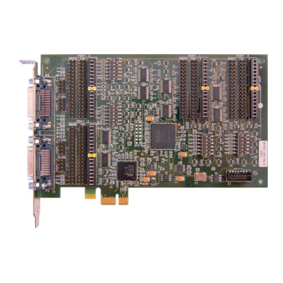
Overview The SyncLink GT2E and GT4E Serial Adapters are add-in cards for use in systems with a PCI Express expansion slot. The cards provide two (GT2E) or four (GT4E) serial ports for use by the system. A variety of serial protocols and interface standards are supported. Refer to the software documentation included with the card for details on using the card for a specific application. -
Page 4: Y-Cables
Y-Cables The card has two 60-pin connectors, each carrying two ports. Y-cables are included with the card to convert each 60-pin connector into two standard DB-25 male connectors. The GT2E card uses one 60- pin connector and includes a single Y-cable for a total of 2 ports. The GT4E card uses both 60-pin connectors and includes two Y-cables for a total of 4 ports. -
Page 5: Signal Specifications
Signal Specifications Each serial signal (control, status, data, or clock) is compatible with an electrical specification that is selected by placement of jumpers on the card. This section briefly describes the specifications supported by the card. Single Ended Signals (RS-232/V.28) SyncLink single ended signals are compatible with RS-232 and ITU V.28 standards. -
Page 6: Clock Polarity
Clock Polarity Synchronous serial communications (HDLC/Bisync/Monosync) may use separate clock signals to control the timing of data signals. One clock cycle equals one bit. There are two clock edges (rising and falling) for each clock cycle. On one edge, the transmit data output changes. On the other edge, the receive data input is sampled. -
Page 7: Serial Interface Selection
Serial Interface Selection The serial adapter supports different interface types which are selected by placement of jumpers on the card. Each port has three rows of headers (pins sticking up from the card). Each row is labeled with a port number and an interface type (RS-232, V.35, RS-422/485). Place jumpers on the header row labeled with the desired interface type. -
Page 8: Differential Input Termination
Differential Input Termination Each port on the card has optional termination of RS-422/485 differential inputs controlled by a six position switch labeled with a port number and the word ’TERM’. Each position is labeled with a number (1 at top through 6 at bottom). The on position is to the right and is labeled ‘ON’. When a switch is in the ON position, the associated differential input is terminated with 120 ohms. -
Page 9: Wire Mode Jumpers
2 Wire Mode Jumpers Some RS-485 applications use a single differential wire pair to carry data instead of separate pair for transmit and receive data. This arrangement is sometimes called ‘2 wire’ and is useful for minimizing wiring for connecting multiple end points. Only one end point sends data at any time, and all other end points can receive the data. -
Page 10: Serial Connector Pin Assignments
For interface types that use a connector different than DB-25 an adapter cable purchased from MicroGate is required. The following sections describe the jumper settings and cables for each supported standard. - Page 11 The RS-232 standard uses single ended signals on a DB-25 connector. The adapter DB-25 connector follows this standard when the port jumpers are installed for RS-232. Use any straight through 25 conductor DB-25M to DB-25F cable (such as MicroGate Part # CMF000) to connect the adapter connector to the communications equipment.
- Page 12 V.35 uses both single ended and differential signals on a 34-pin block connector. To use this standard, select the V.35 jumper and use the MicroGate V.35 cable (Part # 2534GT, picture shown below). LL, RL, and RI signals are available on the DB25 connector but are not available (NC = no connect) on the 34-pin block connector when using the V.35 cable.
- Page 13 RS-530 uses differential signals on a DB-25 connector. The adapter DB-25 connector follows this standard when the port jumpers are installed for RS-422/485. Use any straight through 25 conductor DB-25M to DB-25F cable (such as MicroGate Part # CMF000) to connect the adapter to RS-530 communications equipment.
- Page 14 Figure 7 RS-530 Cable (Part# CMF000) Figure 8 RS-449 Cable (Part# 2537FM )
- Page 15 X.21 is an interface standard using differential signals on a DB-15 connector. To use this standard, install the RS-422/485 jumpers on a port and use the MicroGate X.21 cable (Part # 2515FM). The X.21 signal names are different than those used by the adapter and other interface standards. The mapping of the X.21 signals to the adapter signals are shown in the table below.
-
Page 16: General Purpose I/O Signals
General Purpose I/O Signals The serial card has an optional 14 pin header that provides general purpose input/output (GPIO) signals for application specific uses. These signals are controlled by an application using the serial API (Windows and Linux). Each signal can be configured to be either an input or an output. Inputs can be monitored and outputs can be controlled. - Page 17 GPIO Pin Assignments Pin # Description Ground GCK0 Dedicated special purpose LVTTL input – Leave unconnected GPIO[6] GPIO[0] GPIO[7] GPIO[1] GPIO[8] GPIO[2] GPIO[9] GPIO[3] GPIO[10] GPIO[4] GPIO[11] GPIO[5] The GT adapter has a total of 12 general purpose I/O signals (GPIO[0] to GPIO[11]). By default on power up all GPIO signals are configured as inputs (direction control = 0).
-
Page 18: Frequency Synthesizer
CLK2 and CLK3 are unconnected. Sample code for programming the synthesizer through the GPIO portion of the serial API is available from Microgate. The maximum synthesizer frequency supported by the serial controller is 66MHz.
Need help?
Do you have a question about the SyncLink GT2E and is the answer not in the manual?
Questions and answers