Table of Contents
Advertisement
Quick Links
DXiP Rack and Sliding Tray
Rack Solutions
Quick Start Guide
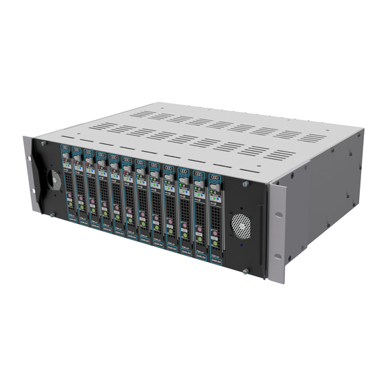
Overview
The DXiP Rack and Sliding Tray is a rack mounted enclosure that you can fit:
with a sliding tray
■
Tools
P2 Posidriv and flat-blade screwdrivers;
■
anti-static wrist strap (if handling cards or modules);
■
3-mm Allen key or T15 Torx tool (optional).
■
Install the DXiP rack with the sliding tray assembly
You must install the sliding tray in position before you attach the DXiP rack to it.
To fit the optional cable tie bar, see
Set the adjustable arms to the correct depth
1. Remove all packaging.
2. Use the Allen key or Torx tool to undo the bolts on the arms. See
3. Measure the depth between the front and rear cabinet rails.
4. Set both arms to the correct depth and tighten the bolts. See
5. Measure the adjusted length and make sure it is the same on both arms as the
depth measured for the cabinet.
Figure 1:
Adjust the depth of the arms correctly
Install the sliding tray
1. Install two caged nuts with a 1U separation (3 holes apart) on each rear rail of
the cabinet at the required location for the rack. See
2. Install two caged nuts with a 1U separation (3 holes apart) on each front rail of
the cabinet at the same height as the rear fixings. See
3. With the tray in the closed position, lift the sliding tray assembly into position.
4. Use a flat-blade screwdriver to attach the right arm to the rear rail and front
rail with four M6 screws into the caged nuts. See
5. Use a flat-blade screwdriver to attach the left arm to the rear and front rail
with four M6 screws into the caged nuts. See
Figure 2:
Install the arms of the sliding tray to the cabinet rails
Adjustable fixing brackets
There are two adjustable fixing brackets, each with six mounting holes, that attach
in one of two positions to the four holes in the side of the DXiP rack:
DXiP rack flush with the front of the cabinet (see
■
DXiP recessed (see
Figure
4). The brackets are fitted in a forward position.
■
Figure 3:
Bracket in flush position
www.amulethotkey.com
without a sliding tray
■
.
Figure
Figure
1.
Figure
2.
Figure
2.
Figure
2.
Figure
2.
Figure
3);
Figure 4:
Bracket in recessed position
Attach the fixing brackets for a DXiP rack with no sliding tray
When a sliding tray assembly is present, fit the brackets in the flush position.
1. Use the P2 screwdriver to attach the adjustable brackets to the sides of the
rack with the M4 screws in the front four holes of the bracket. See
1.
Figure 5:
Install 4 M4 screws in the front positions for the sliding tray
Install the DXiP rack
1. Press the leaf spring at the front right side to move the tray to the out position.
2. Make sure the tray is locked in position.
3. Lift the rack (with the brackets fitted in the flush position) up and onto the
sliding tray.
4. Make sure the lugs on the bottom of the rack locate with the holes in the tray
and that the back of the rack sits against the stops. See
5. Use the four spring-loaded thumbscrews on the bottom of the sliding tray to
attach the rack to the sliding tray. See
Figure 6:
Install the DXiP rack onto the sliding tray assembly
Install the DXiP rack without the sliding tray
Attach the fixing brackets for a DXiP rack with a sliding tray
Attach the mounting brackets in either position shown in
flush: use the P2 screwdriver to attach the adjustable brackets to the sides
■
of the rack with the M4 screws in the front four holes of the bracket;
recessed: use the P2 screwdriver to attach the adjustable brackets to the
■
sides of the rack with the M4 screws in the rear four holes of the bracket.
The recessed position sets the rack away from the the front of the cabinet.
This creates additional space for the cables that attach to the front panel.
Install the DXiP rack in the cabinet
1. Install four caged nuts to the front rail of the cabinet (five holes apart) in the
3U space where the DXiP rack will go.
2. Lift the rack, with the adjustable mounting brackets fitted, into place and use a
flat-blade screwdriver to attach the rack to the front rails of the cabinet with
four M6 bolts. See
Figure
DXiP Rack and Sliding Tray Quick Start Guide v1.4 March 2019
AMULET
HOTKEY
Figure
Figure
6.
Figure 3
7.
Images show the standard dual-redundant PSU rack.
®
Figure
5.
6.
and
Figure
4:
QS-DXIP-2001
Advertisement
Table of Contents

Summary of Contents for Amulet Hotkey DXiP
- Page 1 ■ Install the DXiP rack with the sliding tray assembly You must install the sliding tray in position before you attach the DXiP rack to it. To fit the optional cable tie bar, see Installing the optional cable tie bar Set the adjustable arms to the correct depth 1.
- Page 2 The DXiP sounds an audible alarm when an alarm condition occurs. To disable the alarm sound, change the switch position on the DXiP rack. The switch is in the center of the DXiP backplane (when seen from the front) on version 7.0.0 or later.
Need help?
Do you have a question about the DXiP and is the answer not in the manual?
Questions and answers