Advertisement
Table of Contents
- 1 Specifications
- 2 Installation
- 3 Manual Operation
- 4 Entrapment Protection Accessories (Optional)
- 5 Important Notes
- 6 Limit Switch Adjustment
- 7 Power Wiring
- 8 Control Wiring
- 9 Photo Eye Installation
- 10 Important Note
- 11 Modes of Operation
- 12 Clutch Adjustment
- 13 Brake Adjustment
- 14 Testing the System
- 15 Maintenance Schedule
- Download this manual
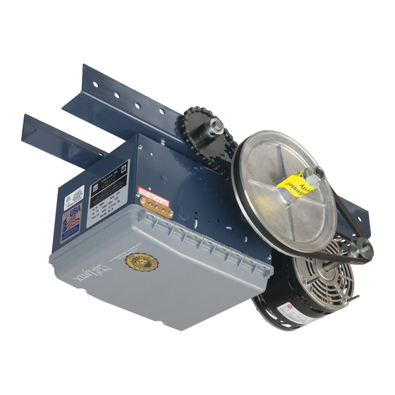
OWNER'S MANUAL
MODEL NO.
READ AND FOLLOW ALL INSTALLATION INSTRUCTIONS
SAVE THESE INSTRUCTIONS
MEDIUM DUTY DOOR OPERATOR
LDT, LDTB
1
15
4 "
PROPRIETARY AND CONFIDENTIAL
THE INFORMATION CONTAINED IN THIS
DRAWING IS THE SOLE PROPERTY OF
NAPOLEON/LYNX. ANY
REPRODUCTION IN PART OR AS A WHOLE
WITHOUT THE WRITTEN PERMISSION OF
NAPOLEON/LYNX IS
PROHIBITED.
NOT FOR RESIDENTIAL USE
This unit is intended for limited
duty applications not to exceed
12 cycles of opening and
closing per hour.
UNLE
DIM
TO
H
O
A
DRA
MATE
FINIS
Advertisement
Table of Contents

Related Manuals for Lynx Napoleon Lynx LDT


Summary of Contents for Lynx Napoleon Lynx LDT
- Page 1 4 " UNLE PROPRIETARY AND CONFIDENTIAL THE INFORMATION CONTAINED IN THIS MATE DRAWING IS THE SOLE PROPERTY OF NAPOLEON/LYNX. ANY REPRODUCTION IN PART OR AS A WHOLE WITHOUT THE WRITTEN PERMISSION OF FINIS NAPOLEON/LYNX IS PROHIBITED. NOT FOR RESIDENTIAL USE...
-
Page 2: Specifications
SPECIFICATIONS MOTOR SAFETY TYPE: Intermittent duty DISCONNECT: Quick disconnect door arm for emergency manual door 1/2 HP operation. SPEED: 1500 RPM PHOTO EYES: Included with Operator. VOLTAGE: 115V 1 Phase 60Hz REVERSING EDGE: (Optional) Electric or pneumatic sensing device attached to CURRENT: See motor nameplate the bottom edge of door. - Page 3 PREPARATION Wall Mount Track Assembly Front Idler 1. Using the center idlers and the front Trolley idler, assemble the operator rail by install- ing the idlers between the rails. Use the hex nuts on the outside and fasten them Center Idlers tight.
- Page 4 INSTALLATION WARNING Moving parts on the operator could cause possible SERIOUS INJURY. Install the operator at least 8 feet above the floor to keep people away from the moving parts. IMPORTANT NOTE: Before your operator is installed, be sure the door has been properly aligned, balanced, and is working smoothly.
-
Page 5: Installation
INSTALLATION Carpenter's Level Shim operator to a horizontal position, using the door as a support FIGURE 5 Hang the Operator Middle Support Brace 1. The illustration shows a typical method of Operator Support Brace Straight Arm hanging the operator from the ceiling. Each Curved Arm installation may vary, but in all cases side Door Bracket... -
Page 6: Manual Operation
MANUAL OPERATION WARNING WARNING Moving chain could Broken Spring(s) may cause the door to fall rapidly, cause possible SERIOUS causing SEVERE INJURY or DEATH. If possible INJURY. DISCONNECT only use the manual release when the door is closed, electric power to the otherwise use caution when using the release while the operator BEFORE manually door is open. -
Page 7: Entrapment Protection Accessories (Optional)
ENTRAPMENT PROTECTION ACCESSORIES (OPTIONAL) SENSING EDGES WARNING All types of sensing edges with an isolated normally open (N.O.) output are compatible with your operator. To reduce risk of SEVERE INJURY or This includes pneumatic and electric edges. If your door DEATH, ALWAYS install reversing sensors does not have a bottom sensing edge and you wish to when the 3-button control station is out of... -
Page 8: Power Wiring
POWER WIRING WARNING To reduce the risk of SEVERE INJURY or DEATH: • ANY maintenance to the operator or in the area near the operator MUST NOT be performed until disconnecting the electrical power and locking-out the power via the operator power switch. Upon completion of maintenance the area MUST be cleared and secured, at that time the unit may be returned to service. -
Page 9: Control Wiring
CONTROL WIRING WIRING TYPE WARNING LDT and LDTB models are equipped with the LX900 board (programing and operation, page 12, field wiring, To prevent possible SERIOUS INJURY or page 16). Upon installation the operator will be in C2 DEATH: mode (which means only constant pressure will close the •... -
Page 10: Photo Eye Installation
PHOTO EYE INSTALLATION PHOTO EYE INSTALLATION 1. Make sure that power is disconnected to the system prior to installing the photo eyes. 2. Photo eyes need to be mounted inside the building. They should be mounted on either side of the door and as close as possible to the door track to offer maximum safety precaution. -
Page 11: Modes Of Operation
LX900 PROGRAMMING AND OPERATION WARNING To reduce the risk of serious injury or death, follow these instructions carefully: • Read and follow ALL instructions. • Keep fingers and other body parts away from all moving parts of the door and gate operator system while it is being operated. - Page 12 LEARN LED will flash four (4) times, indicating that the transmitter has been programmed to the operator. The controller will learn up to 20 Lynx transmitters. Erase all transmitters: To erase all remote transmitters, press and hold the LEARN button for at least 15 seconds. During this time observe that the learn LED will turn ON and, after about 10 seconds the LEARN LED will flash three (3) times indicating that all the transmitters have been erased from the operator.
-
Page 13: Clutch Adjustment
CLUTCH ADJUSTMENT 1. Loosen the adjustment jam nuts until WARNING there is little tension on the clutch spring. To prevent possible SERIOUS INJURY or DEATH, 2. Tighten the inner jam nut gradually until install reversing sensors when the 3-button control there is just enough tension to permit station is out of sight of the door or any other control the operator to move the door smoothly... -
Page 14: Testing The System
TESTING THE SYSTEM Turn on the power to the operator. Test all controls and safety devices to make sure they are working properly. Refer to the previous instructions in this manual to make necessary adjustments. IMPORTANT NOTE: Do not leave operator power on unless all safety and entrapment devices have been tested and are working properly. Be sure you have read and understand all Safety Instructions in this manual. - Page 15 WIRING DIAGRAM (FACTORY) Thermostat Blue Blue Orange Orange Capacitor Close Limit Advanced Close Limit Open Limit LDT, LDTB...
- Page 16 WIRING DIAGRAM (FIELD) LDT, LDTB...
- Page 17 SHOP DRAWING LDT, LDTB...
Need help?
Do you have a question about the Napoleon Lynx LDT and is the answer not in the manual?
Questions and answers