Table of Contents
Advertisement
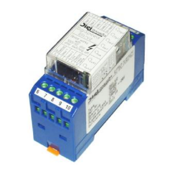
Digital switching-speed increaser
DIGISPEED DS1/V2
Version 2
englisch
Digitronic Automationsanlagen GmbH
Steinbeisstraße 3 • D - 72636 Frickenhausen • Tel. (+49)7022/40590-0 • Fax -10
Auf der Langwies 1 • D - 65510 Hünstetten-Wallbach • Tel.(+49)6126/9453-0 • Fax -42
Internet: http://www.digitronic.com • E-Mail: mail@digitronic.com
2 rue René Laennec 51500 Taissy France
E-mail:hvssystem@hvssystem.com
Fax: 03 26 85 19 08, Tel : 03 26 82 49 29
Site web : www.hvssystem.com
Advertisement
Table of Contents

Subscribe to Our Youtube Channel
Summary of Contents for Digitronic DIGISPEED DS1/V2
- Page 1 Steinbeisstraße 3 • D - 72636 Frickenhausen • Tel. (+49)7022/40590-0 • Fax -10 Auf der Langwies 1 • D - 65510 Hünstetten-Wallbach • Tel.(+49)6126/9453-0 • Fax -42 Internet: http://www.digitronic.com • E-Mail: mail@digitronic.com 2 rue René Laennec 51500 Taissy France E-mail:hvssystem@hvssystem.com Fax: 03 26 85 19 08, Tel : 03 26 82 49 29 Site web : www.hvssystem.com...
- Page 2 We would be grateful for any communication relating to any errors you may have found. UP-date You can also obtain this instruction manual on the Internet at http://www.digitronic.com in the latest version as PDF file. Qualified personnel This device may only be started and operated by qualified staff.
-
Page 3: Table Of Contents
4.2. Switching mode 2..........................8 4.3. Switching mode3..........................9 4.4. Switching mode4..........................10 4.5. Configuration of the switching-modes at DIGISPEED DS1/V2............11 5. Commisioning ............................ 11 5.1. The status LEDs ..........................12 6. Recovery time for the DIGISPEED-DS2 .................... 12 7. -
Page 4: Introduction
Digitronic Digitaler Schaltbeschleuniger Automationsanlagen GmbH DIGISPEED DS1/V2 1. Introduction: All magnetically influenced switching links e.g. magnetic valves or relais undergo a certain switching delay. This delay consist of the following coefficients: 1. the time, needed to establish the magnetic field, 2. -
Page 5: Functional Mode
Digitronic Digitaler Schaltbeschleuniger Automationsanlagen GmbH DIGISPEED DS1/V2 3. Functional mode 3.1. 3.1.Switching behaviour of switching links with flywheeling diods Normally magnetical switching links are switched on simply by connecting them to 24V DC. In the diagram shown here, this is done at the time of 0ms. The inductivity causes a slow establishing of the magnetic field and therefore a slow establishing of the magnetic force. -
Page 6: Behaviour Of Switching Links With Digispeed During Switching On Or Off
Digitronic Digitaler Schaltbeschleuniger Automationsanlagen GmbH DIGISPEED DS1/V2 3.2. Behaviour of switching links with DIGISPEED during switching on or off Being switched on DIGISPEED gives an overload impulse up to 100V DC to an adjusted time (here 5ms) upon the switching link's coil. By this over-energizing the magnetic field is established in a quarter of the time and has four times the force for a short time. -
Page 7: Switching Modes In Digispeed
Digitronic Digitaler Schaltbeschleuniger Automationsanlagen GmbH DIGISPEED DS1/V2 4. Switching modes in DIGISPEED DIGISPEED can be programed for four types of Logic-behaviour. This gives the user the possibility to process time-critical Logic-function out of an PLC-controll. 4.1. Switching mode 1 (factory preset) Switching mode 1 is the DIGISPEED's standard mode. -
Page 8: Switching Mode 2
Digitronic Digitaler Schaltbeschleuniger Automationsanlagen GmbH DIGISPEED DS1/V2 4.2. Switching mode 2 Switching mode 2 includes an enableling - input E3 (AND - Linkage). over energ. over energ. Impul. length Time-Diagram: Input 4 Duration of the overenergizing impulse 0 VDC 2 ms... -
Page 9: Switching Mode3
Digitronic Digitaler Schaltbeschleuniger Automationsanlagen GmbH DIGISPEED DS1/V2 4.3. Switching mode3 Switching mode 3 was designed specially for magnetic double-coils (drive elements). over energ. over switch energ. Impuls. length Time-Diagram: Input 3 Input 4 Ü-Zeit * 0 VDC 0 VDC 1 ms... -
Page 10: Switching Mode4
Digitronic Digitaler Schaltbeschleuniger Automationsanlagen GmbH DIGISPEED DS1/V2 4.4. Switching mode4 Switching mode 4 includes an SR - Flipflop - Logic (SET-RESET-Logic) with broken-wire security for the reset input. over length over length Impuls. length Time-diagram: Input 3 Input 4 Duration of the over-energizing impulse... -
Page 11: Configuration Of The Switching-Modes At Digispeed Ds1/V2
Automationsanlagen GmbH DIGISPEED DS1/V2 4.5. Configuration of the switching-modes at DIGISPEED DS1/V2 To set a switching-mode of the DIGISPEED use the switches DIP1 and DIP2 of the fourfold DIP - Switch. It is located behind the drilling in the transparent sheet on the device's right side. -
Page 12: The Status Leds
Digitronic Digitaler Schaltbeschleuniger Automationsanlagen GmbH DIGISPEED DS1/V2 5.1. The status LEDs The DIGISPEED is equiped with 7 status LEDs, that light the terminal allocation under the transparent sheet from behind. For every LED a specific symbol was printed on the connection allocation. -
Page 13: Terminal Allocartion
Terminal10 Do not connect!(for the internal condensors discharging only) 8. Examples for connection Note: The picture shows an DIGISPEED DS1/V2, set to 5ms over-energizing time without galvanical separation at an S5-PLC. Ausgabe: August 04 Seite: 13 2 rue René Laennec 51500 Taissy France E-mail:hvssystem@hvssystem.com... -
Page 14: Dimensions
Digitronic Digitaler Schaltbeschleuniger Automationsanlagen GmbH DIGISPEED DS1/V2 9. Dimensions 10. Technical Data DisplayAnzeigen............7 LED for status: 4x inputs, 1x state of service 2x outputs+ Supply voltage............24V DC ±20%, min. 5 Amp. Current input ............max. 8A top-current in the moment of switching Number of inputs............
Need help?
Do you have a question about the DIGISPEED DS1/V2 and is the answer not in the manual?
Questions and answers