Table of Contents
Advertisement
Operating instructions
UNIVERSAL gateway for serial diagnostic
Operating instructions. . . . . . . . . . . .pages 1 to 18
EN
Original
Content
1
About this document
1.1 Function . . . . . . . . . . . . . . . . . . . . . . . . . . . . . . . . . . . . . . . . . . . . . .1
1.2 Target group: authorised qualified personnel. . . . . . . . . . . . . . . . . .1
1.3 Explanation of the symbols used . . . . . . . . . . . . . . . . . . . . . . . . . . .1
1.4 Appropriate use . . . . . . . . . . . . . . . . . . . . . . . . . . . . . . . . . . . . . . . .2
1.5 General safety instructions . . . . . . . . . . . . . . . . . . . . . . . . . . . . . . .2
1.6 Warning about misuse . . . . . . . . . . . . . . . . . . . . . . . . . . . . . . . . . . .2
1.7 Exclusion of liability . . . . . . . . . . . . . . . . . . . . . . . . . . . . . . . . . . . . .2
2
2.1 Ordering code . . . . . . . . . . . . . . . . . . . . . . . . . . . . . . . . . . . . . . . . .2
2.2 Purpose . . . . . . . . . . . . . . . . . . . . . . . . . . . . . . . . . . . . . . . . . . . . . .2
2.3 Technical data . . . . . . . . . . . . . . . . . . . . . . . . . . . . . . . . . . . . . . . . .2
3
3.1 General mounting instructions . . . . . . . . . . . . . . . . . . . . . . . . . . . . .3
4
4.1 General information for electrical connection. . . . . . . . . . . . . . . . . .3
5
5.1 Installation SD interface . . . . . . . . . . . . . . . . . . . . . . . . . . . . . . . . . .3
5.2 Installation field bus . . . . . . . . . . . . . . . . . . . . . . . . . . . . . . . . . . . . .3
5.3 LED Signals . . . . . . . . . . . . . . . . . . . . . . . . . . . . . . . . . . . . . . . . . . .3
5.4 UNIVERSAL gateway commissioning . . . . . . . . . . . . . . . . . . . . . . .3
6
6.1 Field bus system settings. . . . . . . . . . . . . . . . . . . . . . . . . . . . . . . . .4
6.2 Transmission parameter setting (Baud rate) . . . . . . . . . . . . . . . . . .4
7
7.1 Teaching in SD devices (Teach function) . . . . . . . . . . . . . . . . . . . . .5
with fixed address range . . . . . . . . . . . . . . . . . . . . . . . . . . . . . . . . .5
8
8.1 Communication with downstream PLC . . . . . . . . . . . . . . . . . . . . . .5
8.2 UNIVERSAL gateway field bus data . . . . . . . . . . . . . . . . . . . . . . . .5
8.3 SD slave field bus data . . . . . . . . . . . . . . . . . . . . . . . . . . . . . . . . . .5
8.4 Arrangement of the SD bytes in the field bus protocol. . . . . . . . . . . 6
8.5 Reading acyclic data from an SD slave . . . . . . . . . . . . . . . . . . . . . .6
8.6 Table 1: Command overview and response data. . . . . . . . . . . . . . .6
8.7 Table 2: SD master diagnostics, SD system error . . . . . . . . . . . . . .7
8.8 Table 3: SD slave condition data . . . . . . . . . . . . . . . . . . . . . . . . . . .7
8.9 Table 4: SD slave diagnostics data . . . . . . . . . . . . . . . . . . . . . . . . .8
9
9.1 Series wiring evaluation . . . . . . . . . . . . . . . . . . . . . . . . . . . . . . . . . .8
10.1 PROFINET IO . . . . . . . . . . . . . . . . . . . . . . . . . . . . . . . . . . . . . . . .9
10.2 PROFINET IRT (Integrated Switch) . . . . . . . . . . . . . . . . . . . . . .10
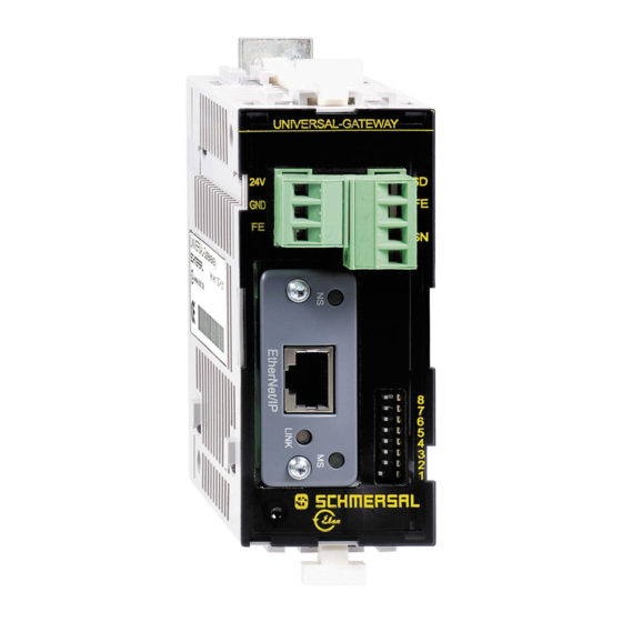
10.3 Ethernet/IP . . . . . . . . . . . . . . . . . . . . . . . . . . . . . . . . . . . . . . . . . 11
10.4 DeviceNet . . . . . . . . . . . . . . . . . . . . . . . . . . . . . . . . . . . . . . . . . .12
10.5 CC-Link . . . . . . . . . . . . . . . . . . . . . . . . . . . . . . . . . . . . . . . . . . . .13
10.6 CANopen. . . . . . . . . . . . . . . . . . . . . . . . . . . . . . . . . . . . . . . . . . .14
10.7 Modbus/TCP . . . . . . . . . . . . . . . . . . . . . . . . . . . . . . . . . . . . . . . .15
10.8 EtherCAT. . . . . . . . . . . . . . . . . . . . . . . . . . . . . . . . . . . . . . . . . . .16
1. About this document
1.1 Function
This operating instructions manual provides all the information you
need for the mounting, set-up and commissioning to ensure the safe
operation and disassembly of the the product.
The operating instructions must be available in a legible condition and a
complete version in the vicinity of the device.
1.2 Target group: authorised qualified personnel
All operations described in this operating instructions manual must
be carried out by trained specialist personnel, authorised by the plant
operator only.
Please make sure that you have read and understood these operating
instructions and that you know all applicable legislations regarding
occupational safety and accident prevention prior to installation and
putting the component into operation.
The machine builder must carefully select the harmonised standards
to be complied with as well as other technical specifications for the
selection, mounting and integration of the components.
1.3 Explanation of the symbols used
Information, hint, note:
This symbol is used for identifying useful additional
information.
Caution: Failure to comply with this warning notice could
lead to failures or malfunctions.
Warning: Failure to comply with this warning notice could
lead to physical injury and/or damage to the machine.
EN
SD-I-U-...
1
Advertisement
Table of Contents

Related Manuals for schmersal SD-I-U Series


Summary of Contents for schmersal SD-I-U Series
-
Page 1: Table Of Contents
Operating instructions UNIVERSAL gateway for serial diagnostic SD-I-U-... Communication 8.1 Communication with downstream PLC ..... .5 8.2 UNIVERSAL gateway field bus data ......5 8.3 SD slave field bus data . -
Page 2: Appropriate Use
In this way, a series-wired chain of maximum 31 either identical or different components can be set up. For the evaluation, the serial Further technical information can be found in the Schmersal diagnostic cable is connected to the here-described UNIVERSAL catalogues or in the online catalogue on the Internet: gateway. -
Page 3: Mounting
Operating instructions UNIVERSAL gateway for serial diagnostic SD-I-U-... 3. Mounting 5.3 LED Signals SD-LED Green ON = SD interface normal operation 3.1 General mounting instructions Red ON = SD interface fault The SD-I-U- … UNIVERSAL gateway is designed as a control cabinet Teach-LED yellow = SD interface teach error device with protection class IP20 for snapping onto a standard DIN rail. -
Page 4: Settings
"Anybus IPconfig Setup", which is available to download at www.schmersal.com. With the SD-I-U-EC EtherCAT UNIVERSAL gateway, DIP switch 1 is used instead of the DHCP function to switch between Schmersal and HMS-Vendor ID (for legacy systems) DIP switch 1 OFF (right): Schmersal ID DIP switch 1 ON (left): HMS ID This function is available from gateway firmware version V1.02. -
Page 5: Teaching In Sd Devices
The ESI, GSD, GSDML or EDS files for the various field bus Arrangement and identification of the SD bus devices on the bus are modules are available for download at www.schmersal.com. then stored in the memory and compared with the devices on the SD interface after each switch-on. -
Page 6: Arrangement Of The Sd Bytes In The Field Bus Protocol
Operating instructions UNIVERSAL gateway for serial diagnostic SD-I-U-... 8.4 Arrangement of the SD bytes in the field bus protocol Request for all field bus systems (OUTPUT byte control, sending of request data to SD slaves) Byte no. Byte 00 Byte 01 Byte 02 Byte 03 Byte 62... - Page 7 Operating instructions UNIVERSAL gateway for serial diagnostic SD-I-U-... The device category of an SD slave can be found in the respective operating instructions for the device. The following device categories have already been defined: Device categories Hex: 30 CSS 34, Safety sensor Hex: 31 AZM 200, Solenoid interlock "Z"...
-
Page 8: Wiring Example
For convenient wiring and series-wiring of SD devices, the SD junction boxes PFB-SD-4M12-SD (variant for the field) and PDM-SD-4CC-SD (variant for control cabinet on carrier rail) are available along with additional comprehensive accessories. Detailed information is available on the Internet, www.schmersal.net. -
Page 9: Description Of Field Bus Modules
Operating instructions UNIVERSAL gateway for serial diagnostic SD-I-U-... About the Anybus-CompactCom PROFINET IO 1-2 Description of field bus modules Front View 10.1 PROFINET IO Item Network Status LED Module Status LED Link/Activity LED Ethernet Interface Network Status LED Note: A test sequence is performed on this LED during startup. LED State Description Comments... -
Page 10: Profinet Irt (Integrated Switch)
Operating instructions UNIVERSAL gateway for serial diagnostic SD-I-U-... Description of field bus modules PROFINET IRT (Integrated Switch) 10.2 PROFINET IRT (Integrated Switch) -
Page 11: Ethernet/Ip
Operating instructions UNIVERSAL gateway for serial diagnostic SD-I-U-... About the Anybus-CompactCom EtherNet/IP 1-2 Description of field bus modules Front View 10.3 Ethernet/IP Item Network Status LED Module Status LED Link/Activity Ethernet Interface Network Status LED Note: A test sequence is performed on this LED during startup. LED State Description No power or no IP address... -
Page 12: Devicenet
Operating instructions UNIVERSAL gateway for serial diagnostic SD-I-U-... About the Anybus-CompactCom DeviceNet 1-2 Description of field bus modules Front View 10.4 DeviceNet Item Network Status LED Module Status LED DeviceNet Connector Network Status State Indication Not online / No power Green On-line, one or more connections are established Flashing Green (1 Hz) -
Page 13: Cc-Link
Operating instructions UNIVERSAL gateway for serial diagnostic SD-I-U-... About the Anybus-CompactCom CC-Link 1-2 Description of field bus modules Front View 10.5 CC-Link Item Run LED Error LED CC-Link Interface Run LED State Meaning - No network participation, timeout status (no power) Green - Participating, normal operation - Major fault (FATAL error) -
Page 14: Canopen
Operating instructions UNIVERSAL gateway for serial diagnostic SD-I-U-... About the Anybus-CompactCom CANopen 1-2 Description of field bus modules Front View 10.6 CANopen Item RUN LED ERROR LED CANopen Interface a. The flash sequences for these LEDs are defined in DR303-3 (CiA). RUN LED LED State Indication... -
Page 15: Modbus/Tcp
Operating instructions UNIVERSAL gateway for serial diagnostic SD-I-U-... About the Anybus-CompactCom Modbus/TCP 1-2 Description of field bus modules Front View 10.7 Modbus/TCP Item Network Status LED Module Status LED Link/Activity Ethernet Interface Network Status LED Note: A test sequence is performed on this LED during startup. LED State Description No power or no IP address... -
Page 16: Ethercat
1.3 Front View About the Anybus-CompactCom EtherCAT 4 Operating instructions UNIVERSAL gateway for serial diagnostic SD-I-U-... 1.3 Front View Ethernet Connector Description of field bus modules Item 10.8 EtherCAT RUN LED Ethernet Connector ERROR LED Item EtherCAT (port 1) RUN LED EtherCAT (port 2) ERROR LED Link/Activity (port 1) -
Page 17: Eu Declaration Of Conformity
UNIVERSAL gateway for serial diagnostic SD-I-U-... EU Declaration of conformity EU Declaration of conformity Original K.A. Schmersal GmbH & Co. KG Möddinghofe 30 42279 Wuppertal Germany Internet: www.schmersal.com We hereby certify that the hereafter described components both in their basic design and construction conform to the applicable European Directives. - Page 18 K.A. Schmersal GmbH & Co. KG Möddinghofe 30, D - 42279 Wuppertal Postfach 24 02 63, D - 42232 Wuppertal Phone: +49 - (0)2 02 - 64 74 - 0 Telefax: +49 - (0)2 02 - 64 74 - 1 00 E-Mail: info@schmersal.com...
Need help?
Do you have a question about the SD-I-U Series and is the answer not in the manual?
Questions and answers