Sign In
Upload
Download
Table of Contents
Contents
Add to my manuals
Delete from my manuals
Share
URL of this page:
HTML Link:
Bookmark this page
Add
Manual will be automatically added to "My Manuals"
Print this page
×
Bookmark added
×
Added to my manuals
Manuals
Brands
CBS Manuals
Stereo System
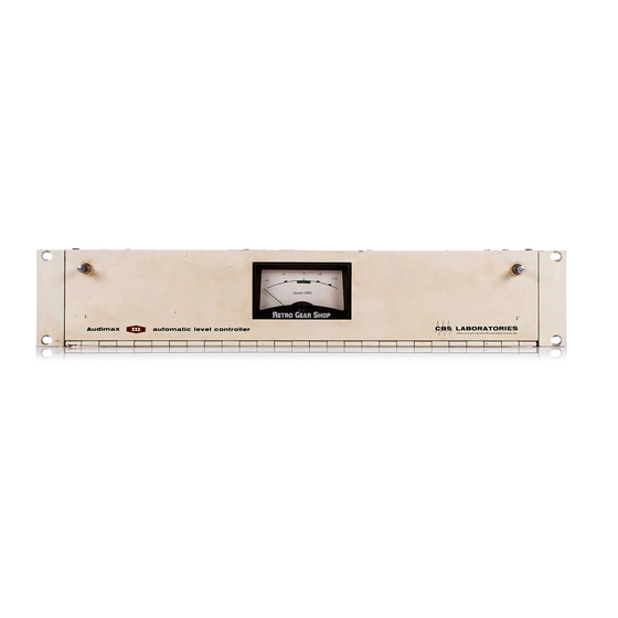
AUDIMAX III
Operating and maintenance instructions manual
CBS AUDIMAX III Operating And Maintenance Instructions Manual
Automatic level control
Hide thumbs
1
2
Table Of Contents
3
4
5
6
7
8
9
10
11
12
13
14
15
16
17
18
19
20
21
22
23
24
25
26
27
28
29
30
31
32
page
of
32
Go
/
32
Contents
Table of Contents
Bookmarks
Table of Contents
Table of Contents
Section I - Introduction
General
Warranty
Factory Service and Repair
Specifications
Section II - Installation Procedures
Unpacking
Physical Installation
Electrical Installation
Electrical Connections
Section III - Setup Procedure
Level Adjustment
Variations from Standard Operating Procedures
Gated Gain Stabilizer
Function Switch
Limited Dynamic Range Applications
Stereophonic Operation
Section IV - Theory of Operation
General
Circuit Operation
Gated Gain Stabilization
Function Switch and Meter
Stereophonic Adapter
Section V - Maintenance
General
Servicing the Main Amplifier
Servicing the Gated Gain Stabilizer
Servicing the Logic Board and Memory Unit
Transient Performance
Bulb Replacement
Circuit Board Interconnections
Section VI - Parts List
Audimax III
Stereophonic Adapter
Advertisement
Quick Links
Download this manual
~-
DO
AUDIMAX® III
AUDIMAX® III S
Automatic level control
OPERATI NG
AND
MAl NTENANCE
I NSTRUCTI ONS
Table of
Contents
Previous
Page
Next
Page
1
2
3
4
5
Advertisement
Table of Contents
Need help?
Do you have a question about the AUDIMAX III and is the answer not in the manual?
Ask a question
Questions and answers
Subscribe to Our Youtube Channel
This manual is also suitable for:
Audimax iii s
444
445
Table of Contents
Print
Rename the bookmark
Delete bookmark?
Delete from my manuals?
Login
Sign In
OR
Sign in with Facebook
Sign in with Google
Upload manual
Upload from disk
Upload from URL

Need help?
Do you have a question about the AUDIMAX III and is the answer not in the manual?
Questions and answers