Advertisement
Quick Links
E-CPU10FC-I-1117
E-SPTS-I-0809
EQUIPMENT DEVELOPMENT CO., INC.
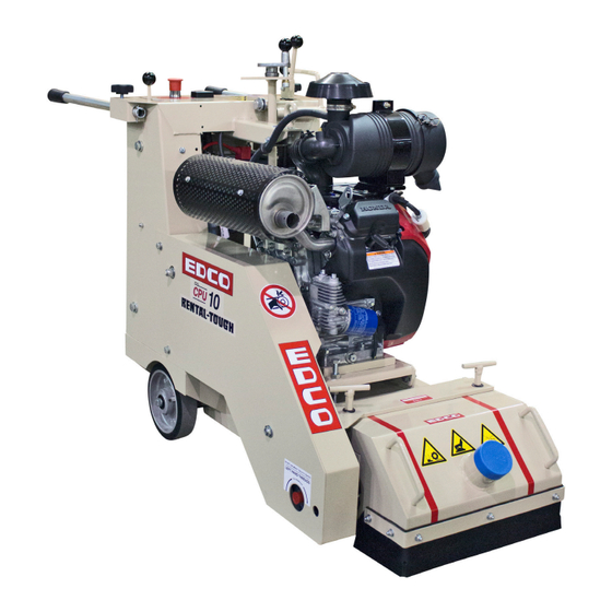
Operator's Instruction Manual
MODELS CPU-10FC
Gasoline and Electric
Self-Propelled Concrete/Asphalt Scarifier
100 Thomas Johnson Drive, Frederick, MD 21702-4600 USA
Phone: 301-638-3326 • 301-663-1600
Fax: 800-447-3326 • 301-663-1607
EQUIPMENT DEVELOPMENT CO., INC.
edcoinc.com • sales@edcoinc.com
Advertisement

Subscribe to Our Youtube Channel
Related Manuals for Edco CPU-10FC


Summary of Contents for Edco CPU-10FC
- Page 1 E-CPU10FC-I-1117 E-SPTS-I-0809 EQUIPMENT DEVELOPMENT CO., INC. Operator’s Instruction Manual MODELS CPU-10FC Gasoline and Electric Self-Propelled Concrete/Asphalt Scarifier 100 Thomas Johnson Drive, Frederick, MD 21702-4600 USA Phone: 301-638-3326 • 301-663-1600 Fax: 800-447-3326 • 301-663-1607 EQUIPMENT DEVELOPMENT CO., INC. edcoinc.com • sales@edcoinc.com...
- Page 2 E-CPU10FC-I-1117 EQUIPMENT DEVELOPMENT CO., INC. READ AND UNDERSTAND THE OPERATORS INSTRUCTION MANUAL THOROUGHLY BEFORE ATTEMPTING TO OPERATE THIS EQUIPMENT. Death or serious injury could occur if this machine is used improperly. SAFETY SAFETY MESSAGES • Do not disconnect power by pulling cord. To disconnect, grasp the plug, not the cord.
-
Page 3: Table Of Contents
Specifications di ensions are for HOW TO ORDER REPAIR PARTS reference only and subject to change. To insure product safety and reliability, always use genu- ine EDCO replacement parts when making repairs to the Model CPU-10FC equipment. Length (L) 47”/120cm... -
Page 4: What To Expect
We at EDCO are prepared to assist the user. We can Since the maximum depth of cut is 1/2” (2 cm) in increments of provide technical information and comparison data on 1/8”... -
Page 5: Safety Guideline
E-CPU10FC-I-1117 E-SPTS-I-0809 EQUIPMENT DEVELOPMENT CO., INC. Read and understand this Operator’s Instruction Manual, and the Engine Manufacturer’s Owner’s Manual before operating this equipment. Death of serious injury can result if this machine is used improperly. Safety Guidelines Eye and ear protection must be worn at all times while the saw is in use. During normal operation, sound pressure levels exceed 85dBA. -
Page 6: Operator Controls
E-CPU10FC-I-1117 EQUIPMENT DEVELOPMENT CO., INC. Operating Controls Cutter Head Lever Water Hook Up Clutch Lever Fuel Lockoff Solenoid Toggle Depth Control Knob For Propane Models Only. Lifting Eye (Not Shown) E-Stop Ignition Switch, Choke & Throttle are Drive Control Lever located on Remote Control on Engine Handle Locking Knobs Hour Meter... -
Page 7: Operating Instructions
Verify that the electrical current being supplied is the proper voltage and phase required to run the equipment • Check motor rotation. Cutter drum rotation on the model CPU-10FC is “upcut.” DO NOT use if drum rotation is incorrect - have a qualified electrician make the necessary change in the main control panel or motor connection box. - Page 8 • Before hoisting, always inspect frame and attachment hardware for damage. Use proper and safe hoisting techniques and approved hardware. CPU-10FC weight is approximately 530 lbs (240 kg). Never hoist a machine over top of where people are working or standing. Never hoist a machine while the engine is running.
- Page 9 Cutting Heads / Drums: • Drum assembly revolves at approximately 2000 R. P. M.; Model CPU-10FC is an “up-cut” planer. Depth of cut is completely determined by the material to be cut, horsepower of the engine and spacing of the cutter wheels on the cutter head.
- Page 10 To keep thermoplastic from heating up, we recommend to spray water on the work surface whenever possible. Note: If the CPU-10FC will be used for traffic line removal, the optional front outrigger wheel assembly will follow the contour of the surface to be cut. By doing this you can control the amount of surface to be removed with little or no damage beneath the paint.
- Page 11 E-CPU10FC-I-1117 E-SPTS-I-0809 EQUIPMENT DEVELOPMENT CO., INC. Outrigger Wheel Assembly: (Optional) Outrigger wheel assembly (Figure 5) is designed to al- Outrigger Wheel low the drum to follow the contour of the slab. Wheels Assembly are aligned with cutting drum to follow highs and lows (Optional) of the slab removing a consistent depth over the entire surface.
-
Page 12: Maintenance
Always work on a flat and level surface. Carbon Canister The CPU-10FC is equipped with a charcoal canister to create a sealed fuel system and re- route any vapors from the tank back to the airbox on the engine for burning. This unit also has a teathered fuel cap with viton gasket and evaporation resistent fuel lines. - Page 13 E-CPU10FC-I-1117 E-SPTS-I-0809 EQUIPMENT DEVELOPMENT CO., INC. Important! • Check oil level before operation. Change engine oil and filter according to engine manufacturers recommendations. • Clean air filter element daily. Belts: • On new equipment, and after replacing a set of belts, they should be re-tensioned after the first four hours of use. •...
-
Page 14: Drum Bearing Replacement
E-CPU10FC-I-1117 EQUIPMENT DEVELOPMENT CO., INC. Drum Bearing Replacement Important! 1. Remove hood and belt cover. 2. Remove spindle shaft. Remove 2 left hand nuts on left side of shaft. Note: These nuts loosen to the right. Set aside. Remove shaft. If the debris has hardened on shaft you might need to tap out with a hammer and drift pin. Remove drum and set aside. -
Page 15: Machine Schedule
E-CPU10FC-I-1117 E-SPTS-I-0809 EQUIPMENT DEVELOPMENT CO., INC. Repairs are to be preformed Read and follow all instructions by EDCO or by approved in the Engine Manufacturer’s EDCO repair technicians. Owner’s Manual. Maintenance Schedule Follow Engine Before Daily Every 4 Every each... - Page 16 E-CPU10FC-I-1117 EQUIPMENT DEVELOPMENT CO., INC. Safety Symbols This symbol means that the guards must remain in place while the engine/motor on the machine is running because death or personal injury may result. (Yellow background with black pictogram and black outline) This symbol means that there are moving parts and if feet/fingers/digits are inserted under any edge of the cutter/grinder/saw cover while the engine/motor on the machine is running that personal injury and loss of foot/fingers/digits may result.
- Page 17 E-CPU10FC-I-1117 E-SPTS-I-0809 EQUIPMENT DEVELOPMENT CO., INC. Safety Symbols This symbol means that the Operator’s, owners, instruction and/or manufacturer(s) manuals must be read and understood before operating or attempting to operate this electrical, gasoline, diesel or propane powered equipment, failure to do so can result in personal injury and possible death. (Blue background with white pictogram.) This symbol means that proper eye protection must be worn/used during the operation of this equipment.
-
Page 18: Smi Dust And Silica Warning
E-CPU10FC-I-1117 EQUIPMENT DEVELOPMENT CO., INC. DUST AND CRYSTALLINE SILICA WARNING Grinding/cutting/drilling of masonry, concrete, metal and other materials can generate dust, mists and fumes containing chemicals known to cause serious or fatal injury or illness, such as respiratory disease, cancer, birth defects or other reproductive harm. If you are unfamiliar with the risks associated with the particular process and/or material being cut or the composition of the tool being used, review the material safety data sheets and/or consult your employer, the manufacturers/suppliers, governmental agencies such as OSHA and NIOSH and other sources... - Page 19 *Seller reserves the right to hold shipments against past due accounts. EDCO will, at its option, repair or replace, at the EDCO factory or at a point designated by EDCO, any part which shall appear to the satisfaction of EDCO inspection to have been *Seller reserves the right to alter payment terms.
- Page 20 E-CPU10FC-I-1117 EQUIPMENT DEVELOPMENT CO., INC. SURFACE PREPARATION, RESTORATION, PROFESSIONAL SAWING EQUIPMENT & HAND HELD TOOLS 100 THOMAS JOHNSON DRIVE, FREDERICK, MD 21702 PHONE: 800-638-3326 OR 301-663-1600 Fax: 800-447-3326 or 301-663-1607 Email: sales@edcoinc.com Website: edcoinc.com Patents Pending & Issued Created 6 2014 Printed in USA ©2014 Page 20 800-638-3326 •...
Need help?
Do you have a question about the CPU-10FC and is the answer not in the manual?
Questions and answers