Table of Contents
Advertisement
Quick Links
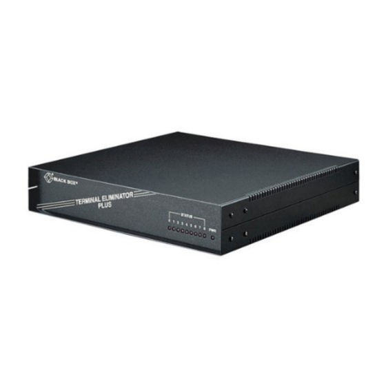
Terminal Eliminator Plus
CUSTOMER
Order toll-free in the U.S. 24 hours, 7 A.M. Monday to midnight Friday: 877-877-BBOX
FREE technical support, 24 hours a day, 7 days a week: Call 724-746-5500 or fax 724-746-0746
SUPPORT
Mail order: Black Box Corporation, 1000 Park Drive, Lawrence, PA 15055-1018
INFORMATION
Web site: www.blackbox.com • E-mail: info@blackbox.com
I N A
L I M
L E
U S
I N A
P L
R M
T E
R
S T A T U S
T O
4
3
2
1
0
MARCH 2001
TL482A-R3
TL482AE-R3
TL483-C
TL484
TL486
P W R
8
7
6
5
Advertisement
Table of Contents

Subscribe to Our Youtube Channel
Related Manuals for Black Box Terminal Eliminator Plus


Summary of Contents for Black Box Terminal Eliminator Plus
- Page 1 Order toll-free in the U.S. 24 hours, 7 A.M. Monday to midnight Friday: 877-877-BBOX FREE technical support, 24 hours a day, 7 days a week: Call 724-746-5500 or fax 724-746-0746 SUPPORT Mail order: Black Box Corporation, 1000 Park Drive, Lawrence, PA 15055-1018 INFORMATION Web site: www.blackbox.com • E-mail: info@blackbox.com...
- Page 2 FCC AND DOC/MDC STATEMENTS FEDERAL COMMUNICATIONS COMMISSION INDUSTRY CANADA RADIO FREQUENCY INTERFERENCE STATEMENTS This equipment generates, uses, and can radiate radio frequency energy and if not installed and used properly, that is, in strict accordance with the manufacturer’s instructions, may cause interference to radio communication. It has been tested and found to comply with the limits for a Class A computing device in accordance with the specifications in Subpart J of Part 15 of FCC rules, which are designed to provide reasonable protection...
- Page 3 TERMINAL ELIMINATOR PLUS NORMAS OFICIALES MEXICANAS (NOM) ELECTRICAL SAFETY STATEMENT INSTRUCCIONES DE SEGURIDAD 1. Todas las instrucciones de seguridad y operación deberán ser leídas antes de que el aparato eléctrico sea operado. 2. Las instrucciones de seguridad y operación deberán ser guardadas para referencia futura.
- Page 4 NOM STATEMENT 12. Precaución debe ser tomada de tal manera que la tierra fisica y la polarización del equipo no sea eliminada. 13. Los cables de la fuente de poder deben ser guiados de tal manera que no sean pisados ni pellizcados por objetos colocados sobre o contra ellos, poniendo particular atención a los contactos y receptáculos donde salen del aparato.
-
Page 5: Table Of Contents
5.4 Buffer Allocation ................44 5.5 Data Processing ................. 45 5.6 Master-Port Flow Control ..............53 6. Troubleshooting ..................54 6.1 Calling Black Box ................54 6.2 Shipping and Packaging ..............54 NOTE Call Technical Support at 724-746-5500 for guidance in choosing cables. -
Page 6: Specifications
CHAPTER 1: Specifications 1. Specifications Approval — FCC Class A, DOC Class/MDC classe A Interface — Serial EIA RS-232-C/CCITT V.24, each port individually selectable as DTE or DCE Protocol — Asynchronous Data Format — 7 or 8 data bits (each port individually selectable); automatically adjusts to any stop-bit setting;... -
Page 7: Introduction
TERMINAL ELIMINATOR PLUS 2. Introduction The Terminal Eliminator Plus (TEP) is named for one of its primary uses— to eliminate the need for more than one operator console in a computerized information-gathering system. The TEP allows one asynchronous terminal to serve as the operator’s console (the “master”) for up to four (eight with the... -
Page 8: The Data-Direction Modes
CHAPTER 2: Introduction 2.1 The Data-Direction Modes The Terminal Eliminator Plus operates in five basic data-direction settings (“modes”): Concentrate Only, Concentrate & Broadcast, Conversation, Transparent Conversation, and Broadcast Only. Certain commands are available in each mode; see Section 5.2. In Concentrate Only Mode (slaves → master), the TEP assembles messages received from up to four (or eight) slaves at speeds (independent on each port) of up to 19.2 Kbps. -
Page 9: The Front-Panel Leds
Status LEDs (numbered 0 through 8) and one Power LED. The Power LED will be lit when the Terminal Eliminator Plus is getting power and will be dark when the TEP is unplugged or is not getting power. Each Port-Status LEDs... -
Page 10: Installation
CHAPTER 3: Installation 3. Installation Installing the Terminal Eliminator Plus (TEP) involves between four and eight steps, depending on your application: 1. Setting the internal DIP switches. 2. Configuring the DTE/DCE shunt jumpers. 3. Tying signal ground to frame ground with jumper W1 (optional). - Page 11 TERMINAL ELIMINATOR PLUS Fig. 3-1. The Terminal Eliminator Plus’s motherboard. (BACK) PORT 4 PORT 3 PORT 2 PORT 1 PORT 0 RESET BUTTON INDIVIDUAL PORT SWITCHES SYSTEM SWITCHES (SWF & SWG) PORT 4 PORT 3 PORT 2 PORT 1 PORT 0...
- Page 12 CHAPTER 3: Installation Fig. 3-2. The 4-Port Expansion Board. (BACK) PORT 8 PORT 7 PORT 6 PORT 5 INDIVIDUAL PORT SWITCHES (PORTS 5 THRU 8) PORT 8 PORT 7 PORT 6 PORT 5 (FRONT) On the 4-Port Expansion Board (as shown above in Figure 3-2): SWH - for slave port 5 SWI -...
- Page 13 TERMINAL ELIMINATOR PLUS Table 3-1. The Master-Port DIP Switch (SWA) SWITCH-POSITION SETTING OPTION SPEED (in bps) 1200 2400 4800 9600 19,200 PARITY None Invalid Setting* Even None DATA BITS Eight Seven FLOW CONTROL/ RELOAD (Reload)** X-ON/Poll† DTR/CTS X-ON/X-OFF *When both switches are set to ON, the TEP will generate a self-test message.
- Page 14 CHAPTER 3: Installation Table 3-2. The Slave-Port DIP Switches (SWB-SWE, SWH-SWK) SWITCH-POSITION SETTING OPTION SPEED (in bps) 1200 2400 4800 9600 19,200 PARITY None Even None DATA BITS Eight Seven FLOW CONTROL DTR/CTS X-ON/X-OFF BUFFER CONTROL* Buffer data in Conversation modes only Always buffer *See Section 5.5.3.
- Page 15 TERMINAL ELIMINATOR PLUS 3.1.2. S YSTEM PTION WITCHES There are two DIP switches on the motherboard, labeled SWF and SWG (see Figure 3-1). The possible settings for these switches are listed in Table 3-3 below and Table 3-4 on page 11. The options corresponding to each setting are described in more detail in the text starting on page 12.
- Page 16 CHAPTER 3: Installation Table 3-4. The System DIP Switch SWG SWITCH-POSITION SETTING OPTION RECEIVED CARRIAGE- RETURN STRIPPING Disabled Enabled RCVD. LINE-FEED STRIPPING Disabled Enabled OTHER NONPRINTABLE- CHARACTER STRIPPING Disabled Enabled CARRIAGE-RETURN INSERT AT END OF RECORD Disabled Enabled TRANSMISSION DELAY AFTER CARRIAGE RETURNS Enabled (100-ms delay) Disabled (no delay)
- Page 17 TERMINAL ELIMINATOR PLUS 3.1.2.A Status Messages (SWF Position 1) If you want the Terminal Eliminator Plus to inform users of its current mode or of mode changes with status messages, set position 1 of DIP switch SWF to OFF: Status messages will be enabled. (For examples of these status messages, see Section 5.1.2.)
- Page 18 To improve the readability of the data that comes to the master from the slaves, you might want the Terminal Eliminator Plus to separate data from different slaves with a blank line by inserting a carriage return in front of the first line from a new slave: Set position 5 of SWF to ON.
- Page 19 TEP to leave the nonprintable characters in, set position 3 ON. 3.1.2.L Carriage-Return Insert After End of Record (SWG Position 4) If you want the Terminal Eliminator Plus to insert a carriage return at the end of each valid slave record that doesn’t already end with a carriage return, set position 4 of SWG to OFF.
-
Page 20: Configuring Shunt Jumpers For Dte Or Dce
Equipment (DTE) or Data Communications Equipment (DCE). This feature eliminates the need for crossover cables to connect your equipment to the Terminal Eliminator Plus. Standard straight-through cabling is all that is required. Table 3-5, below, shows the RS-232 signals used by the Terminal Eliminator Plus and their directions at a given port when that port is configured as DTE or DCE. -
Page 21: Tying Signal Ground To Frame Ground (Optional)
(If you are performing this upgrade on a previously installed and operated Terminal Eliminator Plus, rather than at initial installation time, unplug the TEP and remove its cover as described in Section 3.1.) First, locate the empty chip socket labeled “U6”... - Page 22 If a pin is bent, straighten the pin with a small screwdriver or pliers and then reinsert the IC. Replace the cover, plug the TEP back in, and test the unit’s buffering capacity. If the problem hasn’t been solved, contact Black Box.
-
Page 23: Expansion-Board Installation (Optional)
(If you have already set the port switches, be careful not to bump them. If you are performing this expansion on a previously installed and operated Terminal Eliminator Plus, rather than at initial installation time, unplug the TEP and remove its cover as described in Section 3.1.) 1. - Page 24 CHAPTER 3: Installation Fig. 3-4. Installing the 4-Port Expansion Board. 6. Screw the screw you removed in Step 1 through either spacer hole in the Expansion Board, into the corresponding spacer. 7. Screw the screw provided with the Expansion Board through the other spacer hole, into the other spacer.
-
Page 25: Rackmounting The Tep (Optional)
The Rackmount Kit consists only of two rackmount brackets. It does not contain the necessary hardware (screws, clips, bolts, etc.) to mount the brackets to the rack. Before installing the Terminal Eliminator Plus in a rack, make sure that all the switches and jumpers have been set to the desired settings, as described in Sections 3.1 through 3.3. - Page 26 6. Screw four mounting screws (not supplied) through the grooves in the brackets and into the clips on the rack. (As before, make sure these screws are tight.) The Terminal Eliminator Plus is now installed in your equipment rack. Fig. 3-6. Mounting the TEP in a rack.
-
Page 27: Connecting Devices To The Master And Slave Ports
(optionally) installed either of the internal upgrades, and (also optionally) mounted the TEP on a rack, you are ready to connect the Terminal Eliminator Plus to the input (slave) devices and master console: 1. If you haven’t rackmounted the TEP, and so already taken these steps, verify that the power-supply connector is properly inserted into the 4-pin male connector on the Terminal Eliminator Plus’s motherboard, then... -
Page 28: Configuration
CHAPTER 4: Configuration 4. Configuration 4.1 The Initialization Menu When you first plug in the Terminal Eliminator Plus, the TEP will immediately begin operating in either Concentrate Only or Concentrate and Broadcast Mode, depending on how you have set the system-option switch SWF, position 2 (refer to Section 2.1.2.B). - Page 29 TERMINAL ELIMINATOR PLUS (In addition to the carriage-return or enter key, which tells the TEP to accept the data as it currently appears in the entry field as correct, two other special keys are useful when you are in the middle of setting an option. You can use the backspace key to retrace your steps, so you can correct data-entry errors.
-
Page 30: Menu Options
CHAPTER 4: Configuration 4.2 Menu Options Descriptions of the initialization-menu options: 4.2.1 B EGINNING ECORD HARACTER If you allow this option to have a character value (the range is 0 to 255 decimal, 00 to FF hex, or 256 = disabled), the TEP will not recognize a record as having begun, nor will it recognize an “end-of-record”... - Page 31 TERMINAL ELIMINATOR PLUS 4.2.4 R ECORD ENGTH ERMINATES ECORDS If you allow this option to have a value other than zero (the range is 1 to 999 characters, or 0 = disabled), the TEP will regard slave records as ending when they reach this length.
- Page 32 CHAPTER 4: Configuration 4.2.7 D ISCONNECT BORT HARACTER Strings of your disconnect/abort character (which you can choose to be “N,” “O,” “P,” or “Q”) form your disconnect and abort commands, which are necessary for exiting either Conversation mode or Broadcast Only Mode and returning to the standard Concentrate mode.
-
Page 33: Operation
TERMINAL ELIMINATOR PLUS 5. Operation Once the Terminal Eliminator Plus has been installed and configured, it begins to operate continuously. This chapter details how the TEP works and how you can control it with a combination of keyboard commands, the initialization menu, and DIP switch settings. - Page 34 CHAPTER 5: Operation 5.1.2 M ASTER TATUS ESSAGES If the user sets position 1 of system switch SWF to OFF, the Terminal Eliminator Plus will send status messages to the master device. The user can get an idea of what mode the TEP is in from some of these messages: They show (a) that the unit has been reset or (b) a command to switch modes has been processed.
-
Page 35: Valid Command Strings
TERMINAL ELIMINATOR PLUS 5.2 Valid Command Strings 5.2.1 “D ” ISCONNECT To exit Broadcast Only Mode or either Conversation mode after all master- port data buffered in the TEP has been transmitted to the slave device(s), the user sends four consecutive command characters from the master device. The command character can be one of four different characters (“N,”... - Page 36 CHAPTER 5: Operation 5.2.5 “B ” ROADCAST To enter Broadcast Mode from either of the Concentrate modes, the user sends from the master device the two ASCII characters “BC” followed by a carriage-return character (ASCII [CR]). 5.2.6 “I ” NITIALIZATION To access the initialization menu (from which you can change some of the TEP’s settings) from either of the Concentrate modes, the user sends from the master device the four ASCII characters “INIT”...
-
Page 37: The Data-Direction Modes In Detail
Conversation Mode) and you wait until you receive the end of a valid record before sending the chained command string. 5.3 The Data-Direction Modes in Detail The Terminal Eliminator Plus’s five data-direction modes are described in Section 2.1. Here are more details. 5.3.1 A... - Page 38 CHAPTER 5: Operation 5.3.2 T ONVERSATION ODES Communication in the Concentrate modes is many-to-one, all slaves interacting with the master simultaneously. But there are times when the operator of the master console might need to actively interface with one selected device. For example, the operator may have reason to closely observe the data of one particular slave port, and perhaps respond with data from the console.
- Page 39 ASCADE PPLICATIONS Two or more Terminal Eliminator Plus units can be linked together to increase the number of slave ports above 4 (or 8). This is referred to as “cascading.” Run cable from slave port(s) of the “first-layer” TEP directly to the master port(s) of one or more subsidiary TEPs.
- Page 40 ODE IN ASCADE PPLICATIONS Two or more Terminal Eliminator Plus units can be linked together to share the same operator’s console. This is referred to as “cascading.” (Refer to Section 5.3.3 for the rest of the general principles.) Assuming that you’re starting from a Concentrate mode on the first-layer Terminal Eliminator Plus, to broadcast to the slave devices attached to only one third-layer TEP, send “Cn[CR]Cm[CR] BC[CR]”...
- Page 41 For example, again assuming that you’re starting from a Concentrate- mode connection to the first-layer Terminal Eliminator Plus, to broadcast to the slave devices attached to all third-layer TEPs, send “BC[CR]BC[CR] BC[CR]”.
- Page 42 X-OFF, the TEP will wait for the port to receive an X-ON character before transmitting further data to any port. OFF: With position 3 OFF, the Terminal Eliminator Plus will bypass any port that is exercising flow control. When the TEP encounters a port that...
-
Page 43: Buffer Allocation
TERMINAL ELIMINATOR PLUS Fig. 5-2. Dynamic allocation of 32K of buffer space. 5.4 Buffer Allocation A standard Terminal Eliminator Plus has 32K of RAM, with approximately 1K dedicated to program “self-storage” and 31K of RAM available for buffer space. A TEP with the 32K Memory Expansion chip installed has 64K of RAM, with approximately 5K dedicated to program “self-storage”... -
Page 44: Data Processing
CHAPTER 5: Operation 5.5 Data Processing 5.5.1 P ROCESSING OF ECEIVED ASTER The data received from the master port is always checked for commands valid in the current data-direction mode of the unit. Valid command strings are acted upon after all previous data received from the master port has been processed, with the exception of the “Abort”... - Page 45 TERMINAL ELIMINATOR PLUS any slave data is in the TEP’s internal buffer, the TEP will transmit the data to the master device in one of two different ways depending on whether the current mode is of the Concentrate or Conversation type.
- Page 46 CHAPTER 5: Operation 4. A record can optionally contain a user-selectable beginning-of-record character that the TEP must sense before it will recognize any of the above as valid. Any data received prior to the beginning-of-record character will be passed or discarded depending on the setting of position 8 of system switch SWF.
- Page 47 TERMINAL ELIMINATOR PLUS The rest of this section is an itemized list and description of all possible format options. 5.5.4.A Separate Different Slaves’ Data with a Blank Line Because data from all the slaves is combined into the master port’s output- data stream during Concentrate modes, this option will help in visually separating the different ports’...
- Page 48 CHAPTER 5: Operation NOTE: The example above assumes a carriage return follows the data to perform a line wrap. 5.5.4.D Place User-Assigned Slave Label on a Line By Itself System switch SWF position 7 ON to enable enabled: Slave #1 disabled: Slave #1 abc System switch SWF position 6 &...
- Page 49 Because the Terminal Eliminator Plus may be concentrating data from a variety of different types of devices, it may be very hard to get a consistent output to a display device unless you use the following options—for example,...
- Page 50 CHAPTER 5: Operation 5.5.4.J Insert One Carriage-Return Character at the Maximum User-Assigned Line Length, and Reset the Line Count for Every Slave [CR] Transmitted “See/Set maximum output line length” option in the initialization menu (see Section 4.2.6) 5.5.4.K. Insert One Carriage-Return Character at the End of Every Valid Record Unless the Record Already Ends With a [CR] System switch SWG position 4 OFF 5.5.4.L Insert One Line-Feed Character After Every Carriage Return Transmitted to the...
- Page 51 If the user has disabled a slave port’s “no receive” timeout, then the Terminal Eliminator Plus, after transmitting the end of one of that slave port’s records, will immediately begin looking to transmit a valid record from another slave port.
-
Page 52: Master-Port Flow Control
CHAPTER 5: Operation 5.6 Master-Port Flow Control You can prevent the Terminal Eliminator Plus from transmitting slaves’ data records to the master device by activating the flow-control method you select for the master port (DTR/CTS, X-ON/X-OFF or X-ON/poll). X-ON/poll is a special type of flow control; here’s how it works. If you select... -
Page 53: Troubleshooting
If you need to transport or ship your Terminal Eliminator Plus: • Package it carefully. We recommend that you use the original container. • Before you ship a unit for repair or return, contact Black Box to get a Return Materials Authorization (RMA) number, and make sure you... - Page 54 © Copyright 2001. Black Box Corporation. All rights reserved. 1000 Park Drive • Lawrence, PA 15055-1018 • 724-746-5500 • Fax 724-746-0746...
Need help?
Do you have a question about the Terminal Eliminator Plus and is the answer not in the manual?
Questions and answers