Advertisement
Quick Links
Advertisement

Summary of Contents for Pensa Labs D.I.Wire Pro
- Page 1 Version 19.4.16...
-
Page 2: Table Of Contents
Table Of Contents INTRODUCTION HARDWARE SETUP AND SAFETY BENDING SETTING UP WIREWARE PATH MODE SCRIPT MODE MATERIAL PROFILE MAINTAINANCE AND TROUBLESHOOTING... -
Page 3: Introduction
SECTION 1 Introduction... - Page 4 01| INTRODUCTION Introduction THE D.I.WIRE PRO D.I.WIRE PRO AND ITS COMPONENTS GETTING TO KNOW THE D.I.WIRE PRO...
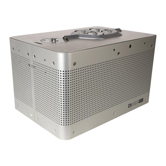
- Page 5 01 | INTRODUCTION The D.I.Wire Pro The D.I.Wire Pro is our newest desktop CNC wire bender offering the power, speed, precision and modularity that professionals need. Bend any wire material between 0.027” (0.7mm) and 0.188” (4.8mm), bend strap, and add a straightener and other accessories to optimize production.
- Page 6 01 | INTRODUCTION The D.I.Wire Pro Before Use: Use the D.I.Wire Pro only as instructed in this manual. Make sure you read all the instructions and safety precautions before using the machine. The D.I.Wire PRO is to be used by qualified personnel only.
- Page 7 01 | INTRODUCTION D.I.Wire Pro and Its Components THE MACHINE TOOLS AND ACCESSORIES* RAMP D.I.WIRE PRO BEND HEAD + BEND RING + FEED WHEELS GUIDES D.I.Wire comes assembled with your specific Bend Head, Bend Ring and Feed Wheels. Guides are custom for Keep tools and hardware somewhere safe! each material diameter.
- Page 8 01 | INTRODUCTION Getting to know the D.I. Wire Pro Take a few minutes to get oriented to the D.I.Wire Pro. TOP VIEW DETAIL Hold material in place as it Bends material around WIRE GUIDES BEND PIN is bent. Interchangeable to Bend Head.
-
Page 9: Hardware Setup And Safety
SECTION 02 Hardware Setup And Safety... - Page 10 02 | SETUP AND SAFETY Hardware Setup And Safety GETTING SET UP D.I.WIRE ORIENTATION SAFETY AND PROTECTION DO’S AND DON’TS OF THE MACHINE...
- Page 11 02 | SETUP AND SAFETY Getting Set Up Start by choosing a work area that is appropriate for your D.I.Wire. CHOOSING A WORK AREA Place the D.I.Wire away from any surface The D.I.Wire is a heavy machine. Make sure Make sure the work area is well illuminated, that could obstruct the air flow and cause you place it on a hard, flat, and sturdy surface and kept clean, free of excessive dust, debris...
- Page 12 02 | SETUP AND SAFETY D.I. Wire Orientation The D.I.Wire requires sufficient work space for the following areas: Back of the system for material loading; front of the system for part bending; and a dedicated area for the computer running WireWare SPATIAL ARRANGEMENT Caution Area BEND AREA...
- Page 13 The D.I.Wire weights 57 Kg ( 125 lb). Be safe! Seek assistance to pick it up from its case and to carry it to its assigned work area. THE D.I.WIRE PRO IS A HEAVY MACHINE AND COULD CAUSE INJURY IF LIFTED INCORRECTLY.
- Page 14 02 | SETUP AND SAFETY Bend Safety Your safety and the safety of others is very important to us, so we have provided the following safety section and other safety-related messages along the manual. Always NEVER TOUCH read and follow all safety messages. MOVING PARTS! TO STOP NEVER touch the Bend Pins or...
- Page 15 PANELS rendered unusable. Refer to the service and maintenance section for details. Always wear protective eyewear when The D.I.Wire PRO needs su cient air flow for EYE + HAND OVERHEATING operating the D.I.Wire. Small bits of wire proper ventilation. See the Setting Up section PROTECTION can fly out unexpectedly when bending...
-
Page 16: Bending
SECTION 03 Bending 2x R25 2x R7.95... - Page 17 03 | BENDING Bending LOADING MATERIAL CLAMPING AND ALIGNMENT...
- Page 18 03 | BENDING Loading Material Loading material into the D.I.Wire is a simple process. TORQUE Use the Preset Torque Wrench to loosen the Feed Wheels, WRENCH then tighten after material is inserted. HOMING SEQUENCE LOAD MATERIAL START POINT START POINT Before bending, the D.I.Wire needs to go Load material up until the end is positioned through the homing sequence to ensure the...
- Page 19 03 | BENDING Clamp Adjustment If the Feed Wheels are slipping, meaning they are not e ectively pulling wire through, the Clamp Adjust needs to be modified. PREPARATIONS CLAMP ADJUSTMENT WHAT’S NEEDED TORQUE WRENCH 1/4” HEX BIT Torque wrench uses a stepped 5/32” to 1/4” hex bit. Turn the Clamp Adjust on the D.I.Wire with the preset torque You received a pre-set torque wrench that has been selected for your specific application.
-
Page 20: Setting Up Wireware
SECTION 04 Setting Up WireWare... - Page 21 04 | SOFTWARE Setting Up WireWare DOWNLOAD WIREWARE PATH MODE SCRIPT MODE MATERIAL PROFILE MODE...
- Page 22 04 | SOFTWARE Download WireWare Download WireWare software to run the D.I.Wire Pro. WireWare prepares your files for bending on the D.I.Wire. INSTALL WIREWARE CONTACT US After recieving WireWare, download to the We’re here to help! For any questions or computer.
-
Page 23: Path Mode
SECTION 04 Path Mode... - Page 24 04 | SOFTWARE Path Mode Import .SVG files, or create a bend path in Path Mode. It is an interactive workspace to view and edit paths and prepare them for bending. It has been designed to provide basic manipulation and adjustments to bend points and line segments and to manage multiple paths on the work area.
- Page 25 04 | PATH MODE Screen Overview PATH INFO TOOLBAR SELECTED MATERIAL PROFILE INFO ACTION LIST WORKSPACE GRID TOOLS CONTROL & JOG...
- Page 26 04 | PATH MODE Getting Started Import a curve as an .SVG format or create a path. IMPORT A FILE CREATE A SHAPE WORKSPACE Action List Adjustment (mm/ °) 50.00 60.0 50.00 Go to File, Open, to open a saved SVG file Add Bend (B) and Feed (F) points to the The path is a series of bend angles and line from your computer.
- Page 27 04 | PATH MODE Path & Workspace Info The Path Info section displays properties of the shape and Grid Tools provide Grid Size units and Snap behavior control. The estimated total wire length PATH needed for the part LENGTH 8.25” (209mm) of extra wire is needed Size of the grid on the workspace and the Overall width of the path OVERALL...
- Page 28 04 | PATH MODE Toolbar The Zoom, Select and Undo tools allow for flexible navigation of the workspace and control of the path. ZOOM SELECT UNDO TOOL Zoom tools help you to navigate around Select Tool allows you to click on line Undo changes made to the Path.
- Page 29 04 | PATH MODE Material Profile Selection Selecting the Material Profile that matches the wire in use ensures accurate bending of the Path. A Material Profile is needed to bend from Path Mode or Run WireWare Script commands in Script Mode. MATERIAL PROFILE SELECTED MATERIAL INFO Always make sure to select the proper...
- Page 30 04 | PATH MODE Action List The Action List shows an editable sequential list of all of the actions that the machine will make while bending the Path. BENDS (B) & FEEDS (F) ACTION LIST ADJUSTMENTS ADDING TO A SHAPE Action List Adjustment Action List...
- Page 31 04 | PATH MODE Control & Jog Bar The Control Bar and Jog Bar at the bottom of the workspace can be found in every mode. These controls are Home the bend pin, Bend the path, and Stop the D.I.Wire. The Jog bar shows the location and controls to move the bend pin and feed wheels.
- Page 32 Arrow Key Controls SHIFT CTRL / CMD Use key commands to manually move the Bend Ring, Bend Pin, or material forward and backward. FEED MATERIAL : X AXIS INCREMENTAL MOVES MOVE BEND PIN : A AXIS CTRL / CMD < CTRL / CMD SHIFT CTRL / CMD...
- Page 33 04 | PATH MODE Other Path Features These are other Path Mode tools that are helpful for Path selection, imported file clean up and quick undo/ redo of actions on the Workspace. PATH SELECTION PATH CLEAN UP PATH CLEAN UP Use these tools to modify the imported Path.
-
Page 34: Script Mode
SECTION 05 Script Mode... - Page 35 05 | SCRIPT MODE Script Mode Create precise shapes using written WireWare script commands or G-Code commands to control the D.I.Wire. These allow for a higher level of control over the output. OVERVIEW GETTING STARTED MATERIAL PROFILE SELECTION CONTROL & JOG BAR ARROW KEY CONTROLS...
- Page 36 05 | SCRIPT MODE Screen Overview SCRIPT WINDOW FILE INFO SELECTED MATERIAL SCRIPT MODE PROFILE INFO GLOSSARY G-CODE GLOSSARY CONTROL & JOG BAR...
- Page 37 05 | SCRIPT MODE Getting Started Start a new Script in the Script Window using WireWare Script or G-Code commands. SCRIPT WINDOW IMPORT A FILE SCRIPT MODE GLOSSARY Click into the Script Window to type in Use the file menu to open a saved file This is a glossary of WireWare Script and from your computer.
-
Page 38: Material Profile
05 | SRIPT MODE Material Profile Selection When using the WireWare script select a Material Profile to compensate for the wire spring back. MATERIAL PROFILE When you select a Material Profile, you will also be able to view its associated information. Bend Velocity is measured in degress/minute. - Page 39 05 | SCRIPT MODE Control & Jog Bar The Control Bar and Jog Bar at the bottom of the workspace can be found in every mode. These controls are Home the bend pin, Run the script, and Stop the D.I.Wire. The Jog bar shows the current positions and controls to move the bend pin and feed wheels.
- Page 40 05 | SCRIPT MODE Arrow Key Controls SHIFT CTRL / CMD Use key commands to manually move the Bend Ring, Bend Pin, or material forward and backward. FEED MATERIAL : X AXIS INCREMENTAL MOVES MOVE BEND PIN : A AXIS CTRL / CMD <...
- Page 41 SECTION 06 Material Profile Mode...
- Page 42 06 | MATERIAL PROFILE MODE Material Profile Mode A Material Profile can be created for any wire used in the D.I.Wire. Material Profile data is used to compensate for wire spring back during a bend. A Material Profile is needed to bend from Path Mode or Run WireWare Script commands in Script Mode.
- Page 43 What is a 06 | MATERIAL PROFILE MODE What is a What is a Material Profile? Material Profile? Material Profile? When creating a Material Profile the D.I.Wire learns how much to compensate for wire spring back. Material Profiles consist of Hardware Definition information and Dataset measurements.
- Page 44 06 | MATERIAL PROFILE MODE Library Overview The Material Profile Library is a collection of wire materials that have been calibrated for the D.I.Wire. MENU BAR CREATE EDIT EXISTING IMPORT & EXPORT DELETE NEW PROFILE PROFILE EXISTING PROFILE EXISTING PROFILE...
- Page 45 Creating a Material Profile PREPARATION CREATE NEW PROFILE PROFILE DEFINITION Prepare the following to create a NEW Material Profile. D.I.Wire, at least ~20 feet (610cm) of wire, MATERIALS cutting tool, preset torque tool and NEEDED digital protractor. TIME 1-2hrs total NEEDED Select the NEW button from the Material Fill in the information about the wire and the...
- Page 46 06 | MATERIAL PROFILE MODE Creating a Material Profile HOME BEND PIN LOAD WIRE BEND Before bending, the D.I.Wire needs to go Load the wire through the Wire Guides, the Click BEND to bend your first datapoint. through the homing sequence to ensure the Feed Wheels and into the Bend Head.
- Page 47 06 | MATERIAL PROFILE MODE Creating a Material Profile MEASURE ANGLE INPUT REPEAT & SAVE Type measurement into the dataset fields, Measure the angle of the bent wire using a Repeat these steps for every datapoint in press the ENTER key to move down to the protractor.
- Page 48 06 | MATERIAL PROFILE MODE Editing a Material Profile EDIT PROFILE EDIT DEFINITION INITIATE EDITING In the Material Profile Library, select the Make any needed changes to the Material Click the EDIT icon next to the datapoint Material Profile to be edited and click the Profile Definition and click BEGIN.
- Page 49 06 | MATERIAL PROFILE MODE Editing a Material Profile EDIT DATAPOINT SAVE & EXIT Click BEND to rebend this value and/or Save and Exit the Material Profile at anytime input measured angle. if needed. However, this file will not appear in a Material Profile drop down list until all 3 After new numerical value is entered, Datasets are complete.
- Page 50 SECTION 07 Maintenance & Troubleshooting...
-
Page 51: Maintainance And Troubleshooting
07 | MAINTENANCE AND TROUBLESHOOTING Maintenance and Troubleshooting HOW TO CARE FOR YOUR MACHINE REPLACING BENDING COMPONENTS TROUBLESHOOTING... - Page 52 SECTION 07 How To Care For Your Machine pensalabs contact info for help for troubleshooting Or contact your local distributor were here to help!
- Page 53 07 | MAINTENANCE AND TROUBLESHOOTING Cleaning And Lubrication We recommend applying a way oil lubricant to the following areas: Clean any dust or debris from under the feed wheels. The preferred - Between the top bushing and duck ring method is by using a vacuum cleaner, but compressed air can also be - Between the inner tube and the top bushing used.
- Page 54 07 | MAINTENANCE AND TROUBLESHOOTING Cleaning And Lubrication Apply anti-cease grease to the Feed Clamping Screw every 2 months or every 100 to 200 clamping cycles (open-close). Unscrew the clamping screw completely until fully removed. Inspect the state of the threads and wipe clean with a shop rag or paper towel. Also do a quick inspection of the threads in the nut.
- Page 55 SECTION 07 Replacing Your Bending Components...
- Page 56 07 | MAINTENANCE AND TROUBLESHOOTING Replacing Your Bending Components REPLACING YOUR BEND RING AND BEND HEAD REPLACING YOUR FEED WHEELS REPLACING YOUR WIRE GUIDES CONFIGURE YOUR D.I.WIRE PRO FOR A DIFFERENT WIRE SIZE...
- Page 57 07 | MAINTENANCE AND TROUBLESHOOTING Replacing Your Bending Components The Bend Head, Bend Ring, Feed Wheels, and Wire Guides are all in constant contact with the wire and they will wear out over time. But don’t worry, replacing them is a straight forward process.
- Page 58 SECTION 07 Replacing The Bend Head...
- Page 59 07 | MAINTENANCE AND TROUBLESHOOTING Replacing The Bend Head TOOLS REQUIRED REPLACEMENT TORQUE WRENCH SOCKET BEND HEAD For the Bend Head WRENCH ALIGNMENT MAGNET 5/32 HEX KEY 1/8 HEX KEY PLATE For Bend Ring For Bend Ramp (not provided)
- Page 60 07 | MAINTENANCE AND TROUBLESHOOTING Replacing The Bend Head 1/8 Hex Key 5/32 Hex Key TOOLS TOOLS Remove the ramp / guides by unscrewing all the #10 flathead screws. Prepare Bend Ring for removal by taking out the 4 #10 bolts that hold it in place.
- Page 61 07 | MAINTENANCE AND TROUBLESHOOTING Replacing The Bend Head Once the Bend Ring is removed, you will have access to the Bend Head. Magnet (not provided) TOOLS Remove the Bend Ring to access the Bend Head. Different Bend Heads will look different, but all are installed the same way. We did not provide the magnet.
- Page 62 07 | MAINTENANCE AND TROUBLESHOOTING Replacing The Bend Head Once the collet nut is loosened, pull the Bend Head out. Bend Head Torque Wrench, 30mm Socket Wrench TOOLS The Bend Head is held by an ER20 collet. Start by loosening the collet nut, but don’t remove it completely.
- Page 63 07 | MAINTENANCE AND TROUBLESHOOTING Replacing The Bend Head If Bend Head is not able to be all the way down, loosen the collet nut a Replacement Bend Head TOOLS bit more with your hand. Insert the Replacement Bend Head and ensure it is sitting all the way down.
- Page 64 07 | MAINTENANCE AND TROUBLESHOOTING Replacing The Bend Head While ensuring the Bend Head doesn’t lift, hand tighten the collet nut. Alignment Plate TOOLS Apply downwards pressure to the top of the Bend Head with one hand as Hold the plate over the Bend Ring area and orient the center with you tighten the collet nut with the other Bend Head.
- Page 65 07 | MAINTENANCE AND TROUBLESHOOTING Replacing The Bend Head Alignment Plate, WireWare Command your D.I.Wire to go to the 0 position by either: TOOLS - Run the Homing cycle by pressing [home] Using WireWare’s manual controls, JOG the Bend Ring until the pins - Run the following script: are inline the the alignment plates holes.
- Page 66 07 | MAINTENANCE AND TROUBLESHOOTING Replacing The Bend Head Insert the Bend Ring back into the system. 5/32 Hex Key TOOLS Fasten the bend ring into place by reinstalling and tightening the 4 #10 Make sure the dowel pins align, and gently press down until the Ring is screws.
- Page 67 SECTION 07 Changing The Feed Wheels...
- Page 68 07 | MAINTENANCE AND TROUBLESHOOTING Changing The Feed Wheels TOOLS REQUIRED 1/8 HEX KEY 3/16 HEX KEY SMALL TORQUE WRENCH For the Feed Wheels For Ramp For Feed Wheel Fasterners...
- Page 69 07 | MAINTENANCE AND TROUBLESHOOTING Changing The Feed Wheels 1/8 Hex Key Feed Wheel Torque Wrench TOOLS TOOLS Loosen the fasteners for the ramp. Start by clamping the Feed Wheels together by tightening the clamp Remove the ramp from the system. screw with your Torque Wrench.
- Page 70 07 | MAINTENANCE AND TROUBLESHOOTING Changing The Feed Wheels 3/16 Hex Key, Feed Wheel Torque Wrench Feed Wheel Torque Wrench TOOLS TOOLS With the feed wheels pushed together, loosen and remove Loosen and fully open the feed wheel carriage to allow the feed wheel fasteners.
- Page 71 07 | MAINTENANCE AND TROUBLESHOOTING Changing The Feed Wheels Remove the Feed Wheels from the D.I.Wire by pulling them out of Insert new Feed Wheels into the D.I.Wire. their shafts. Align the keyway on the wheels to the keys on the shafts. Ensure they are fully seated.
- Page 72 07 | MAINTENANCE AND TROUBLESHOOTING Changing The Feed Wheels Feed Wheel Torque Wrench 3/16 Hex Key TOOLS TOOLS Tighten the feed carriage. With the feed wheels pushed together, tighten the feed wheel fasteners.
- Page 73 07 | MAINTENANCE AND TROUBLESHOOTING Changing The Feed Wheels Place the ramp back onto the system. 1/8 Hex Key TOOLS Tighten the fasteners for the ramp.
- Page 74 SECTION 07 Changing The Guides...
- Page 75 07 | MAINTENANCE AND TROUBLESHOOTING Changing The Guides TOOLS REQUIRED REPLACEMENT GUIDES 1/8 HEX KEY Guides are custom for each material diameter. For Ramp...
- Page 76 07 | MAINTENANCE AND TROUBLESHOOTING Changing The Guides Remove the ramp from the system. 1/8 Hex Key TOOLS Loosen the fasteners for the ramp.
- Page 77 07 | MAINTENANCE AND TROUBLESHOOTING Changing The Guides Flip over the ramp and remove the guides by pulling them out. Insert the new guides into the ramp. Make sure they are fully seated. This section describes the process for our most common type of wire guides.
- Page 78 07 | MAINTENANCE AND TROUBLESHOOTING Changing The Guides Place the ramp back onto the system. 1/8 Hex Key TOOLS Tighten the fasteners for the ramp.
- Page 79 SECTION 07 Troubleshooting Note: This section aims to solve the most common issues we have found on the field, but we cannot cover every imaginable scenario. If you can’t find your issue in the following tables, or the solution proposed is not solving it for you, feel free to give us a call or shoot us an email at support@pensalabs.com and we will be more than happy to help.
- Page 80 07 | MAINTENANCE AND TROUBLESHOOTING Troubleshooting Our technical support team at Pensa is here to assist with troubleshooting problems you may experience using the D.I.Wire. You may contact our technical support team via phone, email, or website listed below: Technical support phone number +1 844-434-9473 Email Support@pensalabs.com...
- Page 81 SECTION 08 References...
- Page 82 Glossary and Definitions TERM DESCRIPTION HARDWARE Bend Head Static bending mandrels. The center of the bending area that doesn’t move. Bend Ring Rotating plate that carries the Bend Pin. Rotates around the Bend Head. Bend Pin The moving bending mandrel that is mounted on the Bend Ring. This could be a pin pressed on the Bend Ring, or an easy to replace insert Feed Wheels The four wheels that drive, or “feed”...
- Page 83 Quick Key Commands MODE COMMAND FUNCTION DESCRIPTION Command/CTRL + T Connect Connect to a plugged in D.I.Wire Command/CTRL + O Open Open a file in either Path or Script Mode Command/CTRL + Q Exit Quits WireWare Global Command/CTRL + Shift + C Material Profile Mode Switch to Material Profile Mode Command/CTRL + Shift + G...
- Page 84 http://www.pensalabs.com support@pensalabs.com...