Table of Contents
Advertisement
Quick Links
Manual
Differential Controller Solar Installations
Page 2 Safety - Installation Specifications
Page 3.4 Applications & Links
Page 5 Operation - First Boot Screen
Page 6 Symbolisms Screen
Page 7 Operation
Page 8 Menu Setting Description Parameters
Page 9 Diagnostic Fault - Sensors
accessories
Thank you for buying this device.
Please read carefully the instructions to help you get all the bene-
fits of this device.
(02VDCS3-2013) GB
Two or Three Sensors
www.vageo.gr
Advertisement
Table of Contents

Summary of Contents for Vageo V-DCS3
- Page 1 Page 6 Symbolisms Screen Page 7 Operation Page 8 Menu Setting Description Parameters Page 9 Diagnostic Fault - Sensors accessories Thank you for buying this device. Please read carefully the instructions to help you get all the bene- fits of this device. www.vageo.gr...
-
Page 2: Safety Instructions
Installing Installation: The V-DCS3 device is enclosed in a box DIN RAIL BOX 6 fuses and can be mounted on top hat rail box, table rail (see page 9) or directly on the wall. The space that the device is positioned V-DCS3 should not wetted or not has a high mois- ture level . -
Page 3: Symbols Description
1st application: Forced circulation with 1 sink, 1 solar pump system and two temperature sensors (one collector and one sink). ! Note: The terminals with symbolism R1 are the dry contact relay. The sensing device is of type V-KTY50 KTY200 (See page 10) and have polarity. Symbols Description Sensor Collector... - Page 4 3rd Application: Forced circulation with 1 sink, 1 solar pump system, three temperature sensors (one col- lector & 2 sink) and control auxiliary source for domestic hot water circulator means sec- ond (R2). ! Note: The terminals notation R1 & R2 are dry relay contacts. The sensing device of a type V-KTY50 KTY200 (See page 10) and have polarity.
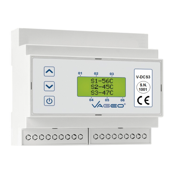
- Page 5 Display first start: The device features a V-DCS3 backlit LCD 8 characters x 2 lines on a green background . Connecting the power supply device is going through a phase where starting and shown the first two screens se- quentially as shown in Figure 2 .
- Page 6 Symbolisms on the Screen: << AUX: OFF or ON >> as example on the screen 1, shows the state of the controller checks whether or not the auxiliary source for DHW applications 2 & 3. << Error >> like the example on the screen 2 means damage to the sensor.
-
Page 7: Operation
Operation: The device V-DCS3 the time to be fed with electricity constantly performs checks proper func- tioning sensory outputs and relay contacts are available . The green screen background after 10 sec disappears , comes back with the click of one of the three buttons . - Page 8 Setup Menu: TABLE 1 Α/Α FROM Description of Parameters Abbreviation default Select Application ( See pages 3 & 4) . SYSTEM Higher Sink Temperature 20°C 95°C 80°C Maximum desired temperature heat sink . Differential Temperature Sensors 30°C 8°C Differential temperature S1-S2 ( for all applications ) and the S3-S2 ( only for application 4 ) which will trigger the R1 ( for all applications ) and the R2 ( only for application 4 ) respectively.
-
Page 9: Fault Diagnosis
Fault diagnosis: The device V-DCS3 the time to be fed with electricity, check the status of the sensors continu- ously. If any of the sensors has a problem or the cable is then cut on the screen shows the mes- sage <<...