Advertisement
Quick Links
Advertisement

Subscribe to Our Youtube Channel
Summary of Contents for NEONODE NNAMC2090PCEV
- Page 1 Neonode® Touch Sensor Module Get Started 2020-04-30...
-
Page 2: Table Of Contents
Neonode components are neither designed nor intended for use in FDA Class III applications, or similar life-critical medical equipment. Customers acknowledge and agree that they will not use any Neonode components in FDA Class III applications, or similar life-critical medical equipment, and that Neonode will not be responsible for any failure to meet the requirements of such applications or equipment. -
Page 3: Table Of Contents
Neonode® Touch Sensor Module User's Guide Table of Contents 1 Table of Contents Table of Contents ........................3 Getting started with Touch Sensor Module Evaluation............5 Getting Started with Sensor Evaluation - Plug and Play with USB Getting Started with Sensor Evaluation - Workbench and USB... -
Page 4: Getting Started With Touch Sensor Module Evaluation
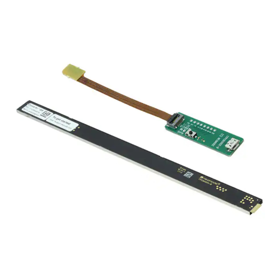
2.1 Getting Started with Sensor Evaluation - Plug and Play with USB 2.1.1 Required Equipment The following equipment from the evaluation kit is required: • 1 x Neonode Touch Sensor Module • 1 x FPC cable with connector • 1 x Interface board Additional required equipment: •... - Page 5 Neonode® Touch Sensor Module User's Guide Getting started with Touch Sensor Module Evaluation upwards. Make sure the direction is straight into the connector and the pads have reached the end of the connector. c. Make sure the connector pads of the FPC cable are facing downwards, towards interface board. The sensor module risks damage if the FPC cable is connected in wrong direction.
- Page 6 Neonode® Touch Sensor Module User's Guide Getting started with Touch Sensor Module Evaluation a. If the sensor module is of the 0° type: place the module on a table with the steel surface facing downwards and with the optical surface facing towards you.
-
Page 7: Getting Started With Sensor Evaluation - Workbench And Usb
2.2 Getting Started with Sensor Evaluation - Workbench and USB 2.2.1 Required Equipment The following equipment from the evaluation kit is required: • 1 x Neonode Touch Sensor Module • 1 x FPC cable with connector • 1 x Interface board Additional required equipment: •... - Page 8 Neonode® Touch Sensor Module User's Guide Getting started with Touch Sensor Module Evaluation • (Optional) tape for mounting 2.2.2 Connecting Sensor Module 1. Connect the FPC cable to the interface board: a. Lift the flip lock on the interface board.
- Page 9 Neonode® Touch Sensor Module User's Guide Getting started with Touch Sensor Module Evaluation 3. Connect a USB cable with a Micro USB type B connector to the interface board. 4. Make sure no object is within the touch active area of the sensor module before connecting power to the sensor through USB.
- Page 10 Neonode® Touch Sensor Module User's Guide Getting started with Touch Sensor Module Evaluation i. Alternatively, you can mount the sensor module by using tape in order to fasten the steel surface to the edge of a table, with the optical surface facing towards you.
- Page 11 Neonode® Touch Sensor Module User's Guide Getting started with Touch Sensor Module Evaluation 2. Unzip the installation package. 3. Open the installation package folder. 4. Run the Workbench installer (.msi file) and follow the instructions. 5. Open the installation package folder again.
- Page 12 Neonode® Touch Sensor Module User's Guide Getting started with Touch Sensor Module Evaluation 8. From the toolbar, select File >> Open Workspace. 9. Navigate to the Workspace folder and double-click the .nww file inside the folder. 2.2.4 Visualizing Touches with Workbench 1. In the left panel of the workspace, double-click zForce AIR Sensor Gadget Detection Visualizer. A tab with two sections, Control Panel and Tracking, opens in the right panel.
-
Page 13: Getting Started With Sensor Evaluation - I2C And Arduino
2.3 Getting Started with Sensor Evaluation - I2C and Arduino 2.3.1 Table of Contents • Required Equipment (see page 15) • Connecting Sensor Module using Interface Board (see page 15) • Connecting Sensor Module using Neonode Prototyping Board (see page 18) https://support.neonode.com/docs/display/Workbench/Getting+Started+with+Neonode+Workbench https://support.neonode.com ... - Page 14 2.3.2 Required Equipment Required Equipment using Interface Board 2.3.3 The following equipment from the evaluation kit is required: • 1 x Neonode Touch Sensor Module • 1 x FPC cable with connector • 1 x Interface Board Additional required equipment: •...
- Page 15 Neonode® Touch Sensor Module User's Guide Getting started with Touch Sensor Module Evaluation upwards. Make sure the direction is straight into the connector and the pads have reached the end of the connector. c. Make sure the connector pads of the FPC cable are facing downwards, towards interface board. The sensor module risks damage if the FPC cable is connected in wrong direction.
- Page 16 Neonode® Touch Sensor Module User's Guide Getting started with Touch Sensor Module Evaluation a. If the sensor module is of the 0° type: place the module on a table with the steel surface facing downwards and with the optical surface facing towards you.
- Page 17 Getting started with Touch Sensor Module Evaluation 6. The green LED on the interface board lights up when connected. 2.3.5 Connecting Sensor Module using Neonode Prototyping Board Evaluate Touch Sensor Module using Prototyping Board 1. Connect the sensor Module to the Prototyping Board a.
- Page 18 Neonode® Touch Sensor Module User's Guide Getting started with Touch Sensor Module Evaluation 2. The sensor module is now connected to the board, which expose all connections between the sensor module and the board. For details, refer to Electrical Integration . Do not connect power until the following steps have been performed.
-
Page 19: Getting Started With Sensor Evaluation - Sdk And Usb
2.4 Getting Started with Sensor Evaluation - SDK and USB 2.4.1 Required Equipment The following equipment from the evaluation kit is required: • 1 x Neonode Touch Sensor Module • 1 x FPC cable with connector • 1 x Interface board Additional required equipment: •... - Page 20 Neonode® Touch Sensor Module User's Guide Getting started with Touch Sensor Module Evaluation 2.4.2 Connecting Sensor 1. Connect the FPC cable to the interface board: a. Lift the flip lock on the interface board. b. Insert the FPC cable into the end of the connector, with the connector pads facing down, towards interface board.
- Page 21 Neonode® Touch Sensor Module User's Guide Getting started with Touch Sensor Module Evaluation 3. Connect a USB cable with a Micro USB type B connector to the interface board. Make sure no object is within the touch active area of the sensor module before connecting power to the sensor through USB.
- Page 22 Neonode® Touch Sensor Module User's Guide Getting started with Touch Sensor Module Evaluation i. Alternatively, you can mount the sensor module by using tape in order to fasten the steel surface to the edge of a table, with the optical surface facing towards you.
Need help?
Do you have a question about the NNAMC2090PCEV and is the answer not in the manual?
Questions and answers