Table of Contents
Advertisement
Available languages
Available languages
Advertisement
Table of Contents

Related Manuals for Festo DPA CRVZS Series


Summary of Contents for Festo DPA CRVZS Series
- Page 1 Druckbooster−Kombination Pressure booster combination DPA−...−CRVZS (de) Bedienungs− anleitung (en) Operating instructions (es) Instrucciones de utilización (fr) Notice d’utilisation (it) Istruzioni per l’uso (sv) Bruksanvisning 711 629 0806N H...
- Page 2 ..........Festo DPA−...−CRVZS 0806NH...
-
Page 3: Bedienteile Und Anschlüsse
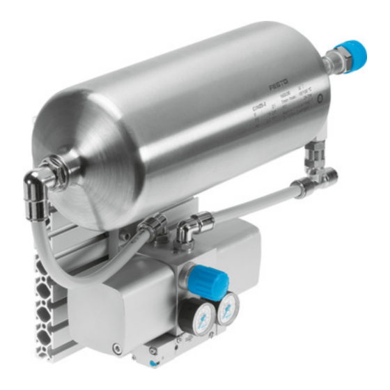
Manometerset (P1 Eingangsdruck, P2 Aus gangsdruck) Verbindungsleitung CRVZS zum Anschluss 2 Druckbooster DPA Reglerknopf für Ausgangsdruck Druckbooster DPA Pneumatischer Anschluss P1 (Eingang P Bypass Pneumatikventil mit Handhilfsbetätigung Pneumatischer Anschluss P2 (Ausgang Adapterplatte mit Schalldämpfern Profilplatte Bild 1 Festo DPA−...−CRVZS 0806NH Deutsch... -
Page 4: Funktion Und Anwendung
DPA selbsttätig an. Ein Pneumatikventil leitet den Eingangsdruck, der konstant am pneumatischen Anschluss P1 ansteht, wechselseitig in zwei Kompressions kammern (Doppelkolben−Druckübersetzung). Die Kompressionskammern er zeugen einen Ausgangsdruck bis max. dem doppelten Wert des Eingangs drucks. Bei Erreichen des eingestellten Ausgangsdrucks stellt der DPA seinen Festo DPA−...−CRVZS 0806NH Deutsch... -
Page 5: Voraussetzungen Für Den Produkteinsatz
Beachten Sie die Warnungen und Hinweise am Produkt und in dieser Bedie nungsanleitung. Beachten Sie die Vorschriften der Berufsgenossenschaft, des Technischen Überwachungsvereins oder entsprechende internationale Bestimmungen (z.B. Sicherheitsvorschriften nach EN 1012−1). Sorgen Sie für Druckluft mit ordnungsgemäßer Aufbereitung. Festo DPA−...−CRVZS 0806NH Deutsch... -
Page 6: Transport Und Lagerung
S Verwenden Sie den Reglerknopf nicht als Transporthalterung. Der Regler knopf kann sich aufgrund der großen Masse vom Sitz lösen. Einbau Vor dem Einbau: Entfernen Sie die Gummipuffer auf der Unterseite der Profilplatte. Schalten Sie Ihre gesamte Anlage drucklos. Festo DPA−...−CRVZS 0806NH Deutsch... - Page 7 Kantenabdeckung für Profilplatte IPM−AN−05−20X40−PA Zylinderschrauben M5 (Festigkeit min. 8.8, Schraubenlänge: Gestelldicke + 6 mm Einschraubtiefe. Anziehdrehmoment 5 Nm " 10 %) Wählen Sie das geeignete Zubehör aus dem Katalog www.festo.com/catalogue Einbau pneumatisch Hinweis Je höher die Druckdifferenz zwischen P1 und P2, desto höher der Eigenluftver brauch.
- Page 8 DPA−...−CRVZS Reglersicherung LRVS−D−MINI, LRVS−D−MIDI Bügelschloss LRVS−D Wählen Sie das geeignete Zubehör aus dem Katalog www.festo.com/catalogue Bei Verwendung eines Druckaufbauventils in der Anlage (è Bild 4): 1. Schließen Sie an der Eingangsseite vor P1 zwischen Druckaufbauventil und Druckbooster ein 3−Wege−Einschaltventil HE− −D oder HEE− −D an.
- Page 9 2. Öffnen Sie das 3−Wege−Einschaltventil an der Eingangsseite P1. 3. Öffnen Sie das 3−Wege−Einschaltventil an der Ausgangsseite P2. Druckluftausgang Kuppeln und Entkuppeln Vor Kupplung und Entkupplung von Anschlussleitungen am Ausgang P2: Reduzieren Sie den Ausgangsdruck auf max. 10 bar. Festo DPA−...−CRVZS 0806NH Deutsch...
- Page 10 4. Drehen Sie den Reglerknopf im Uhrzeigersinn bis der gewünschte Ausgangs druck am Manometer angezeigt wird (è Bild 1). Manometer P1: Eingangsdruck Manometer P2: Ausgangsdruck 5. Nur DPA−63(100)−10− : Drücken Sie den Drehknopf in Richtung Gehäuse. Der Reglerknopf ist nun verriegelt. Festo DPA−...−CRVZS 0806NH Deutsch...
- Page 11 1. Schließen Sie das 3−Wege−Einschaltventil an der Ausgangsseite P2. 2. Schließen Sie das 3−Wege−Einschaltventil an der Eingangsseite P1. Die Entlüftung erfolgt über die beiden Einschaltventile. Der Regler bleibt in der eingestellten Position. Druckluftspeicher entlüften Schließen Sie das 3−Wege−Einschaltventil zwischen Druckbooster DPA und Druckluftspeicher CRVZS. Festo DPA−...−CRVZS 0806NH Deutsch...
-
Page 12: Wartung Und Pflege
Wenn der Druckbooster bei verschlossenem Ausgang P2 ständig läuft: 1. Führen Sie eine Leckagemessung durch. 2. Ziehen Sie gelockerte Verschraubungen nach. Bei interner Leckage: Tauschen Sie das Produkt aus. Kondensat entleeren Entleeren Sie gelegentlich das Kondensat aus dem Druckluftspeicher. Bei DPA− −CRVZS2: Festo DPA−...−CRVZS 0806NH Deutsch... - Page 13 Druckluftspeicher CRVZS (è Bild 5). 4. Drehen Sie den Reglerknopf bis zum Anschlag gegen den Uhrzeigersinn. 5. Schalten Sie die Anlage drucklos. Beachten Sie dabei die Anzeige an den Manometern. 6. Trennen Sie die pneumatischen Anschlüsse. Störungsbeseitigung Festo DPA−...−CRVZS 0806NH Deutsch...
- Page 14 Handhabung aus. trolle Hörbare Leckage Dichtungen, Schläuche, Ven 1. Tauschen Sie das fehler tile oder Kupplungsdose de hafte Anschlussteil aus. fekt 2. Tauschen Sie das Produkt aus. Korrosion Aggressive Umgebungsbedin Tauschen Sie das Produkt gungen aus. Festo DPA−...−CRVZS 0806NH Deutsch...
-
Page 15: Technische Daten
Einstufung in Kate Gute Inge gorie nieurspra Werkstoff Druckluft hochlegierter Stahl, rostfrei speicher Gewicht [kg] 21,5 30,0 Aufgrund produktionsbedingter Streuung der Reglerfedern können bis zu 14 bar erreicht werden. Durch Luftverbrauch werden max. 15,5 bar erreicht. Festo DPA−...−CRVZS 0806NH Deutsch... - Page 16 DPA−...−CRVZS Festo DPA−...−CRVZS 0806NH Deutsch...
-
Page 17: Pressure Booster
Connecting tubing CRVZS to connection 2 of pressure booster DPA Regulator button for output pressure Pressure booster DPA Pneumatic connection P1 (input P Bypass Pneumatic valve with manual override Pneumatic connection P2 (output P Adapter plate with silencers Profile plate Fig. 1 Festo DPA−...−CRVZS 0806NH English... -
Page 18: Product Identification
When the set output pressure is reached, the pressure booster stops operating, but restarts automatically as soon as the output pressure drops due to application operation. Festo DPA−...−CRVZS 0806NH English... -
Page 19: Conditions Of Use
Observe the maximum values specified in these operating instructions. Note the warnings and instructions on the product and in the relevant operat ing instructions. Please comply with national and local safety laws and regulations (e.g. Safety regulations as per EN 1012−1). Festo DPA−...−CRVZS 0806NH English... -
Page 20: Transport And Storage
S Do not use the regulator button as a transport support. On account of the large mass, the regulator button may be loosened. Fitting Before fitting: Remove the rubber buffers on the bottom of the profile plate. Switch the complete system into a pressureless state. Festo DPA−...−CRVZS 0806NH English... - Page 21 IPM−AN−05−20X40−PA socket head screws M5 (strength min. 8.8, screw length: Stand thickness + 6 mm screw−in depth. Tightening torque 5 Nm " 10 %) Select suitable accessories from the catalogue www.festo.com/catalogue Fitting pneumatic components Note The greater the pressure difference between P1 and P2, the higher the internal air consumption.
- Page 22 LRVS−D−MINI, LRVS−D−MIDI padlock LRVS−D Select suitable accessories from the catalogue www.festo.com/catalogue If you are using a soft−start valve in the system (è Fig. 4): 1. Connect a 3−way start−up valve type HE− −D or HEE− −D to the input side in front of P1 between the soft−start valve and the pressure booster.
- Page 23 3. Open the 3−way start−up valve on the output side P2. Coupling and decoupling the compressed air output Before coupling or uncoupling connecting tubing at output P2: Reduce the output pressure to max. 10 bar. You then reduce the necessary force required. Festo DPA−...−CRVZS 0806NH English...
- Page 24 (è Fig. 1). Pressure gauge P1: Supply pressure Pressure gauge P2: Output pressure 5. Only DPA−63(100)−10− : Turn the rotary knob in the direction of the housing. The regulator button is now locked. Festo DPA−...−CRVZS 0806NH English...
- Page 25 2. Close the 3−way start−up valve on the input side P1. The exhaust procedure is performed using both start−up valves. The regulator remains in the set position. Exhausting the air reservoir Close the 3−way start−up valve between the pressure booster DPA and the air reservoir CRVZS. Festo DPA−...−CRVZS 0806NH English...
-
Page 26: Care And Maintenance
The pressure booster must start again automatically until the set output pres sure is reached. If the pressure booster runs continuously with output P2 closed: 1. Carry out a leakage check. 2. Tighten loose screw connectors. If there is internal leakage: Replace the device. Festo DPA−...−CRVZS 0806NH English... - Page 27 4. Turn the regulator button in an anti−clockwise direction as far as possible. 5. Switch the complete system into a pressureless state. When doing this note the display on the pressure gauges. 6. Loosen the pneumatic connections. Festo DPA−...−CRVZS 0806NH English...
-
Page 28: Eliminating Faults
Incorrect fitting or handling Replace the device. after visual inspec tion Audible leakage Seals, tubing, valves or quick 1. Replace the faulty coupling socket defective connecting part. 2. Replace the device. Corrosion Aggressive ambient condi Replace the device. tions Festo DPA−...−CRVZS 0806NH English... -
Page 29: Technical Specifications
Air reservoir material: High−alloy steel, stainless Weight [kg] 21.5 30.0 Due to scattering of the regulator springs during production up to 14 bar can be reached. Due to air consumption max. 15.5 bar are reached. Festo DPA−...−CRVZS 0806NH English... - Page 30 DPA−...−CRVZS Festo DPA−...−CRVZS 0806NH English...
-
Page 31: Elementos De Mando Y Conexiones
Botón regulador para la presión de salida Intensificador de presión DPA Conexión neumática P1 (entrada P Válvula de accionamiento neumático con Bypass accionamiento manual auxiliar Conexión neumática P2 (salida P Placa adaptadora con silenciadores Placa perfilada Fig. 1 Festo DPA−...−CRVZS 0806NH Español... -
Page 32: Identificación Del Producto
DPA se pone en marcha automáticamente. Una válvula de acciona miento neumático conduce la presión de entrada, la cual se mantiene cons tante en la conexión neumática P1, alternativamente a una y otra cámara de compresión (intensificación de presión de doble émbolo). Estas cámaras de Festo DPA−...−CRVZS 0806NH Español... - Page 33 Observe las advertencias e instrucciones en el producto y en estas instruccio nes de funcionamiento. Respete las directivas de los organismos profesionales, las reglamentaciones técnicas o las normas internacionales imperantes (p. ej. normas de seguridad según EN 1012−1). Festo DPA−...−CRVZS 0806NH Español...
-
Page 34: Transporte Y Almacenamiento
S No utilice el botón regulador como soporte para el transporte. El botón regu lador podría soltarse debido al elevado peso del conjunto. Instalación Antes de la instalación: Retire el amortiguador de goma situado sobre el lado inferior de la placa perfi lada. Desconecte completamente la instalación. Festo DPA−...−CRVZS 0806NH Español... - Page 35 Cubierta de bordes para la placa perfilada IPM−AN−05−20X40−PA Tornillos allen M5 (resistencia mín. 8.8, longitud de tornillo: espesor de bastidor + 6 mm profundidad de atornillado. Par de apriete 5 Nm " 10 %) Seleccione de nuestro catálogo el accesorio apropiado en www.festo.com/catalogue Instalación neumática Importante: Cuanto mayor es la diferencia de presión entre P1 y P2, mayor es el consumo...
- Page 36 Bloqueo del regulador LRVS−D−MINI, LRVS−D−MIDI Candado LRVS−D Seleccione de nuestro catálogo el accesorio apropiado en www.festo.com/catalogue Si se utiliza una válvula de arranque progresivo en la instalación (è Fig. 4): 1. Conecte en el lado de entrada ante P1, entre la válvula de arranque progresivo y el intensificador de presión, una válvula de cierre de 3 vías HE−...
-
Page 37: Puesta En Funcionamiento
3. Abra la válvula de cierre de 3 vías en el lado de salida P2. Acoplamiento y desacoplamiento de la salida de presión Antes de acoplar y desacoplar los tubos de conexión en la salida P2: Reduzca la presión de salida a un máximo de 10 bar. Festo DPA−...−CRVZS 0806NH Español... - Page 38 (è Fig. 1). Manómetro P1: Presión de entrada Manómetro P2: Presión de salida 5. Sólo DPA−63(100)−10− : Presione el botón giratorio en dirección al cuerpo. Ahora, el botón regulador está bloqueado. Festo DPA−...−CRVZS 0806NH Español...
- Page 39 El escape de aire se efectúa mediante las dos válvulas de cierre. El regulador permanece en la posición ajustada. Purga del acumulador de aire comprimido Cierre la válvula de cierre de 3 vías entre el intensificador de presión DPA y el acumulador de aire comprimido CRVZS. Festo DPA−...−CRVZS 0806NH Español...
- Page 40 Si el intensificador de presión funciona constantemente con la salida P2 cerrada: 1. Realice una medición de fugas. 2. Reapriete los racores flojos. En caso de fugas internas: Reemplace el producto. Festo DPA−...−CRVZS 0806NH Español...
- Page 41 CRVZS (è Fig. 5). 4. Haga girar el botón regulador hasta el tope en sentido contrario de las agujas del reloj. 5. Desconecte la instalación. Observe la indicación de los manómetros. 6. Separe las conexiones neumáticas. Festo DPA−...−CRVZS 0806NH Español...
-
Page 42: Eliminación De Fallos
Montaje o manejo incorrecto. Reemplace el producto. el control visual Fugas audibles. Juntas, tubos flexibles, 1. Substituya la pieza de válvulas o acoplamientos unión defectuosa. averiados. 2. Reemplace el producto. Corrosión. Condiciones ambientales Reemplace el producto. agresivas. Festo DPA−...−CRVZS 0806NH Español... -
Page 43: Datos Técnicos
Peso [kg] 21,5 30,0 Debido a las tolerancias de fabricación de los muelles de los reguladores pueden alcanzarse hasta 14 bar. Debido al consumo de aire se alcanzan como máximo 15,5 bar. Festo DPA−...−CRVZS 0806NH Español... - Page 44 DPA−...−CRVZS Festo DPA−...−CRVZS 0806NH Español...
-
Page 45: Eléments De Commande Et Raccordements
DPA Bouton de réglage de la pression de sortie Surpresseur DPA Raccordement pneumatique P1 (entrée P Distributeur pneumatique à commande By−pass manuelle auxiliaire Raccordement pneumatique P2 Plaque d’adaptation insonorisée (sortie P Plaque profilée Fig. 1 Festo DPA−...−CRVZS 0806NH Français... -
Page 46: Identification Du Produit
P1, en alternance vers deux chambres de compression (transmission de pression à double piston). Ces dernières génèrent une pression de sortie attei gnant au maximum le double de la pression d’alimentation. Lorsque la pression de Festo DPA−...−CRVZS 0806NH Français... - Page 47 Respectez les avertissements et indications apposés sur le produit et indiqués dans la présente notice d’utilisation. Respectez les prescriptions des organismes professionnels et des services de contrôle technique, et les réglementations internationales en vigueur (p. ex. directives de sécurité selon la norme EN 1012−1). Festo DPA−...−CRVZS 0806NH Français...
-
Page 48: Transport Et Stockage
S N’utilisez pas le bouton de réglage comme support de transport, car il pour rait sortir de son logement en raison de l’importance de la masse. Montage Avant le montage : Retirez les supports en caoutchouc situés sous la plaque profilée. Coupez la pression dans toute l’installation. Festo DPA−...−CRVZS 0806NH Français... - Page 49 S Raccordez la pression réseau de 8 bars max. au côté entrée de P1 sans mano détendeur additionnel. Raccordez les tuyaux et les raccords enfi Fig. 3 chables aux raccordements pneumatiques P1 et P2 (è Fig. 3). L’échappement s’effectue par le régula teur. Festo DPA−...−CRVZS 0806NH Français...
- Page 50 3. Raccordez un troisième distributeur de mise en circuit trois voies HE− −D ou HEE− −D supplémentaire entre le surpresseur DPA et l’accumulateur pneuma tique CRVZS. Il est ainsi possible de purger plus rapidement de gros volumes de réservoirs. Fig. 5 Festo DPA−...−CRVZS 0806NH Français...
-
Page 51: Mise En Service
3. Ouvrez le distributeur de mise en circuit 3 voies du côté sortie P2. Accoupler et désaccoupler la sortie d’air comprimé. Avant d’accoupler et de désaccoupler les conduites de raccordement sur la sortie P2 : Réduisez la pression de sortie à 10 bars maximum. Festo DPA−...−CRVZS 0806NH Français... - Page 52 (è Fig. 1). Manomètre P1 : Pression d’alimentation Manomètre P2 : Pression de sortie 5. DPA−63(100)−10− uniquement : Enfoncez le bouton de réglage vers le boîtier. Le bouton de réglage est ainsi verrouillé. Festo DPA−...−CRVZS 0806NH Français...
- Page 53 1. Fermez le distributeur de mise en circuit 3 voies du côté sortie P2. 2. Fermez le distributeur de mise en circuit 3 voies du côté entrée P1. L’échappement s’effectue par les deux distributeurs de mise en circuit. Le régulateur reste dans la position réglée. Festo DPA−...−CRVZS 0806NH Français...
-
Page 54: Maintenance Et Entretien
Lorsque le surpresseur fonctionne en continu alors que la sortie P2 est fermée : 1. Effectuez une mesure de fuites. 2. Resserrez les raccords desserrés Dans le cas de fuites internes : Remplacez le produit. Festo DPA−...−CRVZS 0806NH Français... - Page 55 CRVZS (è Fig. 5). 4. Faites tourner le bouton de réglage dans le sens antihoraire jusqu’en butée. 5. Coupez la pression dans l’installation. Observez l’affichage sur le manomètre pendant cette opération. 6. Débranchez les raccordements pneumatiques. Festo DPA−...−CRVZS 0806NH Français...
-
Page 56: Dépannage
Remplacez le produit. rieure après contrôle conformes visuel Fuites audibles Joints, tuyaux, distributeurs 1. Remplacez la pièce de ou coupleur rapide défec raccordement défectueuse. tueux 2. Remplacez le produit. Corrosion Conditions ambiantes Remplacez le produit. agressives Festo DPA−...−CRVZS 0806NH Français... -
Page 57: Caractéristiques Techniques
Poids [kg] 21,5 30,0 En raison de la dispersion des ressorts de régulateurs due à la production, il est possible d’atteindre 14 bars. En raison de la consommation d’air, il est seulement possible d’obtenir 15,5 bars max. Festo DPA−...−CRVZS 0806NH Français... - Page 58 DPA−...−CRVZS Festo DPA−...−CRVZS 0806NH Français...
- Page 59 2 del moltiplicatore di pressione DPA Manopola del regolatore per pressione d’uscita Moltiplicatore di pressione DPA Collegamento pneumatico P1 (ingresso P Valvola pneumatica con azionatore manuale Bypass Piastra d’adattamento con silenziatori Collegamento pneumatico P2 (uscita P Piastra profilata Fig. 1 Festo DPA−...−CRVZS 0806NH Italiano...
-
Page 60: Identificazione Del Prodotto
DPA si avvia automaticamente. Una valvola pneumatica introduce la pressione di alimentazione che viene applicata costantemente all’attacco pneumatico P1, alternativamente nelle due camere del compressore (moltipli cazione di pressione a doppio pistone). Queste camere di compressione Festo DPA−...−CRVZS 0806NH Italiano... -
Page 61: Presupposti Per L'impiego Del Prodotto
Osservare le avvertenze e le note riportate sul prodotto e in queste istruzioni per l’uso. Rispettare le norme dell’associazione di categoria, del TÜV o eventuali regolamenti internazionali equivalenti (ad es. disposizioni di sicurezza della norma EN 1012−1). Provvedere a una preparazione corretta dell’aria compressa. Festo DPA−...−CRVZS 0806NH Italiano... -
Page 62: Trasporto E Magazzinaggio
S Non utilizzare la manopola del regolatore come supporto per il trasporto. Per effetto dell’elevata massa, la manopola del regolatore si potrebbe stac care dal supporto. Montaggio Prima del montaggio: Rimuovere i paracolpi di gomma sul lato inferiore della piastra profilata. Scollegare la pressione dall’intero impianto. Festo DPA−...−CRVZS 0806NH Italiano... - Page 63 Coprispigoli per piastra profilata IPM−AN−05−20X40−PA Viti cilindriche M5 (solidità min. 8.8, lunghezza viti: spessore telaio + 6 mm pro fondità di avvitamento. Coppia di serraggio 5 Nm " 10 %) Selezionare gli accessori adeguati dal catalogo www.festo.com/catalogue Montaggio delle parti pneumatiche Nota Maggiore è...
- Page 64 Blocco regolatore LRVS−D−MINI, LRVS−D−MIDI Lucchetto LRVS−D Selezionare gli accessori adeguati dal catalogo www.festo.com/catalogue In caso di utilizzo di una valvola di inserimento progressivo nell’impianto (è Fig. 4): 1. Sul lato di ingresso a monte di P1 tra valvola di inserimento progressivo e moltipli catore di pressione collegare una valvola di inserimento a 3 vie HE−...
-
Page 65: Messa In Servizio
3. Aprire la valvola di inserimento a 3 vie sul lato di uscita P2. Accoppiamento e disaccoppiamento dell’uscita aria compressa Prima di accoppiare o disaccoppiare le linee di collegamento sull’uscita P2: Ridurre la pressione d’uscita a max. 10 bar. Festo DPA−...−CRVZS 0806NH Italiano... - Page 66 4. Girare la manopola del regolatore in senso orario finché sul manometro non appare la pressione d’uscita richiesta (è Fig. 1). Manometro P1: Pressione di alimentazione Manometro P2: Pressione d’uscita 5. Solo DPA−63(100)−10− : premere la manopola in direzione del corpo. Ora la manopola del regolatore è bloccata. Festo DPA−...−CRVZS 0806NH Italiano...
- Page 67 Lo scarico avviene tramite le due valvole di inserimento. Il regolatore rimane nella posizione impostata. Sfiato del serbatoio per aria compressa Chiudere la valvola di inserimento a 3 vie tra moltiplicatore di pressione combi nato DPA e serbatoio per aria compressa CRVZS. Festo DPA−...−CRVZS 0806NH Italiano...
-
Page 68: Manutenzione E Cura
Il moltiplicatore di pressione deve riavviarsi da solo finché non è stata raggiunta la pressione d’uscita impostata. Quando il moltiplicatore di pressione funziona in modo continuo con l’uscita P2 chiusa: 1. Eseguire un rilevamento delle perdite. 2. Serrare i raccordi allentati. In caso di perdita interna: Sostituire il prodotto. Festo DPA−...−CRVZS 0806NH Italiano... - Page 69 3. Chiudere la valvola di inserimento a 3 vie tra moltiplicatore di pressione DPA e serbatoio per aria compressa CRVZS (è Fig. 5). 4. Girare la manopola del regolatore in senso antiorario fino all’arresto meccanico. 5. Disinserire la pressione dall’impianto. Osservare l’indicatore sui manometri. 6. Staccare gli attacchi pneumatici. Festo DPA−...−CRVZS 0806NH Italiano...
-
Page 70: Eliminazione Dei Guasti
Sostituire il prodotto. durante l’ispezione visiva Perdita udibile Guarnizioni, tubi flessibili, val 1. Sostituire il pezzo di at vole o connettore femmina di tacco difettoso. fettosi 2. Sostituire il prodotto. Corrosione Condizioni ambientali aggres Sostituire il prodotto. sive Festo DPA−...−CRVZS 0806NH Italiano... -
Page 71: Dati Tecnici
Peso [kg] 21,5 30,0 Per effetto della deviazione delle molle del regolatore condizionata dal prodotto possono essere raggiunti fino a 14 bar. Per effetto del consumo d’aria vengono raggiunti max. 15,5 bar. Festo DPA−...−CRVZS 0806NH Italiano... - Page 72 DPA−...−CRVZS Festo DPA−...−CRVZS 0806NH Italiano...
- Page 73 P2 utgångstryck) Anslutning mellan CRVZS och anslutning 2 på tryckstegrare DPA Regulatorratt för utgångstryck Tryckstegrare DPA Pneumatisk anslutning P1 (ingång P Bypass Pneumatikventil med manuell manövrering Pneumatisk anslutning P2 (utgång P Adapterplatta med ljuddämpare Profilplatta Bild 1 Festo DPA−...−CRVZS 0806NH Svenska...
-
Page 74: Funktion Och Användning
P1, växelvis till två kompressionskammare (dubbelkolv− strycköverföring). Dessa skapar ett utgångstryck upp till max. det dubbla värdet av ingångstrycket. När det inställda utgångstrycket har uppnåtts, stannar DPA och startar automatiskt igen när utgångstrycket sjunker. Festo DPA−...−CRVZS 0806NH Svenska... - Page 75 S Se till att nedanstående anvisningar alltid följs. Beakta gränsvärdena i denna bruksanvisning. Beakta varningarna och informationen på produkten och i den här bruksanvisningen. Följ gällande lagar och förordningar (t.ex. säkerhetsföreskrifter enligt EN 1012−1). Se till att tryckluften förbehandlas korrekt. Festo DPA−...−CRVZS 0806NH Svenska...
-
Page 76: Transport Och Lagring
S Ta hänsyn till produktens vikt. Beroende på utförande väger DPA− −CRVZS upp till 30 kg. S Använd inte regulatorratten som transporthandtag. Regulatorratten kan lossna på grund av för stor massa. Montering Före monteringen: Ta bort gummibufferten på profilplattans undersida. Gör hela anläggningen trycklös. Festo DPA−...−CRVZS 0806NH Svenska... - Page 77 IPM−AN−05−20X40−PA cylinderskruvar M5 (hållfasthet min. 8.8, skruvlängd: stativtjocklek + 6 mm inskruvningsdjup. Åtdragningsmoment 5 Nm " 10 %) Välj tillbehör ur katalogen www.festo.com/catalogue Pneumatisk montering Information Ju högre tryckdifferensen är mellan P1 och P2, desto högre är egenförbrukningen.
- Page 78 DPA−...−CRVZS regulatorspärr LRVS−D−MINI, LRVS−D−MIDI hänglås LRVS−D Välj tillbehör ur katalogen www.festo.com/catalogue Om en mjukstartsventil används i anläggningen (è Bild 4): 1. Anslut en 3−vägs−avstängningsventil HE− −D eller HEE− −D på ingångssidan före P1, mellan mjukstartsventil och tryckstegrare. 2. Anslut en 3−vägs−avstängningsventil HE− −D eller HEE− −D på utgångssidan efter P2.
- Page 79 3−vägs−avstängningsventilen skall vara öppen under drift. 2. Öppna 3−vägs−avstängningsventilen på ingångssidan P1. 3. Öppna 3−vägs−avstängningsventilen på utgångssidan P2. Tryckluftsutgång in− och urkoppling Före koppling och frånkoppling av anslutningskablar på utgång P2: Reducera utgångstrycket till max. 10 bar. Festo DPA−...−CRVZS 0806NH Svenska...
- Page 80 S Differenstrycket mellan P1 och P2 ska minst vara 2 bar. 4. Vrid regulatorknappen medurs tills önskat utgångstryck visas på manometern (è Bild 1). Manometer P1: Ingångstryck Manometer P2: Utgångstryck 5. Endast DPA−63(100)−10− : Tryck regulatorratten mot huset. Regulatorknappen är nu spärrad. Festo DPA−...−CRVZS 0806NH Svenska...
- Page 81 Vid tryckstegrarkombinationer DPA− −CRVZS10(20) (è Bild 5): 1. Stäng 3−vägs−avstängningsventilen på utgångssidan P2. 2. Stäng 3−vägs−avstängningsventilen på ingångssidan P1. Avluftningen sker via båda avstängningsventilerna. Regulatorn står kvar på inställd position. Avlufta tryckluftsbehållaren Stäng 3−vägs−avstängningsventilen mellan tryckstegraren DPA och tryckluftsbehållaren CRVZS. Festo DPA−...−CRVZS 0806NH Svenska...
-
Page 82: Underhåll Och Skötsel
Tryckstegraren måste starta om automatiskt tills det inställda utgångstrycket har uppnåtts. Om tryckstegraren ständigt går när utgång P2 är stängd: 1. Genomför en läckagemätning. 2. Dra åt skruvkopplingar som lossnat. Vid internt läckage: Byt ut produkten. Festo DPA−...−CRVZS 0806NH Svenska... - Page 83 1. Stäng 3−vägs−avstängningsventilen på utgångssidan P2. 2. Stäng 3−vägs−avstängningsventilen på ingångssidan P1. 3. Stäng 3−vägs−avstängningsventilen mellan tryckstegraren DPA och tryckluftsbehållaren CRVZS (è Bild 5). 4. Vrid regulatorratten moturs till anslag. 5. Avlufta anläggningen. Beakta manometerindikeringen. 6. Lossa de pneumatiska anslutningarna. Festo DPA−...−CRVZS 0806NH Svenska...
-
Page 84: Åtgärdande Av Störningar
Yttre skador enligt Felaktig montering eller Byt ut produkten. okulärbesiktning hantering Hörbart läckage Tätningar, slangar, ventiler 1. Byt ut den felaktiga eller kopplingsdosa defekta anslutningsdelen. 2. Byt ut produkten. Korrosion Aggressiv omgivning Byt ut produkten. Festo DPA−...−CRVZS 0806NH Svenska... -
Page 85: Tekniska Data
Indelning i kategori God ingen− jörspraxis Material trycklufts− höglegerat stål, rostfritt behållare Vikt [kg] 21,5 30,0 På grund av produktionsbetingad spridning av regulatorfjädrarna, kan upp till 14 bar uppnås. På grund av luftförbrukning nås max. 15,5 bar. Festo DPA−...−CRVZS 0806NH Svenska... - Page 86 DPA−...−CRVZS Festo DPA−...−CRVZS 0806NH Svenska...
- Page 87 DPA−...−CRVZS Festo DPA−...−CRVZS 0806NH...
- Page 88 Copyright: autorisation écrite expresse. Tout manquement à cette règle Festo AG & Co. KG est illicite et expose son auteur au versement de dommages Postfach 6040 et intérêts. Tous droits réservés pour le cas de la délivrance D−73726 Esslingen...
Need help?
Do you have a question about the DPA CRVZS Series and is the answer not in the manual?
Questions and answers