
Related Manuals for Campbell SDM-SIO1


Summary of Contents for Campbell SDM-SIO1
- Page 1 SDM-SIO1 Serial Input/Output Module Issued: 5.1.15 Copyright © 2006-2015 Campbell Scientific Ltd. CSL 627...
- Page 3 Quotations for repairs can be given on request. It is the policy of Campbell Scientific to protect the health of its employees and provide a safe working environment, in support of this policy a “Declaration of Hazardous Material and Decontamination”...
- Page 5 • Periodically (at least yearly) check electrical ground connections. WHILE EVERY ATTEMPT IS MADE TO EMBODY THE HIGHEST DEGREE OF SAFETY IN ALL CAMPBELL SCIENTIFIC PRODUCTS, THE CUSTOMER ASSUMES ALL RISK FROM ANY INJURY RESULTING FROM IMPROPER INSTALLATION, USE, OR MAINTENANCE OF TRIPODS, TOWERS, OR ATTACHMENTS TO TRIPODS AND TOWERS...
- Page 7 Campbell Scientific Ltd can advise on the recycling of the equipment and in some cases arrange collection and the correct disposal of it, although charges may apply for some items or territories.
-
Page 9: Table Of Contents
3. Installation ..............5 3.1 Connections ....................6 3.2 Safety considerations ................8 3.3 Examples for connecting the SDM-SIO1 to other equipment ....9 3.3.1 RS-485 one to one connection example ......... 9 3.3.2 RS-485 multi unit / in line example ..........10 3.3.3 RS-485 half duplex wiring example .......... - Page 10 A.2 The output pin (RTS/pin 9) ............A-2 Tables 3-1. SDM address settings ................6 3-2. SDM-SIO1 connections (left to right as viewed from the front of the unit) ....................7 3-3. SDM-SIO1 Functional description of the connections ......7 4-1.
-
Page 11: Introduction
Connections and programming for RS422 are otherwise identical to RS485. The SDM-SIO1 will accept serial data and store it in its buffer which is 2047 bytes in size allowing remote equipment to transmit large amounts of data without needing to stop other processes in the datalogger. -
Page 12: Specifications
The only difference in operation between the SDM-SIO1 and a built-in port is that there will be a small delay when transferring data to and from the device via the SDM connection (see Section 4.1). -
Page 13: Electrical Parameters
User Guide discarded until space is made when the logger requests data from the SDM-SIO1. 2.2 Electrical parameters 2.2.1 SDM-SIO1 current consumption Nominal Notes General currents Standby current 70 uA 100 uA Current after SerialClose has been called. RS-232 and RS-485 current consumption Idle current 5.5 mA... -
Page 14: Sdm-Sio1 Voltage Specifications
SDM lines (low level) 0.7V (1) Values are volts D.C. (except resistances) (2) It is NOT recommended that the user runs their SDM-SIO1 at maximum ratings for extended periods of time (3) Assuming a worst case 3 KΩ load (4) It is not recommended that the user allows such low input voltages as there will be an increased chance that external noise may cause errors in the incoming data 2.2.3 EMC compliance... -
Page 15: Physical Parameters
SDM addresses and their relationships to the COMport number in the SerialOpen command. There can be up to 15 SDM-SIO1s on a single SDM bus. Each SDM-SIO1 will need to be set to a unique address before they are powered up; if any other equipment is present on the bus, whether it’s an SDM-SIO1 or not, then the user... -
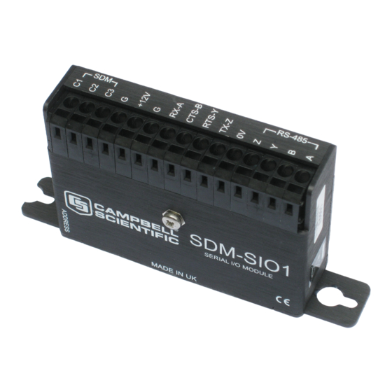
Page 16: Connections
When making connections to the datalogger always ensure power to the datalogger is switched off and connect the ground (G) connection first. Below is a table showing all the connections on the SDM-SIO1. There are a number of pins that are common within the unit, these are also shown below. -
Page 17: Sdm-Sio1 Connections (Left To Right As Viewed From The Front Of The Unit)
(see below) for the SDM-SIO1 relative to the device it is being used with as they give a more certain indicator of the correct connection than the A/B notation. -
Page 18: Safety Considerations
3.2 Safety considerations The SDM-SIO1 is considered to be a component of a measurement system that is installed in an enclosure and wired up in accordance with this manual. Due to space considerations full details of the maximum ratings of the connections are not given on the device. -
Page 19: Examples For Connecting The Sdm-Sio1 To Other Equipment
There is a current limiting resistor fitted in the 0V line in the SDM-SIO1, but this will not be adequate in the event of a serious ground fault, e.g. the ground references being 240 V apart, due to faulty AC wiring. -
Page 20: Rs-485 Multi Unit / In Line Example
SDM-SIO1 Serial Input/Output Module 3.3.2 RS-485 multi unit / in line example RS-485 0V for ground referencing . To logger +12V RS-485 0V First RS-485 equipment RX - A RS-485_ Y RS-485_ Z RS-485_ A * Not connection orde TX - Z... -
Page 21: Rs-485 Half Duplex Wiring Example
User Guide 3.3.3 RS-485 half duplex wiring example To logger +12V 100R or higher (Termination resistor may not be RX - A needed for many applications) CTS - B RTS - Y TX - Z RS-485 0V RS-485 equipment RS-485_B RS-485_A RS-485_Z RS-485_Y... -
Page 22: Rs-232 Wiring Example With Handshaking
SDM-SIO1 Serial Input/Output Module 3.3.5 RS-232 wiring example with handshaking To logger +12V RX - A RS-232_RX RS-232 DCE CTS - B RS-232 RTS equipment RS-232 CTS RTS - Y TX - Z RS-232 TX * Note CTS and RTS a re optional if hardware handshaking is not required. -
Page 23: Connecting A 9 Way Socket To The Sdm-Sio1
User Guide 3.3.7 Connecting a 9 way socket to the SDM-SIO1 To logger DTE configuration RS-232 9 way D - type connector +12V Pin 5 connector RX - A RS-232_TX Pin 3 CTS - B RS-232 CTS Pin 8 RTS - Y... -
Page 24: Programming The Datalogger
Serialclose (see below). When running in RS-232 mode with a sensor that only sends data one-way to the datalogger, run the SDM-SIO1 in “receive only mode” as this does not turn on the output drivers. -
Page 25: Communications Port Parameters Rs-232
User Guide SerialOpenFormat parameter This parameter defines not only the data format but with the SDM-SIO1 is used to set whether the module should work in normal RS-232, listen only RS-232, full or half-duplex RS-485 modes as defined in the tables below. -
Page 26: Serialclose
(1) This mode is only supported if there is at least a one bit delay between characters received by the SDM-SIO1 4.1.2 SerialClose This will place the SDM-SIO1 unit into shutdown mode where only SDM communications will operate. This means any data coming into the SDM-SIO1 on the RS-232/RS-485 interface will be lost. -
Page 27: Serialin
SDM-SIO1 to the logger in approximately 2.7 ms. Time = (10 + 1) * (8 * 30) Note: that 30µs per bit is the default data rate for most Campbell loggers. It is possible to reduce this time and the transfer time by using the SDMSpeed instruction. -
Page 28: Serialinchk
SDM-SIO1 Serial Input/Output Module 4.1.7 SerialInChk This returns the number of characters that have been received by the SDM-SIO1 and that are currently held in its buffer (0-2047). 4.1.8 SerialInRecord No special information. 4.1.9 SerialFlush This command will purge all information in the logger and SDM-SIO1 transmit and receive buffers. -
Page 29: Rs-485 Half-Duplex Mode
In receive only mode the SDM-SIO1 will consume less current than normal but still can receive new information on its RS-232 port. The example below will set the SDM-SIO1 with the address 0 into receive only mode. All normal baud rates and buffer sizes are supported. - Page 30 '----------------------------------------------------------------------- ' Example use of the SDM-SIO1. ' This example shows how to open the a serial port using an SDM-SIO1. ' A prompt is sent from the logger to the sensor and it then waits for a response ' before reading the data.
- Page 31 ' This example shows how to open the RS-485 serial port using an SDM-SIO1. ' Data is sent from the logger to the sensor. ' The program then sits in a loop until the SDM-SIO1 reports it had data ' available...
-
Page 32: Firmware Upgrades And Flash Signature Errors
At the end of the process a success message will be shown if successful. During the loading of the operating system do not disturb or disconnect power to the SDM-SIO1 otherwise it may need to be returned to the factory for repair. - Page 33 BeginProg SDMSpeed (30) ‘Fix the speed Ver_Value = "" Sig_Value = "" Scan(1,Sec,0,0) 'Use the generic SDM command to get extra info from the SDM-SIO1 'Ask for the firmware version Src = CHR(1) SDMGeneric(Ver_Value,SDM_Address,cmd,bytes_out,Src,Ver_values_in,bytes_val, big_endian,delay_usec) ' Read signature Src = CHR(2) SDMGeneric(Sig_Value,SDM_Address,cmd,bytes_out,Src,Sig_values_in,bytes_val,big_endian,delay_usec) Sig_Value_Dec = HexToDec (Sig_Value) 'Convert sig to decimal too.
-
Page 35: The Input Pin (Cts/Pin 8
The example below shows how to call the command with the required parameters. 'CR1000 Example program showing how to detect the state of the input line on an SDM-SIO1 'Using the SDMGeneric instruction... -
Page 36: The Output Pin (Rts/Pin 9
‘ This will set the spare output pin low SerialOutBlock(32, 0, 0) The two example lines of code above will set the output pin on the SDM-SIO1 high then low respectively on the SDM-SIO1 device set to address 0 on its rotary switch. - Page 38 CAMPBELL SCIENTIFIC COMPANIES Campbell Scientific, Inc. (CSI) 815 West 1800 North Logan, Utah 84321 UNITED STATES www.campbellsci.com info@campbellsci.com Campbell Scientific Africa Pty. Ltd. (CSAf) PO Box 2450 Somerset West 7129 SOUTH AFRICA www.csafrica.co.za sales@csafrica.co.za Campbell Scientific Australia Pty. Ltd. (CSA)
Need help?
Do you have a question about the SDM-SIO1 and is the answer not in the manual?
Questions and answers