Table of Contents
Advertisement
Quickstart document
HEIGHT GAUGES
for MICRO-HITE 2016 (MH 2016)
for MICRO-HITE+M 2016 (MH+M 2016)
This document is confidential and only to be used internally by the company that has purchased one of the height gauges
mentioned above. Before duplicating or transmitting it to third parties without any connection to the use of these instruments,
an official request has to be sent to TESA SA.
1
Advertisement
Table of Contents

Summary of Contents for TESA MICRO-HITE 2016
- Page 1 This document is confidential and only to be used internally by the company that has purchased one of the height gauges mentioned above. Before duplicating or transmitting it to third parties without any connection to the use of these instruments, an official request has to be sent to TESA SA.
-
Page 2: Table Of Contents
Quickstart document TABLE OF CONTENTS INTRODUCTION ................................3 Acknowledgements ..............................3 Warning ................................... 3 Copyright ................................. 3 Preamble ................................. 3 Symbols .................................. 4 PRESENTATION ................................5 General description ..............................5 INSTALLATION, SECURITY & MAINTENANCE ......................7 Location ................................... 7 Place of use ................................7 Lighting .................................. -
Page 3: Introduction
1.1 Acknowledge- Dear user, ments We would like to thank you for having chosen TESA as your metrology partner. We thank you for your confidence in purchasing one of our high-end height gauges from our MICRO-HITE or MICRO-HITE+M range. Your metrological concerns are important to us and we are convinced that this instrument will meet your expectations. -
Page 4: Symbols
Quickstart document 1.5 Symbols Several different types of symbols are used in this manual. They give important information that has to be taken into account in order to correctly use the measuring instrument. Position Description Not adhering to these instructions can lead to incorrect measurement results. -
Page 5: Presentation
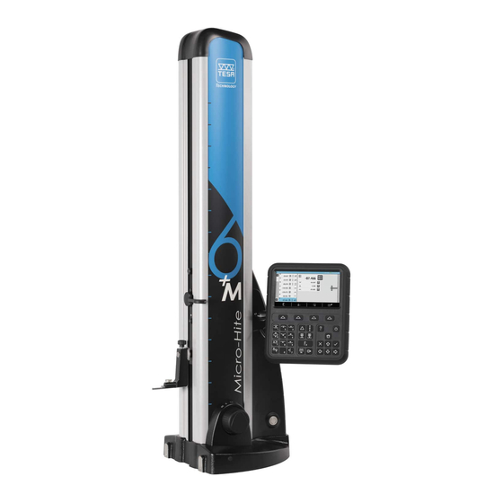
Quickstart document PRESENTATION 2.1 General description N° Description Cap cover Electronic system reading the position (sensor + scale) Fixing knob of the measuring carriage Handle for manual probe displacement Connector for accessory Information LED Probe support Probe Guiding and support faces Cast-iron base Rotary control handle or handwheel for displacement Electric pump... - Page 6 Quickstart document Fig. Description of the constitutive elements of the TESA MICRO-HITE+M...
-
Page 7: Installation, Security & Maintenance
INSTALLATION, SECURITY & MAINTENANCE 3.1 Location The instrument has to be installed in a location satisfying the general required conditions, but also the specific and very precise conditions regarding the environment, power supply, etc. It is essential to be able to identify important factors and to correctly prepare the zone the instrument is installed and used in. -
Page 8: Batteries
Recharging the batteries The batteries are only to be recharged with the charger provided with the height gauge (TESA reference: 00760245). Not adhering to this rule can cause irreversible damage to the instrument or its instability. 3.9 Final use The instrument is to be used for measurements only. -
Page 9: Installation
Each MICRO-HITE or MICRO-HITE+M instrument is delivered in packaging developed to protect it from shocks and corrosion. Only transport the height gauge in this packaging. Any other transport using unofficial packaging is not recommended and will not be covered by TESA in case of dispute. 4.2 Unpacking &... - Page 10 Quickstart document Remove the probe and its support from the box. Mount the probe on the support. Do not forget to tighten the assembly with the tightening wheel. Accessories are now ready to be used. Remove the top two protection foam pieces from the box. With a second person, take carefully the gage out of the box.
- Page 11 It is highly recommended not to do this step alone. Two persons are required to avoid any damage of the instrument in case of a shock or an uncontrolled movement. Because of the weight of the instrument, it is not recommended to lift the unit on your own.
- Page 12 Quickstart document This handle is used for manual fast displacement of the probe between two measurement zones. It is very fragile and no force whatsoever must be applied on it, except for the force applied for normal displacement during a measurement.
- Page 13 13 Install the instrument vertically on the clean granite plate (or any other support). 14 Remove the protective plastic cover. 15 Carefully remove the panel arm protection. 16 Carefully remove the protective tape from the base, the handle and the gage top’s cap.
- Page 14 Quickstart document 17 Remove the two screws from the front shipping bracket. 18 Carefully pull the plate off. 19 Carefully remove the shaft protection (where the probe holder is going to be mounted). 20 Mount the probe support and its probe on the shaft.
- Page 15 21 Remove the panel from its box. 22 Screw the control panel on the articulated support. Any cable connections have to be established while the instrument is turned off. Make sure that the instrument is turned off each time the control panel/height gauge cable is connected or disconnected.
- Page 16 Quickstart document 24 Make sure that the battery is correctly installed in the height gauge. 25 Connect the height gauge to a power source using the power supply unit for direct main operation or later use (with batteries once they are charged).
-
Page 17: Simplified User Manual
SIMPLIFIED USER MANUAL 5.1 Panel The control panel of your height gauge has been developed to enable an ideal navigation through its software and an intuitive use. Its keyboard is separated in four sets of keys that are easily distinguishable by their functionality. The control panel below is defined for motorised height gauges type MICRO-HITE+M. -
Page 18: Main Menu
Quickstart document The probe will have to be moved manually by the user in order to detect the reference mark. Once the mark is found, the instruments beeps and the software enters in ST1/ST2 mode or displays the main menu (user selection in system options). 5.4 Main menu Once the initialisation process has been performed, the software will display by default its main menu. -
Page 19: St1 & St2 Modes
N° Description Measurements’ list Status bar Main and secondary results of the last measure Help zone Contextual actions (options are displayed regarding the software active page and the action the user performs) N° Description Block title Label automatically created ... - Page 20 Quickstart document Mode Description Lengths measurement in only one probing direction. The calibration of the probe is not necessary. Lengths measurement in two probing directions. The calibration of the probe is mandatory. Measurement with one probing direction Measurement with two probing directions The access to ST1 mode does not require the determination of the probe constant.
-
Page 22: Contextual Actions
Quickstart document CONTEXTUAL ACTIONS 6.1 General actions Definition Cancel Allows you to cancel the current process or to leave a mode without saving any changes. Delete Allows you to delete the selected value. Return Allows to come back to the previous page. Cartesian coordinates Allows to work in Cartesian coordinates. -
Page 23: Actions Regarding St1 & St2 Modes
Change resolution 1 Allows you to increase the resolution of a graph (searching the culmination point) or to come back to measurement results’ global details (after a program recall) Change resolution 2 Allows you to decrease the resolution of a graph (searching the culmination point) or to access measurement results’... -
Page 24: Actions Regarding Min, Max, Δ Mode
Quickstart document Allows you to manually enter the size of the standard used in order to calculate the angle of a workpiece. This value is stored in the memory as long as the instrument is not turned off. 6.5 Actions regarding Definition Min, max, Δ...
Need help?
Do you have a question about the MICRO-HITE 2016 and is the answer not in the manual?
Questions and answers