Table of Contents
Advertisement
Quick Links
Advertisement
Table of Contents

Related Manuals for Huvema HU 200-4 DB

Summary of Contents for Huvema HU 200-4 DB
- Page 1 Operating Instructions and Parts Manual Deburring brush machine HU 200-4 DB...
- Page 2 -Maschinenrichtlinien 2006/42/EC -elektromagnetische Verträglichkeit 2014/30/EU - Niedervolt Direktiven 2014/35/EU Erklärt hiermit, dass die folgende Maschine: HU 200-4 DB sofern diese gemäss der beigelegten Bedienungsanleitung gebraucht und gewartet werden, den Vorschriften betreffend Sicherheit und Gesundheit von Personen, gemäss den oben aufgeführten Richtlinien der EG entsprechen.
-
Page 3: Table Of Contents
Table of Contents Table of Contents……………………….………………………………………………………3 Warning………………………………………………..………………………………………4~5 Specifications………………………………………………..………………………………..6 Shipping Contents…………………………..…………………………………………………..7 Contents of the Carton…………….…………………………………………………………7 Assembly……………………………………………….………………………………………..7 Assembly………………………………………………………………………………………7 Controls and Indicators…………………………………………………………………………8 Foreword………………………………………………………………………………………8 Warranty………………………………………………………………………………………8 Communication………………………………………………………………………………8 Machine identification………………………………………………………………………8 Use and limitations to use…………………………………………………………………8 Expected machine life………………………………………………………………………8 Machine disposal……………………………………………………………………………8 Operations……………………………………...………………………………..………………9 Control board………………………………..……………………………………..…………9 Execution of the cutting…………………………….………………………..………………9 Setting and Adjustments…………………………………………………………………10~12 Clamps adjustment……………………………….…………………………………………10 Protecting the cutting area…………………………………………………………………10... - Page 4 1. Read and understand the entire owner's manual before attempting assembly or operation. 2. Read and understand the warnings posted on the machine and in this manual. Failure to comply with all of these warnings may cause serious injury. 3. Replace the warning labels if they become obscured or removed. 4.
- Page 5 17. Provide for adequate space surrounding work area and non-glare, overhead lighting. 18. Keep the floor around the machine clean and free of scrap material, oil and grease. 19. Keep visitors a safe distance from the work area. Keep children away. 20.
-
Page 6: Specifications
Specifications Model ............................HU 200-4 DB Stock Number ..........................HU 200-4 DB Max. Material Dimensions (mm) ......................90 x 90 Brush Size (mm) ........................200 x 45 X 50.8 Running Speeds (RPM) .......................... 2850 Motor ............................ 1 kW, 400V, 3Ph Machine Dimension (mm) ....................370 x 310 x 370 Machine Package (mm) ...................... -
Page 7: Shipping Contents
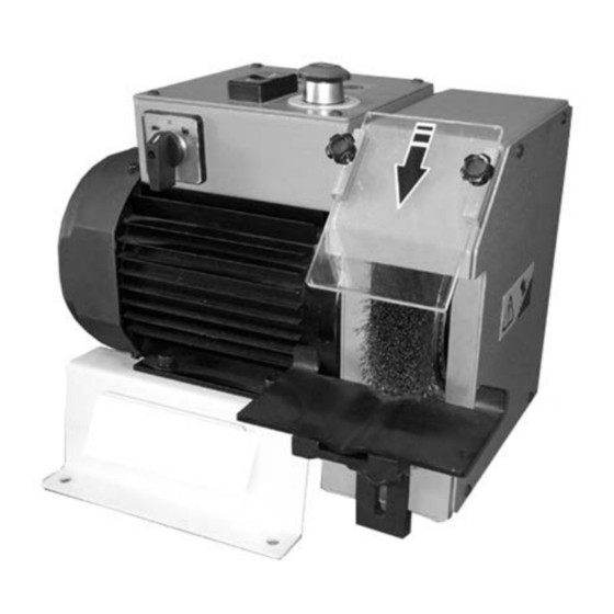
Shipping Contents Contents of the Carton Machine body (Fig 2) x 1 Fence A (Fig 3) x1 Screw C (Fig 3) x2 Material support down part D (Fig 3) x1 Material support UP part B (Fig 3) x1 Operating Instructions/Parts List (not shown) Fig 2 Fig 3... -
Page 8: Assembly
Assembly 1 Assemble the Material support down part D (Fig 3 ) as Fig 4 shown 2 Assemble the Material support Up part B (Fig 3 ) as Fig 4 shown 3 Assemble the Fence A (Fig 3 ) as Fig 4 shown Fig 4... -
Page 9: Controls And Indicators
Controls and Indicators Voltage and frequency of the machine Keep this manual in a good state and available at a close distance from the Name of the dealer from which the machine. machine was purchased. Description of the defect found, if any description of the type of operation Foreword carried out working hours per day. -
Page 10: Operations
Operations Control board (Fig. 6) E Start Motor Switch F Stop Motor Switch G Selector Motor Speed H E-Stop Fig 4 Execution of the deburring 1. Press the motor start switch E (Fig.4). 2. Select the motor speed G (Fig.4) 3. -
Page 11: Setting And Adjustments
Setting and Adjustment Support adjustment Adjust the support plate J ( Fig 6 ) to near the brush as close as possible Protect Cover adjustment Adjust the cover K (Fig 6) to against the chips . Fig 6 Brush's access protection To enter the brush , operate as follows: 1. - Page 12 Assembly of the brush For the assembly of brush operate by press it into the shaft Q (Fig 10 ) Assemble the motor shaft cover R (Fig 11) on . Use the screw S (Fig 11) to lock the cover Insert Hex-Wrench O (Fig.9) in the hole N (Fig 8) situated on the top of the motor spindle.
-
Page 13: Assembly Of The Blade
Maintenance OTHER RISKS In spite of the adopted security Maintenance must be carried out by directions, some other risks could qualified staff. The various operations remain. for the ordinary and extra ordinary 1. Electrical cabinet. The grid-feeding maintenance are indicated in the last voltage persists, so pay attention pages of this manual. -
Page 14: Troubleshooting
Troubleshooting Check: the cables, plug and socket. Also check Electrical power supply that the motor connections are in place. Check that the voltages are present both on the Transformer input and output. Otherwise replace. Check that the phases in it are present both on the input and output, that it is not jammed, that it Contactor closes when powered and that it is not causing... - Page 15 Assembly Drawing...
- Page 16 HU 200-4 DB PART LIST Description Description 1 Screws Handle M6*12 12 Key 2 Washer M6*16*1.5 13 Screws M4*10 Adjust seat-01 14 Screws Handle M5*10 Adjust seat-02 15 Acrylic Blinkers 5 Screws M5*10 16 Screws Handle M5*10 6 brush protect cover...
-
Page 17: Wiring Diagram And Parts
Assembly Parts Wiring Diagram and Parts Reference MODEL NO DESCRIPTION electromagnetic switch for motor 2KM1 S‐P09‐S/AC24V AC‐600V AZ1=1TH=20A CE speed control switch 2QM1 KEDU ZH‐HC‐4 25/16A 250V‐7.5HP 400V‐3HP CE light for motor start 2HL1 RENY R9PDNVO BA9S 2W MAX 24V MAX CE 2TC1 Transformer 400V/24V/10AV ITH10A‐Ui600V 2SB1 AP AUSPICIOUS 120V/6A/240V/3A CE Motor stop switch 2SB2 RENY R9C01VN AC15‐DC13 ITH10A‐Ui600V CE motor start switch 2SB3 RENY R9C10VN AC15‐DC13 ITH10A‐Ui600V CE ... - Page 19 No rights can be derived from this manual. All rights reserved. No part of this booklet may be reproduced in any form, by print, photoprint, microfilm or any other means without written permission from the publisher. © Huberts bv, Kennedylaan 14, Veghel, the Netherlands. Internet: www.huvema.nl...
Need help?
Do you have a question about the HU 200-4 DB and is the answer not in the manual?
Questions and answers