Advertisement
Quick Links
Advertisement

Related Manuals for Pakedge BR-WX-1


Summary of Contents for Pakedge BR-WX-1
- Page 1 BR-WX-1 WX-1 In-Ceiling/In-Wall Bracket INSTALLATION GUIDE...
-
Page 2: Package Contents
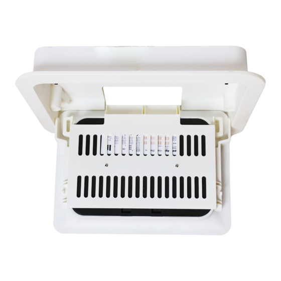
Package contents • BR-WX-1 In-Ceiling/In-Wall Bracket • Installation Guide • Installation screws BR-WX-1 The BR-WX-1 In-Ceiling/In-Wall Bracket is designed to mount the WX-1 directly into any wall or ceiling. Important: Read all instructions before attempting to install the bracket. - Page 3 BR-WX-1 mounting To install the bracket: 1 Press down on the AP bracket to release the AP bracket from the push latches on the in-ceiling bracket. AP bracket In-ceiling bracket...
- Page 4 2 Swing the AP bracket out from the in-ceiling bracket.
- Page 5 3 Slide both hinge arm locks towards the inside of the in-ceiling bracket to the open position. Hinge arm locks Hinge arm lock open position...
- Page 6 4 Press the hinge arms towards the center of the AP bracket to release the hinge pins from the hinge mounting holes on the in-ceiling bracket. While holding the hinge arms inward, slide the AP bracket out from the In-ceiling bracket. Hinge arm Hinge pin/hole...
- Page 7 5 Place the WX-1 into the AP bracket as shown, then secure it with the provided screws. Note: Install the AP bracket such that the LAN/Reset/DC/Kensington lock ports are aligned with their respective labels on the AP bracket.
- Page 8 6 Using the supplied template, cut a 10 1/4” x 7 5/8” rectangle at the desired mounting location for your WX-1. 7 Route an in-wall Ethernet cable through the opening of the in-ceiling bracket, then insert the in-ceiling bracket into the cutout.
- Page 9 8 Use a Phillips screwdriver to tighten the mounting ears. Note: Do not use excessive force when tightening the mounting ears, or the mounting ear threads may become stripped.
- Page 10 9 Plug an Ethernet cable into the WX-1, then press the hinge arms towards the center of the AP bracket. Hinge mounting hole Hinge pin Hinge mounting hole Hinge pin 10 While holding the hinge arms inward, insert the AP bracket/WX-1 assembly into the in-ceiling bracket.
- Page 11 12 Slide both hinge arm locks away from the in-ceiling bracket to the closed position. Hinge arm lock closed position...
- Page 12 13 Swing the AP bracket/WX-1 assembly into the in-ceiling bracket until the AP bracket is secured to the two push latches. An audible click will be heard when the AP bracket is secured to the push latch. Note: Make sure the hinge arm locks are in their closed position before swinging the AP bracket/WX-1 assembly into the in-ceiling bracket.
- Page 13 2 Drill 1/16” pilot holes at the marked locations, then secure the pre-construction bracket to ceiling studs using the provided hardware. (Note: The Pakedge logo should face out.) 3 Install sheetrock over the pre-construction bracket. Make note of where the cutout on the pre-construction bracket is when installing the drywall.
- Page 14 Accessing WX-1 LAN/Reset 1 Press the center of the WX-1 in towards the ceiling/wall until the AP bracket has been released from the two push latches. An audible click can be heard when the push latches are released.
- Page 15 2 After the AP bracket has been released from the push latches, swing the WX-1 out from the in-ceiling bracket.
- Page 16 3 Slide the hinge arm locks towards the inside of the in-ceiling bracket to the open position. Hinge arm lock open position...
- Page 17 4 Press the hinge arms towards the center of the AP bracket to release the hinge pins from the hinge mounting holes on the in-ceiling bracket. 5 While holding the hinge arms inward, slide the AP bracket out from the in-ceiling bracket to access the LAN port and Reset button.
-
Page 18: Technical Support
(650) 385-8703 For non-technical inquires: customerservice@pakedge.com (650) 385-8701 For regulatory information: www.pakedge.com/regulatory 11734 S. Election Road Draper, UT 84020 Main: (650) 385-8700 Fax: (650) 685-5520 www.pakedge.com sales@pakedge.com DOC-00250-B 2016-11-17 MS ©2016 Pakedge Device & Software Inc. All rights reserved.
Need help?
Do you have a question about the BR-WX-1 and is the answer not in the manual?
Questions and answers