Table of Contents
Advertisement
Quick Links
Advertisement
Table of Contents

Summary of Contents for Motortech NOX
- Page 1 Sensor Installation Instruction P/N 01.50.027-EN | Rev. 09/2020...
- Page 2 MOTORTECH products and the MOTORTECH logo are registered and/or common law trademarks of the MOTORTECH GmbH. All further trademarks and logos displayed or used in this publication are the property of the respective entitled person and are used for reference purposes only.
-
Page 3: Table Of Contents
Table of Contents 1 General Information ..................... 5 1.1 What Is the Purpose of this Installation Instruction? ..........5 1.2 Who Is this Installation Instruction Targeted to? ............5 1.3 What Symbols Are Used in the Installation Instruction? ..........5 ... - Page 4 Table of Contents 6.2 Returning Equipment for Repair / Inspection ............25 6.3 Instructions for Packaging the Equipment .............. 25 7 Maintenance ......................26 7.1 Cleaning the NO Sensor ..................26 7.2 Spare Parts and Accessories ................. 26 Rev.
-
Page 5: General Information
1 General Information Prior to use, read this installation instruction carefully and familiarize yourself with the product. Installation and start-up should not be carried out before reading and understanding this docu- ment. Keep this installation instruction readily available so that you can reference it as needed. 1.1 What Is the Purpose of this Installation Instruction? This installation instruction serves as an aid for the installation of the product and supports the technical staff with all maintenance tasks to be performed. -
Page 6: Which Abbreviations/Acronyms Are Used In The Installation Instruction
1 General Information Danger This symbol indicates warnings for danger to life, especially due to high voltage. Read these warning notices carefully and take the mentioned precautionary measures. 1.4 Which Abbreviations/Acronyms Are Used in the Installation Instruction? The following abbreviations/acronyms are used in the installation instruction. Abb. -
Page 7: Safety Instructions
2 Safety Instructions 2.1 General Safety Instructions MOTORTECH equipment is manufactured as state of the art and therefore safe and reliable to operate. Nevertheless the equipment can cause risks or damage can occur, if the following instructions are not complied with: –... -
Page 8: Electrostatic Discharge Hazards
2 Safety Instructions 2.2 Electrostatic Discharge Hazards Electronic equipment is sensitive to static electricity. To protect these components from damage caused by static electricity, special precautions must be taken to minimize or prevent electro- static discharge. Observe these safety precautions while you work with the equipment or in its vicinity. –... -
Page 9: Proper Transport
(see section Mounting on page 20). 2.5 Proper Disposal After the expiration of its service life, MOTORTECH equipment can be disposed of with other commercial waste, or it may be returned to MOTORTECH. We will ensure its environmentally friendly disposal. -
Page 10: Intended Use
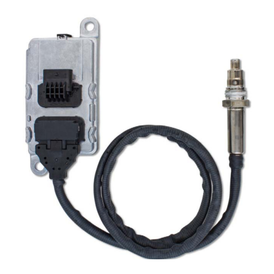
3 Intended Use 3.1 Functional Description The NO sensor measures the nitrogen oxide and oxygen concentration in the exhaust gas of stationary gas engines in industrial environments and transmits the measured values via the CAN bus to a master control. 3.2 Applications The NO sensor is designed for use on stationary gas engines in industrial environments in a... -
Page 11: Product Description
4 Product Description 4.1 Technical Data 4.1.1 Certifications The NO sensor is certified as follows: EMC Directive – EN 61326-2-3 – Electrical equipment for measurement, control and laboratory use - EMC requirements - Part 2-3: Particular requirements - Test configurations, operational condi- tions and performance criteria for transducers with integrated or remote signal conditioning –... -
Page 12: Mechanical Data
See section Overview Drawings on page 16 IP protection rating IP 6K9K with mating plug connected to evaluation unit and sensing element mounted in suitable welding boss from MOTORTECH Climatic environmental conditions Operating temperature evaluation unit: –40 °C to +115 °C (–40 °F to +239 °F) Operating temperature hexagon nut: –40 °C to +620 °C (–40 °F to +1,148 °F) -
Page 13: Product Identification - Labeling On The Device
4 Product Description 4.1.3 Product Identification – Labeling on the Device The part number (P/N) of the NO sensor can be found on the upper label on the bottom side of the evaluation unit. The date of manufacture and the serial number of the NO sensor can be read out via the two- dimensional matrix code (Data Matrix) on the connector of the evaluation unit. -
Page 14: Electrical Data
4 Product Description 4.1.4 Electrical Data The NO sensor has the following electrical characteristics: Feature Value Power supply 24 V DC (16 V DC to 36 V DC) Maximum power consumption 20 W Required current Max. 1.5 A , 6.2 A peak Connector evaluation unit 5-pole, connector... -
Page 15: Interfaces
4 Product Description Table 1: Measuring accuracy nitric oxide (NO) Measurement Measuring accuracy at evaluation unit operating temperature –40 °C to +105 °C +106 °C to +115 °C (–40 °F to +221 °F) (+222.8 °F to +239 °F) NO ≤ 100 ppm ±... -
Page 16: Overview Drawings
4 Product Description 4.1.6 Overview Drawings Dimensions Rev. 09/2020... -
Page 17: Mounting Instruction
5 Mounting Instruction Replacement of NO sensor in EasyNO system If you want to replace an identical NO sensor from MOTORTECH in the exhaust pipe, read the section Replacement of NO Sensor in the EasyNO operating manual. 5.1 Preparation Make sure that your application meets the following requirements. -
Page 18: Mounting Position Of Sensing Element
The possible tilt angles depend on the course of the exhaust pipe. Mounting in a vertical exhaust pipe is not recom- mended by MOTORTECH. Horizontal exhaust pipe tilt angles... -
Page 19: Unpacking
Locking screw for welding boss from MOTORTECH – Suitable harness from MOTORTECH for connecting the NO sensor to the master control If you have any questions about the needed material, contact your MOTORTECH contact person (see Customer Service Information on page 25). Rev. 09/2020... -
Page 20: Mounting
(material number 1.4301) from MOTORTECH and connected to the master control via a suitable harness from MOTORTECH. For welding in the welding boss, the locking screw of the welding boss can be used as welding aid. - Page 21 5 Mounting Instruction Proceed as follows: At the selected mounting position in the exhaust pipe, drill a hole with a diameter of 27 mm ± 1 mm (1.07" ± 0.04") into the exhaust pipe. 2. Screw the locking screw into the welding boss and weld the stainless steel welding boss (material number 1.4301) into this hole with a suitable welding filler.
-
Page 22: Setting Can Identifier
0x18F00F52 = Parameter group number 61455, source address 82: Pin 5 is open. 5.6 Setting up Master Control If you use a master control from MOTORTECH that is prepared for use with the NO sensor (e.g. EasyNO ), you must in certain cases configure the control before you can carry out measure- ments with the NO sensor. -
Page 23: Dismounting
If mechanical shock to the sensing element occurs (e.g. drop on the floor), the NO sensor must not be used under any circumstances and must be disposed of. In cases of doubt, contact your MOTORTECH con- tact person (see Customer Service Information on page 25). Operational safety! The sensing element may be mounted and dismounted a maximum of two times. - Page 24 5 Mounting Instruction 2. Dismount the evaluation unit from the mounting plate. Risk of destruction! To avoid destroying the NO sensor, do not hit with a hammer when dis- mounting. In case the thread of the sensing element is stuck, use only oils without silicon or magnesium for loosening.
-
Page 25: Errors
6.2 Returning Equipment for Repair / Inspection To return the device for repair and inspection, obtain a return form from your MOTORTECH con- tact person (see Customer Service Information on page 25). After you have completely filled out the return form and returned it to MOTORTECH, MOTORTECH will send you back the return form and a delivery note with RMA number specified. - Page 26 7.2 Spare Parts and Accessories For spare parts and accessories, please refer to our current Product Guide, which is available for you to download on the internet at www.motortech.de. Rev. 09/2020...
- Page 27 Rev. 09/2020...
Need help?
Do you have a question about the NOX and is the answer not in the manual?
Questions and answers