Table of Contents
Advertisement
INSTRUCTIONS FOR USE – rev. 2017-04
AG-tronik M1 AND REGULATOR PR-9
ELEKTRONSKA
REGULACIJA
ELECTRONIC REGULATION
Ag-tronik M1
INSTRUCTIONS FOR USE
rev.2017-04
AGROMEHANIKA reserves the right to change the design or modify the product without any
obligation of informing the customer before and after each change.
1
Advertisement
Table of Contents

Summary of Contents for Agromehanika Ag-tronik M1
- Page 1 INSTRUCTIONS FOR USE – rev. 2017-04 AG-tronik M1 AND REGULATOR PR-9 ELEKTRONSKA REGULACIJA ELECTRONIC REGULATION Ag-tronik M1 INSTRUCTIONS FOR USE rev.2017-04 AGROMEHANIKA reserves the right to change the design or modify the product without any obligation of informing the customer before and after each change.
- Page 2 INSTRUCTIONS FOR USE – rev. 2017-04 AG-tronik M1 AND REGULATOR PR-9...
-
Page 3: Table Of Contents
INSTRUCTIONS FOR USE – rev. 2017-04 AG-tronik M1 AND REGULATOR PR-9 INTRODUCTION ......................5 AG-tronik DESCRIPTION ....................5 FUNCTION DIAGRAM OF THE SYSTEM ..............7 AG-tronik CONNECTION ....................8 DESCRIPTION OF THE DISPLAY ................10 AG-tronik KEYS DESCRIPTION ................... 12 OPERATION DESCRIPTION –... - Page 4 INSTRUCTIONS FOR USE – rev. 2017-04 AG-tronik M1 AND REGULATOR PR-9 Excel printout: ........................54 Deleting files from SD card: .................... 56 GPS OUTPUT ....................... 57 12.1. GPS output 12 V ......................57 12.2. GPS serial communication ..................57 OFF protocol: ........................58 MANUAL protocol: ......................
-
Page 5: Introduction
INSTRUCTIONS FOR USE – rev. 2017-04 AG-tronik M1 AND REGULATOR PR-9 1. INTRODUCTION We thank you for purchasing automatic regulation. Instructions will help you to get to know and operate AG-tronik. Read the manual thoroughly before use, because properly adjusted AG-tronik achieves set value of liter per hectare much more precisely. - Page 6 INSTRUCTIONS FOR USE – rev. 2017-04 AG-tronik M1 AND REGULATOR PR-9 Figure 5 DISPLAY Key ON/OFF Key AUTOMATIC Key PRESSURE INCREASE (manual control) Key PRESSURE DECREASE (manual control) Key PROGRAM Key FUNCTION Key MAIN VALVE ON/OFF Keys SECTIONS ON/OFF with two-colour LED diodes for spraying display (red –...
-
Page 7: Function Diagram Of The System
INSTRUCTIONS FOR USE – rev. 2017-04 AG-tronik M1 AND REGULATOR PR-9 3. FUNCTION DIAGRAM OF THE SYSTEM Figure 6 1. AG-tronik M1 2. Distributing solenoid valves 3. Speed sensor 4. Flow sensor 5. Pressure regulator 6. Power supply 12 V AG-tronik receives information, required for calculation of actual liter per hectare from: ... -
Page 8: Ag-Tronik Connection
4. AG-tronik CONNECTION If you are not skilled in such work, we recommend that the electronic regulation is installed by an authorized service of Agromehanika. If you have decided to install it yourself, a brief installation description is given further on. - Page 9 INSTRUCTIONS FOR USE – rev. 2017-04 AG-tronik M1 AND REGULATOR PR-9 Signal for speed measurement can be taken from the tractor to the extent that the tractor has speed measuring and appropriate output via a connector. 7-pin plug connection cable code: 018.60.530, in this case connect it to a connector which is mounted in tractor, 4-pin plug,...
-
Page 10: Description Of The Display
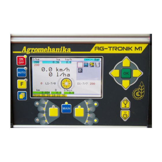
When you press the key the display turns on. At first, for a few seconds, there is sign AG-tronik M1 on display and below is current version and date of software. Figure 10 The basic display contains the following information:... - Page 11 INSTRUCTIONS FOR USE – rev. 2017-04 AG-tronik M1 AND REGULATOR PR-9 Current liter per hectare in l/ha. Upon start-up or when we do not spray, value 0 is displayed. This is the largest display, because it is the most important one.
-
Page 12: Ag-Tronik Keys Description
INSTRUCTIONS FOR USE – rev. 2017-04 AG-tronik M1 AND REGULATOR PR-9 6. AG-tronik KEYS DESCRIPTION Keys for turning on, AUTO, MAIN and sections have a LED next to the key, which lights up or blinks, when the key is on. LEDs are red, except the key for turning on, which has a green LED. -
Page 13: Operation Description - Manual Control
INSTRUCTIONS FOR USE – rev. 2017-04 AG-tronik M1 AND REGULATOR PR-9 7. OPERATION DESCRIPTION – MANUAL CONTROL Spraying in manual control is done with settings, which are input manually. This enables to increase or decrease pressure during work and therefore change liter per hectare. Spraying is therefore done without a computer or without automatic regulation. -
Page 14: Operation Description - Automatic Control
INSTRUCTIONS FOR USE – rev. 2017-04 AG-tronik M1 AND REGULATOR PR-9 8. OPERATION DESCRIPTION – AUTOMATIC CONTROL In automatic control, set hectare dosage is controlled by AG-tronik. Of course, all of the following conditions must be met: correct choice of spraying parameters, such as correct choice of spraying speed, correct choice of nozzles... -
Page 15: Spraying
INSTRUCTIONS FOR USE – rev. 2017-04 AG-tronik M1 AND REGULATOR PR-9 valve is closed, mixing through mixing nozzle does not occur (unless the mixing is done through the mixing pump). Ensure appropriate pressure of 2-10 bar. If required, reset daily counters (ha, km, l). -
Page 16: Programming
INSTRUCTIONS FOR USE – rev. 2017-04 AG-tronik M1 AND REGULATOR PR-9 9. PROGRAMMING To enter program "PROGRAMMING", use quick menus. Menus are located in top right part of display. Red frame marks icon of individual chapter. QUICK MENUS "PROGRAMMING" Figure 12... -
Page 17: Hectare Consumption
INSTRUCTIONS FOR USE – rev. 2017-04 AG-tronik M1 AND REGULATOR PR-9 HECTARE CONSUMPTION TANK FILLING DELETING DAILY COUNTERS OF SPRAY CONSUMPTION (l), SURFACE AREA (ha) and PATH (km) GPS DEVICE TYPE SETTING FLOW CONSTANT SPEED CONSTANT WORKING WIDTH NOZZLE SETTINGS... -
Page 18: Filling Of Tank
INSTRUCTIONS FOR USE – rev. 2017-04 AG-tronik M1 AND REGULATOR PR-9 Figure 17 If you do not want to change the value of hectare consumption, press button to return to previous window. If you want to change the value, press button... - Page 19 INSTRUCTIONS FOR USE – rev. 2017-04 AG-tronik M1 AND REGULATOR PR-9 To enter window "TANK FILLING", select icon and confirm it with confirmation button . The display shows: Figure 19 In the line “VOLUME OF CHEMICAL IN TANK” AG-tronik offers the last set value and in...
-
Page 20: Deleting Daily Counters Of Spray Consumption (L), Surface Area (Ha) And Path (Km)
INSTRUCTIONS FOR USE – rev. 2017-04 AG-tronik M1 AND REGULATOR PR-9 9.3. Deleting daily counters of spray consumption (l), surface area (ha) and path (km) To delete daily counters, select icon and confirm it with confirmation button The display shows:... -
Page 21: Flow Constant
INSTRUCTIONS FOR USE – rev. 2017-04 AG-tronik M1 AND REGULATOR PR-9 If you want to change the type of GPS device, move selection window to type, press button , and GPS device starts flashing. Use button to move in the drop-down menu and select corresponding type. -
Page 22: New Constant
INSTRUCTIONS FOR USE – rev. 2017-04 AG-tronik M1 AND REGULATOR PR-9 Figure 23 This window offers three options: new constant known flow correction; move the symbol √ and choose the way of changing flow constant. With key Press key to open a separate window. -
Page 23: Known Flow
INSTRUCTIONS FOR USE – rev. 2017-04 AG-tronik M1 AND REGULATOR PR-9 Known flow: Is used, if the constant is unknown or if flow through flow sensor changed significantly (replace nozzle inserts with greater or smaller flow). In this case, measure flow capacity of nozzles at defined pressure. -
Page 24: Correction
INSTRUCTIONS FOR USE – rev. 2017-04 AG-tronik M1 AND REGULATOR PR-9 Press key to move the frame to the value of parameter flow/nozzle. Press key and the value start to blink. Set new value with keys . Press key again and the display changes the value of common flow (in our case the value is set to 17,60 1) and in the lower left corner –MEASUREMENT- is displayed. -
Page 25: Speed Constant
INSTRUCTIONS FOR USE – rev. 2017-04 AG-tronik M1 AND REGULATOR PR-9 Select line CORRECTION and press key to open the following window: Figure 30 Figure 31 Following quantities are displayed: current constant imp/l (711) measured quantity (393) actual quantity (393) Actual quantity is selected and when you press key , it starts t blink. -
Page 26: New Constant
INSTRUCTIONS FOR USE – rev. 2017-04 AG-tronik M1 AND REGULATOR PR-9 To enter window "SPEED CONSTANT", select icon and use confirmation button to confirm it. The display shows: Figure 34 Window offers three options: o new constant o parameters r, N... -
Page 27: Parameters R, N
INSTRUCTIONS FOR USE – rev. 2017-04 AG-tronik M1 AND REGULATOR PR-9 Speed constant was calculated with the equation above. This is input in AG-tronik. In speed constant menu choose line NEW CONSTANT and press key to open the following window:... -
Page 28: Distance
INSTRUCTIONS FOR USE – rev. 2017-04 AG-tronik M1 AND REGULATOR PR-9 New value is displayed. If you want to change value of marks N, press button selection frame selects field of mark N. Press button and value starts flashing. Use... -
Page 29: Speed
INSTRUCTIONS FOR USE – rev. 2017-04 AG-tronik M1 AND REGULATOR PR-9 is 861 imp. Use buttons to set previously measured value. In our case, the value is 250 m. Use button to confirm entry. New value of imp/km is displayed. In our case, value of imp/km is 3444. -
Page 30: Row Spacing
INSTRUCTIONS FOR USE – rev. 2017-04 AG-tronik M1 AND REGULATOR PR-9 Actual km/h We see that speed on AG-tronik is not accurate since data from GPS or tractor speedometer are showing different speed. If you discover that accurate speed is 10,1 km/h, you can set new value with buttons . -
Page 31: Nozzle Settings
INSTRUCTIONS FOR USE – rev. 2017-04 AG-tronik M1 AND REGULATOR PR-9 Figure 45 In field D enter the spacing in plantation to be treated. When you press button value D starts to flash. Using the buttons set new value. With button confirm the entry. -
Page 32: Setting Nozzle Segment
INSTRUCTIONS FOR USE – rev. 2017-04 AG-tronik M1 AND REGULATOR PR-9 When using the same nozzle height, and if the left side is symmetrical to right side by number of nozzles, then entered data do not have such importance, as the right hectare dosage is taken care by flowmeter in other situations it is necessary to enter the correct information. - Page 33 INSTRUCTIONS FOR USE – rev. 2017-04 AG-tronik M1 AND REGULATOR PR-9 Figure 48 On screen there are icons L-2 and D-2. In basic menu you can see split segment and additional text: Figure 50 Figure 51 Figure 50 displays sprayer with one segment and figure 51 displays sprayer with double segment.
-
Page 34: Nozzle Settings
INSTRUCTIONS FOR USE – rev. 2017-04 AG-tronik M1 AND REGULATOR PR-9 Figure 52 displays X in bottom line, which indicates that nozzle is closed. In this case there is text D1-7/6 in basic menu. There are 7 nozzles mounted on sprayer and 6 of them are open. -
Page 35: The Use Of Different Nozzles On One Sprayer Segment
INSTRUCTIONS FOR USE – rev. 2017-04 AG-tronik M1 AND REGULATOR PR-9 Figure 54 The movement in columns and rows is enable with buttons With button select and confirm value, button is intended to exit or switch to higher level. The column "Bar" and "ISO" are values of flow at a given rate for selected nozzle (yellow nozzle has a flow of 1,46 l/min. -
Page 36: General Settings
INSTRUCTIONS FOR USE – rev. 2017-04 AG-tronik M1 AND REGULATOR PR-9 9.9 General settings To enter window "GENERAL SETTINGS", select icon and use confirmation button to confirm it. The display shows: Figure 56 Window includes signs for: year ... -
Page 37: Minimum Spraying Speed
INSTRUCTIONS FOR USE – rev. 2017-04 AG-tronik M1 AND REGULATOR PR-9 CRO, SRB – Serbo-Croatian H – Hungarian CZ – Czech BG – Bulgarian RO – Russian ITA – Italian ESP – Spanish ... - Page 38 INSTRUCTIONS FOR USE – rev. 2017-04 AG-tronik M1 AND REGULATOR PR-9 Press or hold button to change speed, and change pressure with buttons . Pressure can be changed only in manual protocol. Automatic protocol is possible, when flow is greater than 8 l/min. Simulation enables simulation of spraying, opening valves,...
-
Page 39: Analyses
INSTRUCTIONS FOR USE – rev. 2017-04 AG-tronik M1 AND REGULATOR PR-9 ANALYSES To enter program "ANALYSES", use quick menus. Menus are located in top right part of display. Red frame marks icon of individual chapter. QUICK MENUS "ANALYSES" Figure 58... -
Page 40: Tank
INSTRUCTIONS FOR USE – rev. 2017-04 AG-tronik M1 AND REGULATOR PR-9 Move to desired icon left and up with button , right and down with button . Use confirmation button to select correct chapter. Let's go through individual chapters: 10.1. Tank... -
Page 41: Flow Analysis
INSTRUCTIONS FOR USE – rev. 2017-04 AG-tronik M1 AND REGULATOR PR-9 confirmed with button . In case this is all done, you can switch back to main menu with button 10.2. Flow analysis Select icon and use confirmation button to confirm it. The display shows current... - Page 42 INSTRUCTIONS FOR USE – rev. 2017-04 AG-tronik M1 AND REGULATOR PR-9 Lot name Nozzle size Nozzle type Culture Chemical 1 Chemical 2 Chemical 3 Chemical 4 AG-tronik collects and calculates all other parameters. Let us take a look at other parameters, which are a part of analysis.
-
Page 43: New Work
INSTRUCTIONS FOR USE – rev. 2017-04 AG-tronik M1 AND REGULATOR PR-9 Figure 62 Press button to confirm window START/CONTINUE. New window opens: Figure 63 If you decide not to monitor spraying with analysis, select and confirm "X". Window returns to previous window. - Page 44 INSTRUCTIONS FOR USE – rev. 2017-04 AG-tronik M1 AND REGULATOR PR-9 name. Use button to move to next line. Lines, where input or confirmation is required, are in the following order: Lot name Culture Chemical 1 Chemical 2 ...
- Page 45 INSTRUCTIONS FOR USE – rev. 2017-04 AG-tronik M1 AND REGULATOR PR-9 . If you have made a mistake, you can delete a character or series of characters with symbol “Del”. Once you have finished inputting culture, confirm it with symbol “Ent”.
-
Page 46: Continue Work
INSTRUCTIONS FOR USE – rev. 2017-04 AG-tronik M1 AND REGULATOR PR-9 Press confirmation button to activate analysis. Briefly, ANALYSIS IN PROGRESS is displayed under the bottom line. Continue work: If you have changed nozzle and/or type of chemical and/or chosen another nozzle type or just continued work on the same lot after a few days, without conducting analysis on other lots, all data does not need to be input in AG-tronik;... - Page 47 INSTRUCTIONS FOR USE – rev. 2017-04 AG-tronik M1 AND REGULATOR PR-9 Figure 73 If you have chosen not to cancel the analysis, simply choose NO and return to the previous window. If you select " " and confirm with confirmation button...
-
Page 48: Rename
INSTRUCTIONS FOR USE – rev. 2017-04 AG-tronik M1 AND REGULATOR PR-9 Rename: This part of program is intended for renaming already input lots. If you wish to rename a lot, move selection frame to line RENAME. Press confirmation button to open new... -
Page 49: Deleting
INSTRUCTIONS FOR USE – rev. 2017-04 AG-tronik M1 AND REGULATOR PR-9 Deleting: This part of program is intended for deleting existing lots. If you wish to delete a lot, move selection frame to line DELETE. Press button to delete selected name. Press button to return to basic menu "WORK". - Page 50 INSTRUCTIONS FOR USE – rev. 2017-04 AG-tronik M1 AND REGULATOR PR-9...
-
Page 51: General
INSTRUCTIONS FOR USE – rev. 2017-04 AG-tronik M1 AND REGULATOR PR-9 Figure 79-90 Data, written in analysis, are the following: ANALYSIS: Lot name: CULTURE: CHEMICAL 1: CHEMICAL 2: CHEMICAL 3: CHEMICAL 4: START: STOP: XXXXXXXX: AUTOMATIC: Time of work: Travelled distance (km):... - Page 52 INSTRUCTIONS FOR USE – rev. 2017-04 AG-tronik M1 AND REGULATOR PR-9 Figure 91 Figure 92 If you wish to restore AG-tronik to factory settings, hold button for approximately 4 seconds, until message "RESTART FACTORY SETTINGS?" is displayed. If you do not want to restore it to factory settings, select and confirm "X" and window returns to previous window.
-
Page 53: Printouts
INSTRUCTIONS FOR USE – rev. 2017-04 AG-tronik M1 AND REGULATOR PR-9 PRINTOUTS 11.1. Inserting SD card AG-tronik writes analyses to SD memory card, which you received upon purchase of automatic regulation. Writing to SD memory card is described in detail in the chapter 10 "ANALYSES", subchapter 10.3 "WORK". -
Page 54: Excel Printout
INSTRUCTIONS FOR USE – rev. 2017-04 AG-tronik M1 AND REGULATOR PR-9 BEGIN marks the start/continue of specific ANALYSIS, and END marks cancel/end of ANALYSIS. Each cancel makes a new start and end of specific ANALYSIS. Printouts are prepared so that they are all gathered under one lot. - Page 55 INSTRUCTIONS FOR USE – rev. 2017-04 AG-tronik M1 AND REGULATOR PR-9 When transferring, pay attention to transfer mode. First, window on figure 98 opens, where you choose "Fixed width" of field; then continue to the next window (figure 99). In this window, you define field widths and can be skipped (figure 99).
-
Page 56: Deleting Files From Sd Card
INSTRUCTIONS FOR USE – rev. 2017-04 AG-tronik M1 AND REGULATOR PR-9 Deleting files from SD card: If the number of files on the card is too great or the card is full, old files or files that are no longer useful must be deleted. Insert SD card in the reader and connect it to personal computer. -
Page 57: Gps Output
GPS device, with which you can control the sprinkler precisely to section. Before purchasing GPS device, consult with authorized dealer for Agromehanika, if the GPS device is compatible with AG-tronik. 12.1. GPS output 12 V If GPS navigation device enables connection of external signal, which control operation of "MAIN"... -
Page 58: Off Protocol
INSTRUCTIONS FOR USE – rev. 2017-04 AG-tronik M1 AND REGULATOR PR-9 OFF protocol: If you do not wish to use GPS device in connection with AG-tronik, select OFF protocol in AG-tronik. Use this protocol also if you have a GPS device, which is not compatible with AG- tronik. - Page 59 INSTRUCTIONS FOR USE – rev. 2017-04 AG-tronik M1 AND REGULATOR PR-9 speed open status of section valves open status of main valve sprayed (ha) hectare dose path This data is important for correct regulation and operation of sprinkler. E.g. AG-tronik receives speed from GPS devices, as it is much more accurate, because it does not include sliding, sinking, speed in turns..., data on hectare dose, which is important for analysis of...
- Page 60 INSTRUCTIONS FOR USE – rev. 2017-04 AG-tronik M1 AND REGULATOR PR-9 PRESSURE REGULATOR PR-9EC...
-
Page 61: Regulator Pr-9Ec Description
INSTRUCTIONS FOR USE – rev. 2017-04 AG-tronik M1 AND REGULATOR PR-9 REGULATOR PR-9EC DESCRIPTION Flow regulator PR-9EC is intended for electronic or remote regulation of working pressure on all types of sprayers, with which working pressure from 0 to maximum 20 bar is used. -
Page 62: Main Components Of Pressure Regulator Pr-9
INSTRUCTIONS FOR USE – rev. 2017-04 AG-tronik M1 AND REGULATOR PR-9 Components: Pressure regulator PR-9, figure 104 AG-tronik M1, figure 105 Connecting cable from regulator to Ag-tronik, figure 106 Extension cable for speedometer, figure 107 Speedometer, figure 108 13.2. -
Page 63: Description Of Main Component Parts Of The Regulator
INSTRUCTIONS FOR USE – rev. 2017-04 AG-tronik M1 AND REGULATOR PR-9 DESCRIPTION OF MAIN COMPONENT PARTS OF THE REGULATOR 15.1. Pressure regulation With electromotor valve you can regulate pressure of spraying. Controlling of regulation valve is in AUTO mode and with help from AG-tronik, or buttons on AG-tronik (chapter 2 DESCRIPTION OF AG-tronik). -
Page 64: Manual Regulation Valve
INSTRUCTIONS FOR USE – rev. 2017-04 AG-tronik M1 AND REGULATOR PR-9 15.3. Manual regulation valve Regulating nut Manual regulation valve is for manual settings of maximum pressure in system, that is in sprayer. In fact this is safety valve, which can be adjusted with the nut. The pressure is increasing by turning the nut in clock wise direction and vice versa. -
Page 65: Flow Sensor
INSTRUCTIONS FOR USE – rev. 2017-04 AG-tronik M1 AND REGULATOR PR-9 Distribution valves EC, with the help of built-in solenoids, open and close flow to individual parts of spraying segments. Opening and closing of valves is performed exclusively with buttons on AG-tronik (chapter 2, DESCRIPTION OF AG-tronik). -
Page 66: Connector
INSTRUCTIONS FOR USE – rev. 2017-04 AG-tronik M1 AND REGULATOR PR-9 If there are greater deviations of flow constant from planned value, the cause can be incorrect operation of flow sensor. In this case, thoroughly clean the sensor, especially in the sensor turbine area. -
Page 67: Speed Sensor
INSTRUCTIONS FOR USE – rev. 2017-04 AG-tronik M1 AND REGULATOR PR-9 15.9. Speed sensor Speed measurement, if performed through induction no-contact sensor. On driven sprinklers, the sensor is installed on rear right wheel axle (figure 120). On carried sprinklers, it is installed on tractor housing and measures passages of wheel nuts. - Page 68 If the tractor has an output signal for measuring speed, signal from the tractor is used instead of no-contact sensor. In this case, the tractor connector is connected to AG-tronik M1. Required connection cable code: 018.60.530. Speed constant for input in AG-tronik is 1024.
-
Page 69: Wiring Diagram
INSTRUCTIONS FOR USE – rev. 2017-04 AG-tronik M1 AND REGULATOR PR-9 WIRING DIAGRAM Wiring diagram on figure is a classic wiring diagram for spraying devices. Pressure regulator consists of central valve, distribution valves, flow meter, filter... Flow travels from tank through suction collector and pump to pressure regulator. Central MAIN valve is basically an option valve, which directs flow to nozzles and other devices (filling container, mixing...) or back in the tank. -
Page 70: Maintenance
INSTRUCTIONS FOR USE – rev. 2017-04 AG-tronik M1 AND REGULATOR PR-9 MAINTENANCE 1. After each spraying, the regulator must be thoroughly washed with clean water, because only this helps to keep the regulator in good condition, operation errors are fewer, which reduces the costs of service.
Need help?
Do you have a question about the Ag-tronik M1 and is the answer not in the manual?
Questions and answers