Advertisement
Table of Contents
- 1 Table of Contents
- 2 Overview
- 3 Tower Installation
- 4 Piping to Tower
- 5 Mechanical Equipment Installation
- 6 Motor Electrical Connections
- 7 Starting and Operating Instructions
- 8 Freezing Weather Operation
- 9 Maintenance Instructions
- 10 Blowdown
- 11 Cooling Tower Inspection and Maintenance
- 12 Seasonal Shutdown Instructions
- 13 Troubleshooting
- 14 Wiring Diagrams
- Download this manual
Advertisement
Table of Contents

Subscribe to Our Youtube Channel
Related Manuals for Marley Aquatower


Summary of Contents for Marley Aquatower
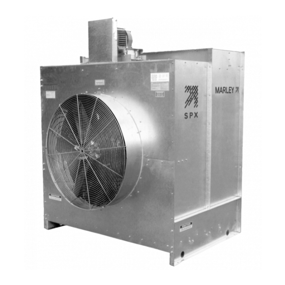
- Page 1 ® Aquatower cooling tower I N S TA L L AT I O N - O P E R AT I O N - M A I N T E N A N C E...
-
Page 2: Table Of Contents
contents This Manual contains vital information for the proper installation and operation of your cooling tower. Carefully read the manual before installation or operation of the tower and follow all instructions. Save this manual for future reference. Overview ........................3 Tower Installation......................5 Piping to Tower ......................5 Mechanical Equipment Installation .................6 Motor Electrical Connections ...................9... -
Page 3: Overview
If you have questions about the operation and/or maintenance of this cooling tower, and you don’t find the answers in this manual, please contact your Marley sales representative. When writing for information, or when ordering parts, please include the serial number shown on the cooling tower nameplate. - Page 4 installation Tower Location The cooling tower must be located at such distance and direction Warning to avoid the possibility of contaminated tower discharge air being drawn into building fresh air intake ducts. The purchaser should ob- tain the services of a Licensed Professional Engineer or Registered Architect to certify that the location of the tower is in compliance with applicable air pollution, fire, and clean air codes.
-
Page 5: Tower Installation
installation Tower Installation Install tower in a level position on a stable foundation. Anchor tower to the foundation through holes at base of tower, using four M10 diameter bolts (not supplied). Remove strapping and brackets from the louver face on models 494—496 and reinstall the bolts to the cold water basin. -
Page 6: Mechanical Equipment Installation
Motor, Sheave, and V-Belt Installation 1. Check the motor nameplate to be sure its voltage, phase and frequency ratings are the same as the power supply. ➠ BELT GUARD FOR STEEL AQUATOWER SHOWN Motor Frame Fastener Size 1/4" TAP SCREW 56–143T–145T ⁄... - Page 7 installation 2. Make sure the fan is tightly secured to the bearing housing shaft and that it rotates freely. Make sure the bearing housing is secured to its support. 3. Attach motor to motor base with four bolts, flat washers, lock washers and nuts provided, see Figure 3.
- Page 8 9. Install fan cylinder splice plate (steel tower) and fan guard. 10. Check bearing housing oil cup level. Fill to the proper level with SAE 30 (ISO 100) weight oil. BELT GUARD FOR FIBERGLASS AQUATOWER SHOWN 3/8" x 1 1/2" BOLT 3/8" WASHERS USE 3/8" WASHERS TO SHIM AS REQUIRED 3/8"...
-
Page 9: Motor Electrical Connections
Motor Electrical Connections If Aquatower is equipped with Marley Control System, refer to Con- Note trol System Manual for wiring instructions. Internal space heaters may be present, depending upon the motor manufac- turer. For space heater operation and wiring refer to Marley “Fan Motor”... -
Page 10: Starting And Operating Instructions
operation Starting and Operating Instructions Microorganisms including Legionella bacteria can exist in premise Warning plumbing including cooling towers. The development of an effective water management plan (WMP) and implementation of maintenance procedures are essential to prevent the presence, dissemination and amplification of Legionella bacteria and other waterborne contami- nants throughout premise plumbing. - Page 11 operation float valve during tower operation with heat load to maintain 100mm water depth in the depressed section of the basin on Models 490—493. Maintain 140mm water depth on Models 494—496. Hot water temperatures exceeding 50°C could damage PVC fill. Note 6.
- Page 12 operation 10. Check fan for free rotation and check oil level in bearing housing as required (see maintenance instructions). Start motor and check direction of rotation. Fan must rotate clockwise when viewed from the fan discharge side. If the rotation is incorrect, change any two of the three motor leads. Fan Cycling Limits: Considering the normal fan and motor sizes utilized on Aquatowers, Note...
-
Page 13: Freezing Weather Operation
Freezing Weather Operation The Marley fill system used in the Aquatower has air entrance louvers that are molded as an integral part of the fill. This feature makes these towers very forgiving of cold weather operation, even at the low temperature and reduced load conditions encountered in free cooling and other low temperature applica- tions. - Page 14 operation Therefore, if excessive ice forms on the louvers, stop the fan for a few minutes. With the fan off, the water flow will increase in the vicinity of the louvers and reduce the ice buildup. 3. Under extended extreme cold conditions, it may be necessary to operate the fan in reverse.
-
Page 15: Maintenance Instructions
Remove any oil, dust or scale deposits from the motor which can cause ex- cessive insulation temperatures. Refer to Marley “Fan Motor” User Manual Z0239042 for additional main- tenance and lubrication information. Fan Shaft Bearing Housing: Check bearing housing oil cup level. -
Page 16: Blowdown
maintenance Blowdown A cooling tower cools water by continuously causing a portion of it to evapo- rate. Although the water lost by evaporation is replenished by the makeup system, it exits the tower as pure water – leaving behind its burden of dissolved solids to concentrate in the remaining water. -
Page 17: Cooling Tower Inspection And Maintenance
For additional technical support, contact your Marley sales represen- tative. For help identifying the sales representative in your area, visit spxcooling.com/replocator. -
Page 18: Seasonal Shutdown Instructions
Several methods are used to combat this, including automatic basin heater systems available from Marley. Unless some means of freeze prevention is incorporated into your... - Page 19 Does not apply to motors with sealed bearings. Prolonged Shutdown: If shutdown period is longer than seasonal, contact your Marley Sales Rep- resentative for additional information. Whenever you order parts, or correspond with us about your tower,...
-
Page 20: Troubleshooting
troubleshooting Trouble Cause Remedy Unusual motor noise Motor running single-phase Stop motor and attempt to start it. Motor will not start if single- phased. Check wiring, controls and motor. Motor leads connected incorrectly Check motor connections against wiring diagram on motor. Bad bearings Check lubrication. -
Page 21: Wiring Diagrams
wiring diagrams Capacitor Start Single Phase Motors, Reversible, Double Voltage T1-L1 T1-L1 T5-L2 T5-L2 Without Thermal Overload (Integral hp) High Voltage 1. Connect T1 and L1 and insulate. 2. Connect T2, T3 and T8 and insulate. 3. Connect T4, T5 and L2 and insulate. Low Voltage 1. - Page 22 Three Phase Motors There are two basic ways of wiring a three phase motor, Wye and Delta. The following show the terminal connections that could be used in Marley motors. Numbers could be stamped on insulation or cloth, plastic or metal bands around each lead.
- Page 23 wiring diagrams NAMEPLATE LOW V HIGH V Voltage Tie Together T1 T7 T2 T8 T3 T9 T4 T5 T6 High (T4 T7) (T5 T8) (T6 T9) NAMEPLATE DELTA T8 T5 LOW V HIGH V Voltage Tie Together (T1 T7 T6) (T2 T8 T4) (T3 T5 T9) High (T4 T7) (T5 T8) (T6 T9) 3.
- Page 24 Aquatower U S E R M A N UA L SPX COOLING TECHNOLOGIES UK LTD 3 KNIGHTSBRIDGE PARK uk_Z0504653_E ISSUED 8/2018 WORCESTER WR4 9FA UK © 2010-2018 SPX COOLING TECHNOLOGIES, INC. ALL RIGHTS RESERVED 44 1905 750 270 @spx.com ct.fap.emea In the interest of technological progress, all products are subject to design spxcooling.com...
Need help?
Do you have a question about the Aquatower and is the answer not in the manual?
Questions and answers