Table of Contents
Advertisement
Advertisement
Table of Contents

Related Manuals for Labtech H50 Series


Summary of Contents for Labtech H50 Series
- Page 1 H50/150 SMART SERIES WATER CHILLERS USER MANUAL...
- Page 2 For any possible clarification or any request for assistance please contact either our local Representative or: LabTech Srl Via Fatebenefratelli, 1/5 24010 Sorisole (BG) Italy...
-
Page 3: Table Of Contents
H50/150 Smart – User Manual INDEX 1 INTRODUCTION .............. 5 2 SAFETY RULES .............. 11 3 INSTALLATION .............. 13 3.1 POSITIONING THE INSTRUMENT ........13 3.2 ELECTRICAL REQUIREMENTS ..........13 3.3 PLUMBING REQUIREMENTS ..........14 3.4 FLUIDS ................15 4 OPERATION PROCEDURE ..........16 4.1 LCD CONTROLLER ............. - Page 4 7 FLOW-CHART ..............26 8 SERVICE ................ 27 The information contained in this document may be the object of patent applications by LABTECH. The possession of this document does not confer any license rights in and to such patents. The following names are LABTECH trademarks throughout the world:...
-
Page 5: Introduction
H50/150 Smart – User Manual 1. INTRODUCTION CONTROL PANEL The controller panel consists of the following keys: Actual Temperature Alarm Cooling Indication WL=Low Liquid Level Alarm Setpoint Temperature Working State Indication Value Increase Backlight On/Off Value Decrease FRONT VIEW The front panel consists of the following parts: Power Switch Control Panel Pressure Gauge... - Page 6 Liquid Drain SPECIFICATION The H50 series recirculating water chiller is designed to provide continuous supply of cooling fluid at a constant temperature and flow rate. The unit consists of an air-cooled refrigeration system, a plate heat exchanger, a recirculating pump, a reservoir and a microprocessor temperature controller.
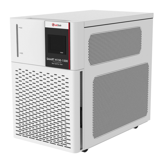
- Page 7 H50/150 Smart – User Manual SMART H150 CONTROL PANEL Touch controller H150 Series: Temperature Controller FRONT VIEW Liquid Level Indicator...
- Page 8 H50/150 Smart – User Manual REAR VIEW Fuse holder Pressure Regulation Valve Electrical Socket Liquid Return Connection Liquid Supply Connection Liquid Drain...
- Page 9 H50/150 Smart – User Manual SPECIFICATION Smart Smart Smart Smart Smart Smart Model H150-1000N H150-1000NLT H150-1500NS H150-2100NS H150-2100NSLT H150-3000NS 8 ~35 ℃ -20~35℃ 8 ~35 ℃ 8 ~35 ℃ -20~35℃ 8 ~35 ℃ Temp. control range Temp. control mode Cooling mode Compressor cooling Refrigerant R134A...
- Page 10 H50/150 Smart – User Manual MAGNETIC PRG & PR SERIES PUMP CAPACITY...
-
Page 11: Safety Rules
H50/150 Smart – User Manual 2. SAFETY RULES General Information Please read carefully this user manual before starting to use the instrument and follow its prescriptions with the utmost care. This user manual is part of the delivery, hence must be always kept together with the instrument on its working place. - Page 12 H50/150 Smart – User Manual Recommendation Never place the unit in a location where excessive heat, moisture, or corrosive materials are present. The unit construction provides extra protection against the risk of electrical shock by grounding appropriate metal parts. The extra protection may not function unless the power cord is connected to a properly grounded socket.
-
Page 13: Installation
H50/150 Smart – User Manual 3. INSTALLATION 3.1 POSITIONING THE INSTRUMENT The unit should be located in a clean environment where ambient temperature is between 10℃ and 35℃ (50℉ to 94℉). Max relative humidity: 80%, only indoor use, not for wet conditions. Max. -
Page 14: Electrical Requirements
H50/150 Smart – User Manual 3.2 ELECTRICAL REQUIREMENTS The unit provides extra protection against the risk of electrical shock by grounding appropriate metal parts. The extra protection may not function unless the power cord is connected to a properly grounded socket. It is the user’s responsibility to assure a proper ground connection is provided. -
Page 15: Fluids
H50/150 Smart – User Manual connections. Connect the ball valve to “DRAIN’’ position of the chiller and turn ball valve off. Never connect the fitting to the tap water supply or any water pressure source. It is important to keep the distance between the unit and the instrument to be cooled as short as possible. -
Page 16: Operation Procedure
H50/150 Smart – User Manual 4. OPERATION PROCEDURE 4.1 LCD CONTROLLER CHANGE SETPOINT Press SET to enter the temperature set interface, use buttons to decrease or increase the setpoint temperature. is a transposition key. Press SET again to save and quit the temperature set interface. -
Page 17: Touch Controller
H50/150 Smart – User Manual 4.2 TOUCH CONTROLLER 4.2.1 MAIN INTERFACE Heating Output Value Date and Time Cooling Output Value Running/Alarm status Settable Function Running Time Measurements Menu Settable Function a) Heating output indicator: the icon is switched ON when the unit is heating b) Cooling output indicator: the icon is switched ON when the unit is cooling c) Real time measurements: process parameters are shown on real time. -
Page 18: Main Menu
H50/150 Smart – User Manual 4.2.2 MAIN MENU a) HOME: touch HOME button to return to the MAIN INTERFACE WINDOW b) HELP: touch HELP button to show the USER MANUAL PARAMETER SETTING Return to Main Interface Page Switching Parameter Setpoint Parameter Range Numeric Keypad a) Page Switching: touch the area to change page under PARAMSET... - Page 19 H50/150 Smart – User Manual f) Parameters Setting Table NAME PARAMETER DESCRIPTION (RANGE) (-20.0~35.0°C) Temperature Setpoint Value of Temperature High temperature alarm (Active when the Temperature absolute (0.0~100.0°C) value Alarm is selected) Low temperature alarm (Active when (-20.0~HTL°C) the Temperature absolute value Alarm is selected) TAlarm...
-
Page 20: Alarms
Touch YES button to restore default parameters Cancel Factory Confirm Factory Resetting Resetting Note: always contact the LabTech Service Team for assistance before modifying or changing the factory setting. Any malfunction due to improper setting is not covered by the warranty. 4.2.3 ALARMS a). TEMPERATURE ALARM Temperature Over-range Alarm: alarm code “----”... - Page 21 H50/150 Smart – User Manual higher than High Limit Value Temperature (HTL) or lower than Low Limit Value Temperature (LTL), the buzzer alarm sounds and a warning alarm is shown to indicate overcooling or overheating. HTL and LTL can be set in the PARAMSET – TAlarm window.
-
Page 22: Start Up/Shut Down
Open the top panel of the water tank, remove its cap and fill it with water by using a funnel. For H50 series, it is better to exhaust the air in the pump before the first use, just put the supply tube in a container, switch on the unit for few seconds and leave flow out air and water. - Page 23 H50/150 Smart – User Manual The Pressure Relief Valve is used to adjust the unit’s fluid flow/pressure. NOTE: The valve is factory preset for the most common applications and normally requires no further adjustment. It is factory preset in order not to exceed 60 Psi (4.0Bar).
-
Page 24: Maintenance
H50/150 Smart – User Manual 5. MAINTENANCE 5.1 RESERVOIR CLEANING Periodically inspect the fluid inside the reservoir. If cleaning is necessary, flush the reservoir with a cleaning fluid compatible with the circulating system and the cooling fluid. The cooling fluid should be replaced periodically. Replacement frequency depends on the operating environment and running time. -
Page 25: Trouble Shooting
H50/150 Smart – User Manual 6. TROUBLE SHOOTING 6.1 UNIT DOES NOT START Check the cord; ensure it is plugged in. Check the position of the circuit breaker on the front of the unit. It has to be in the upper position. - Page 26 H50/150 Smart – User Manual 7. FLOW CHART...
- Page 27 H50/150 Smart – User Manual 8. SERVICE The LABTECH worldwide technical support network consists of highly trained Field Service Engineers, Technical Support Specialists and Service Coordinators who are ready to quickly assist customers with answers and solutions to service needs and application questions.
Need help?
Do you have a question about the H50 Series and is the answer not in the manual?
Questions and answers