
Subscribe to Our Youtube Channel
Related Manuals for nvent SCHROFF 11990-19 Series

Summary of Contents for nvent SCHROFF 11990-19 Series
- Page 1 14U 14-slot ATCA Shelf User Manual Product Number: 11990-190/192 October 2018 Doc-No: 63972-374_R1.0...
- Page 2 R1.0 October 2018 Initial Release Impressum: Schroff GmbH Langenalber Str. 96 - 100 75334 Straubenhardt, Germany The details in this manual have been carefully compiled and checked - supported by certified Quality Management System to EN ISO 9001/2000 The company cannot accept any liability for errors or misprints. The company reserves the right to amendments of technical...
-
Page 3: Table Of Contents
11990-190/192 Table of Contents Safety ............................ 1 Safety Symbols used in this document................1 General Safety Precautions ....................1 References and Architecture Specifications ..............2 Product definition ......................... 2 Terms and Acronyms ......................3 Hardware Platform ......................4 Shelf Front and Rear View....................5 ESD Wrist Strap Terminals.................... - Page 4 11990-190/192 6.7.4 Alarm Reset ......................21 6.7.5 Telco Alarm Connector (DB15-male).............. 22 RS-232 Serial Console Interfaces ..................23 Thermals..........................24 System Airflow Path 11990-190 ..................24 System Airflow Path 11990-192 ..................25 Front slot measurement zones..................26 Front Board Air Distribution ....................27 Rear Board Air Distribution ....................
-
Page 5: Safety
11990-190/192 1 Safety The intended audience of this User’s Manual is system integrators and hardware/software engineers. 1.1 Safety Symbols used in this document Hazardous voltage! This is the electrical hazard symbol. It indicates that there are dangerous voltages inside the Shelf. Caution! This is the user caution symbol. -
Page 6: References And Architecture Specifications
11990-190/192 1.3 References and Architecture Specifications • Pigeon Point Systems IPM Sentry Shelf-External Interface Reference (www.pigeonpoint.com) ® • PICMG 3.0 R3.0 AdvancedTCA® Base Specification (www.picmg.com) • AdvancedTCA base extensions specification PICMG-3.7 Revision-1.0 section 5 for the cooling aspects. • Intel specification: IPMI v2.0 •... -
Page 7: Terms And Acronyms
11990-190/192 1.5 Terms and Acronyms Table 1: Terms and Acronyms Term Definition ATCA Advanced Telecom Computing Architecture Backplane Passive circuit board providing the connectors for the front boards. Power distribution, management and auxiliary signal connections are supported Chassis Data Module Chassis Enclosure containing subrack, Backplane, boards, cooling devices, PEMs, same as Shelf Chassis Management Module, same as Shelf Manager... -
Page 8: Hardware Platform
11990-190/192 2 Hardware Platform • Mounting brackets for 19“ cabinets • ESD Wrist Strap Terminals at the front and the rear • 14 slot ATCA 40G/100G Backplane with Dual Star Fabric Interface, Dual Star Base Interface and bused IPMB interface, supporting twelve 8 U node board slots and two 8 U hub slots •... -
Page 9: Shelf Front And Rear View
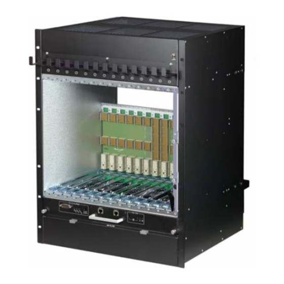
11990-190/192 2.1 Shelf Front and Rear View Figure 1: Shelf 11990-190 Front View Front Cable Tray Slot for Shelf Manger 1 ATCA 14-Slot Backplane Shelf Manager 2 Front Card Cage Serial Interfaces for the Shelf Managers Fan Tray 1 Air Filter Tray ESD Wrist Strap Terminal Hardware Platform R1.0, October 2018... - Page 10 11990-190/192 Figure 2: 11990-190 Shelf Rear View Fan Tray 2 Rear Cable Tray Rear Card Cage Power Entry Module A (PEM A) Power Entry Module B (PEM B) PEM Cover Hardware Platform R1.0, October 2018...
- Page 11 11990-190/192 Figure 3: Shelf 11990-192 Front View Front Cable Tray Slot for Shelf Manger 1 ATCA 14-Slot Backplane Shelf Manager 2 Front Card Cage Serial Interfaces for the Shelf Managers Fan Tray 1 Air Filter Tray ESD Wrist Strap Terminal Hardware Platform R1.0, October 2018...
-
Page 12: Esd Wrist Strap Terminals
11990-190/192 Figure 4: 11990-192 Shelf Rear View Fan Tray 2 Rear Cable Tray Rear Card Cage Power Entry Module A (PEM A) Power Entry Module B (PEM B) PEM Cover 2.2 ESD Wrist Strap Terminals Danger of electrostatic discharge! Static electricity can harm delicate components inside the Shelf. You must wear an ESD wrist strap before exchanging any part or electric component! Two ESD Wrist Strap Terminals (4 mm banana jacks) are located at the upper front and lower rear side of the Shelf. -
Page 13: Atca Backplane
11990-190/192 3 ATCA Backplane The 14-slot ATCA Backplane provides: • 40 Gb/s connectivity (4 lanes with 10 Gb/s) • 12 ATCA Node slots • Two ATCA Hub slots • Two dedicated Shelf Manager slots • Two Power Entry Module (PEM) slots •... -
Page 14: Backplane Overview
11990-190/192 3.1 Backplane Overview 3.2 Dedicated Shelf Manager Slots The front accessible Shelf Manager slots accept Schroff ShMM-ACB-VI Shelf Managers and are wired to: • IPMB-A and IPMB-B (I²C-bus) • Base Interface Channel 1 (ShMC) of the Base Interface Hub slots, support- ing Shelf Manager Cross Connect (10/100 Base T Ethernet) •... -
Page 15: Intelligent Platform Management Interface
11990-190/192 3.2.1 Intelligent Platform Management Interface The Shelf uses an Intelligent Platform Management Bus (IPMB) for management communications among all ATCA Boards and the Shelf Managers. The reliability of the IPMB is improved by the addition of a second IPMB, with the two IPMBs referenced as IPMB-A and IPMB-B. IPMB-A and IPMB-B are routed to the ATCA slots in a bused configuration. -
Page 16: Chassis Data Modules (Cdm)
11990-190/192 3.3 Chassis Data Modules (CDM) The Chassis Data Module (CDM) is a carrier board for the FRU SEEPROM (24LC256) Figure 6: Chassis Data Module 1 (CDM 1) 12712816 CDM 1 Connector PEM A Both CDMs are pluggable modules and located on the rear side of the ATCA Backplane. -
Page 17: Shelf Manager Cross Connect
11990-190/192 3.4 Shelf Manager Cross Connect The ATCA Backplane provides cross connect traces between the Base Hubs and the Shelf Managers according to PICMG Engineering Change Notice ECN 3.0-2.0-001. This ECN adds an option for dual 10/100 Base-T links from each Base Hub to both dedicated Shelf Manager slots. -
Page 18: Logic Ground (Gnd) And Shelf Ground (Shelf_Gnd)
11990-190/192 3.5 Logic Ground (GND) and Shelf Ground (Shelf_GND) Figure 8: Logic Ground/Shelf Ground Connection 12706816 The ATCA Backplane provides a mechanism to connect Logic Ground (GND) and Shelf Ground (Shelf_GND). You can connect/isolate Logic Ground by swapping two screws from position (A) to position (B). •... -
Page 19: Air Filter
11990-190/192 4 Air Filter Figure 9: Air Filter 12706958 Filter Element Filter Tray Handles Spring mounted ball lock 4.1 Introduction The ATCA Shelf provides a front replaceable air filter. The filter meets the requirements of the Telcordia Technologies Generic Requirements GR-78-CORE specification. 4.2 Air Filter Replacement/Maintenance The air filter tray can be removed by pulling the air filter's handle. -
Page 20: Shelf Ground Connection
11990-190/192 5 Shelf Ground Connection Hazardous voltage! Before powering-up the Shelf, make sure that the Shelf Ground terminal is connected to Protective Earth (PE) of the building. Please note, that in a typical telecom environment, the VRTN path of the -48 V supply is grounded to Protective Earth (PE) of the building. -
Page 21: Fan Trays
11990-190/192 6 Fan Trays 6.1 Introduction The Fan Trays are intelligent FRUs controlled by the ShMCs via IPMB. The ATCA Shelf contains two interchangeable Fan Trays arranged in a push- pull configuration for maximum air flow. The Fan Trays are plugged-in below and on top of the card cage. -
Page 22: Maintenance/Service
11990-190/192 Figure 11: Upper Fan Tray 11990-190 Figure 12: Upper Fan Tray 11990-192 Figure 13: Lower Fan Tray 12711836 6.2 Maintenance/Service We recommend a fan tray replacement every 4,5 years. Fan Trays R1.0, October 2018... -
Page 23: Fan Tray Block Diagram
11990-190/192 6.3 Fan Tray Block Diagram Figure 14: Fan Tray Block Diagram Only in lower Fan Tray Serial 1 Serial Console of Shelf Manager 1 protection Serial Console of Shelf Manager 2 Serial 2 protection Critical Alarm RS232 Major Alarm JTAG Minor Alarm NSEAT (Short Pin) -
Page 24: Fan Tray Signals
11990-190/192 6.4 Fan Tray Signals The Fan Tray provides signals for: • Voltage monitoring • Status of the Hot Swap Controller • Fan Speed • Temperature These signals are controlled by the IPM Controller devices on the Fan Tray PCB. The Shelf Manager has access to these signals via IPMB. 6.5 Fan Tray Temperature Sensor The temperature sensors (LM75) in the Fan Trays measure the input and exhaust temperatures of the Shelf. -
Page 25: Telco Alarms
11990-190/192 6.7 Telco Alarms 6.7.1 Telco Alarm Interface The lower Fan Tray provides a Telco Alarm interface on the DB15-male connector. Three relay outputs are used for remote alarm distribution, reflecting the state of the three Alarm LEDs. The relays are capable of carrying 72 VDC or 1 A with a max. -
Page 26: Telco Alarm Connector (Db15-Male)
11990-190/192 6.7.5 Telco Alarm Connector (DB15-male) Figure 15: Telco Alarm Connector (DB15-male) 12705896 Table 6: Telco Alarm Connector Pin Assignment Name Description AMIR+ MinorReset+ AMIR- MinorReset- AMAR+ MajorReset+ AMAR- MajorReset- ACNO CriticalAlarm - NO ACNC CriticalAlarm - NC ACCOM CriticalAlarm - COM AMINO MinorAlarm –... -
Page 27: Rs-232 Serial Console Interfaces
11990-190/192 6.8 RS-232 Serial Console Interfaces Figure 16: RS-232 Serial Console Interfaces 12710848 The lower Fan Tray provides two RS-232 serial console connectors for Shelf Manager 1 and 2. The connectors are 8-pin RJ45 modular receptacles. A full set of RS-232 signals, including modem control is provided. The serial interface is implemented on the ShMM-500. -
Page 28: Thermals
11990-190/192 7 Thermals The Schroff 14 slot ATCA Shelf provides airflow using two Fan Trays, one below the card cage and one above the card cage. Each Fan Tray has 6 fans moving air from the bottom to the top of the Shelf in a push-pull arrangement. This arrangement provides excellent airflow as well as fault tolerance in the unlikely event of a fan failure. -
Page 29: System Airflow Path 11990-192
11990-190/192 7.2 System Airflow Path 11990-192 Figure 18: System Airflow Path 12710877 Overall airflow = 2000 m³/h (1180 CFM) Front slot airflow = 113 m³/h (67 CFM) at the lowest performing slot Rear slot airflow = 16 m³/h (9 CFM) at the lowest performing slot (Air flow measured with CP-TA boards) Thermals R1.0, October 2018... -
Page 30: Front Slot Measurement Zones
11990-190/192 7.3 Front slot measurement zones Thermals R1.0, October 2018... -
Page 31: Front Board Air Distribution
11990-190/192 7.4 Front Board Air Distribution The airflow is measured with impedance boards acc. to the PICMG 3.0 R3.0 specification. • Front board pressure drop: 37 Pa at 0.85 m³/min Figure 19: Front Board Air Distribution 11990-190 Figure 20: Front Board Air Flow 11990-190 Thermals R1.0, October 2018... - Page 32 11990-190/192 Figure 21: Front Board Air Distribution 11990-192 Figure 22: Front Board Air Flow 11990-192 Thermals R1.0, October 2018...
-
Page 33: Rear Board Air Distribution
11990-190/192 7.5 Rear Board Air Distribution The airflow is measured with impedance boards acc. to the PICMG 3.0 R3.0 specification. • Rear board pressure drop: 24 Pa at 0.14 m³/min Figure 23: Rear Board Air Distribution 11990-190 Figure 24: Rear Board Air Flow 11990-190 Thermals R1.0, October 2018... - Page 34 11990-190/192 Figure 25: Rear Board Air Distribution 11990-192 Figure 26: Rear Board Air Flow 11990-192 Thermals R1.0, October 2018...
-
Page 35: Power Entry Module (Pem)
11990-190/192 8 Power Entry Module (PEM) Hazardous voltage! Before working ensure that the power is removed from the power connection cables. When the system is powered on, do NOT touch the power terminals. The Shelf can be powered using a regular telecommunication power supply of -48/-60 VDC with a VDC return. - Page 36 11990-190/192 through optical-isolation devices. The threshold for the blown fuse alarm is -29.5 VDC ±2 V. To indicate to the Shelf Manager the presence of the PEM, a presence signal is grounded by the PEM. A Hot Swap Push Button and a Blue Hot Swap LED provide Hot Swap functionality....
-
Page 37: Pem Front View
11990-190/192 8.2 PEM Front View Figure 27: PEM Front View PEM Cover Input Terminal Power Entry Module (PEM) R1.0, October 2018... -
Page 38: Specifications For The Power Cables
11990-190/192 8.3 Specifications for the Power Cables Caution! The wiring must be in compliance with local and national electrical codes and regulations. The PEM provides 4 M8 studs for the -48 V and the RTN feed to connect the power cables. - Page 39 11990-190/192 Figure 28: PEM Wiring Single cable wiring Feed B Feed A -48/-60 V -48/-60 V -48/-60 V -48/-60 V Split cable wiring Feed B Feed A -48/-60 V -48/-60 V -48/-60 V -48/-60 V Power Entry Module (PEM) R1.0, October 2018...
-
Page 40: Power Branches
11990-190/192 8.4 Power Branches The Backplane‘s power supply is divided into 6 power branches. Each of the PEM’s 6 power branches supplies power to a group of slots and a Fan or Shelf Manager. This topology is used to keep the max. current per branch less then 35 A. -
Page 41: Pem Block Diagram
11990-190/192 8.6 PEM Block Diagram Figure 30: PEM Block Diagram 12711845 Power Entry Module (PEM) R1.0, October 2018... -
Page 42: Pem Fuses
11990-190/192 8.7 PEM Fuses Figure 31: PEM Fuses 12714800 F101 Fuse Branch 1 (50 A/80 V) F401 Fuse Branch 4 (50 A/80 V) F201 Fuse Branch 2 (50 A/80 V) F501 Fuse Branch 5 (50 A/80 V) F301 Fuse Branch 3 (50 A/80 V) F601 Fuse Branch 6 (50 A/80 V) Power Entry Module (PEM) R1.0, October 2018... -
Page 43: Pem I²C-Bus Addresses
11990-190/192 8.8 PEM I²C-bus addresses Geographic address pins (HA0, HA1) on the PEM Backplane connector determine the I²C addresses of the devices. The I²C devices on the PEMs are connected to channel 4 of the Master-Only I²C-bus of the Shelf Managers. Table 8: PEM I²C-bus addresses PEM Location SEEPROM... -
Page 44: Shelf Management
11990-190/192 9 Shelf Management The Schroff ATCA Shelves are designed to work with two redundant Schroff Shelf Managers in dedicated Shelf Manager slots. Upon request is also a version with on-blade shelf management available. With on-blade shelf management, the I²C components of the PEMs and the SEEPROM of the CDMs are connected to the internal I²C bus on the Fan Trays. -
Page 45: Schroff Shelf Manager Acb-Vi
11990-190/192 9.1 Schroff Shelf Manager ACB-VI These Chapters describe the Shelf Manager hardware. For explicit software documentation see: • Pigeon Point Shelf Manager User Guide • Pigeon Point Shelf Manager External Interface Reference • Schroff Shelf Manager User‘s Manual, Order-no. 63972-243 The documentation is available for registered users at www.schroff.biz Shelf Manager with bused IPMB: 21990-401 (Product Number) 21990-404 (Catalog Number with packaging) - Page 46 11990-190/192 Figure 33: Schroff Shelf Manager 12708825 Extraction handle Backplane Connector (X100) ShMM-700R Backplane Connector (X102) RTC backup capacitor Fixing screw ACB-VI Carrier Board Shelf Management R1.0, October 2018...
-
Page 47: Front Panel Components
11990-190/192 9.2 Front Panel Components Figure 34: Shelf Manager Front Panel Components 12708844 Fixing screw RESET push button ETH 0 Ethernet Service Connector Shelf Manager Status LED (red) (RJ45) - Red = Out of Service (OOS) ETH 0 Link/Activity LED (yellow) Shelf Manager Status LED (green) - On = Link - Solid Green = in Service, active... -
Page 48: Bused Ipmb Interface
11990-190/192 9.3 Bused IPMB Interface The ShMM-700R provides two IPMBs. The IPMB-A and IPMB-B from the ShMM-700R are routed to the Backplane connector through I2c buffers. The ATCA Backplane buses the two IPMBs to the ATCA boards. The Active# signal of the ShMM-700R is used to switch on/off the pull-up resistors of the IPMBs. -
Page 49: Ethernet Interfaces
11990-190/192 9.4 Ethernet Interfaces The front panel ETH0 Ethernet connector is intended for service use only or for debugging purposes in laboratory environment. The computer which is connected to this interface must be located nearby the shelf manager with an Ethernet cable that is not longer than 10 m. - Page 50 11990-190/192 Figure 37: Shelf Manager Cross Connect 12709823 Table 10: Connector (P23) pin assignment for Shelf Manager Cross Connect Designation Shelf Manager Port Tx1+ Tx1- Rx1+ Rx1- Tx2+ Tx2- Rx2+ Rx2- with Shelf Manager Shelf Manager Cross Connect 1 Shelf Manager Cross Connect 2 Cross Connects Shelf Management R1.0, October 2018...
-
Page 51: Shelf Manager Rs-232 Console Serial Interface
11990-190/192 9.5 Shelf Manager RS-232 Console Serial Interface The Shelf Manager provides an RS-232 console interface that provides a full set of RS-232 signals, including modem control. These signals are routed through the Shelf Manager backplane connector to a RJ45 connector on the front panel of the lower Fan Tray. -
Page 52: Hot Swap Interface
11990-190/192 9.7 Hot Swap Interface The Shelf Manager provides a Hot Swap interface allowing the Shelf Manager to be replaced without powering down the Shelf. The interface is composed of three components: • Hot Swap switch at injector/ejector handle • Presence signal indicating that the Shelf Manager is fully seated in its backplane connector •... -
Page 53: Redundancy Control
11990-190/192 9.9 Redundancy Control The Shelf Manager supports redundant operation with automatic switchover using redundant Shelf Managers. In a configuration where two Shelf Manager are present, one acts as the active Shelf Manager and the other as a standby. The Shelf Managers monitor each other and either can trigger a switchover if necessary. -
Page 54: Command Line Interface (Cli)
11990-190/192 9.10 Command Line Interface (CLI) The Command Line Interface (CLI) connects to and communicates with the IPM-devices of the Shelf, the boards, and the Shelf Manager. The CLI is an IPMI-based library of commands, service personnel or system administrators can access the CLI through Telnet, SSH, or the Shelf Managers serial port on the SAP.... - Page 55 11990-190/192 • Display the FRU information in a board: clia fruinfo IPMI-address FRU-id • Change the speed for a Fan Tray: clia setfanlevel IPMI-address Fru-id speed Info: The value for the speed is from 0 to 15. • Display the contents of the System Event Log (SEL): clia sel •...
-
Page 56: Sensor Table
11990-190/192 9.11 Sensor Table Type- IPMC LUN Name Type Class Description Code FRU 0 HOT_SWAP Hot Swap 0xf0 Discrete This sensor returns the hot-swap states for FRU 0. IPMB LINK IPMB Link 0xf1 Discrete This sensor returns the IPMB link state. - Page 57 11990-190/192 Type- IPMC LUN Name Type Class Description Code I2C_PWR_B Voltage 0x02 Threshold This sensor measures the 3.3 V power supply B voltage supplied to I2C devices in volts. 5V0_local Voltage 0x02 Threshold This sensor measures the 5 V supply voltage for the ShMM700R on the local shelf manager in volts.
- Page 58 11990-190/192 Type- IPMC LUN Name Type Class Description Code TELCO Alarms OEM reserved 0xdf Discrete This sensor indicates the presence of critical, major and minor alarm. BMC Watchdog Watchdog 2 0x23 Discrete BMC watchdog sensor. SYSTEM EVENT System Event 0x12 Discrete System event sensor.
- Page 59 11990-190/192 Type- IPMC LUN Name Type Class Description Code PEM B Branch 1 Entity Presence 0x25 Discrete This sensor indicates the presence of the voltage after the fuse on branch 1 of PEM B. PEM B Branch 2 Entity Presence 0x25 Discrete This sensor indicates the presence of...
- Page 60 11990-190/192 Type- IPMC LUN Name Type Class Description Code -48V A Fused 1 OEM reserved 0xc0 Discrete This sensor indicates the presence of the –48 V_A branch 1 after fan tray’s main fuse. -48V A Branch 2 OEM reserved 0xc0 Discrete This sensor indicates the presence of the –48 V_A branch 2 at the lower fan...
- Page 61 11990-190/192 Type- IPMC LUN Name Type Class Description Code -48V A Fused 5 OEM reserved 0xc0 Discrete This sensor indicates the presence of the –48 V_A branch 5 after fan tray’s main fuse. -48V A Branch 6 OEM reserved 0xc0 Discrete This sensor indicates the presence of the –48 V_A branch 6 at the upper fan...
-
Page 62: Shelf Manager Front Panel And Backplane Connectors
11990-190/192 9.12 Shelf Manager Front Panel and Backplane connectors Table 12: Front Panel 10/100 Ethernet Service Connector Pin # Ethernet Signal 4, 5 n.c. 7, 8 n.c. Figure 38: Backplane Connectors Table 13: Pin Staging (PS) Pin# length 8.25 mm 9.75 mm 11.25 mm The Pin Staging (PS) is the length of the Pins of the connector at the Backplane... - Page 63 11990-190/192 Table 15: Backplane Signal Connector (X102) pin assignment (Bused IPMB) A UART0_TXD 1 FT0_PRES# UART1_TXD FT2_PRES# INT# A UART0_DTR 2 FT1_PRES# Pres_GND AUX_PRES# UART0_DSR A UART0_RTS 3 UART0_CD UART1_RXD UART0_CTS A I2C_SDA_CH1 4 UART0_RXD ACTIVE I2C_SDA_CH0 A I2C_SCL_CH0 5 I2C_SCL_CH1 UART0_RI I2C_SDA_CH3 A ETH0_TX-...
- Page 64 11990-190/192 Table 16: Backplane connector (J1) and (J2) pin description -48V_A -48 VDC supply A -48V_B -48 VDC supply B Air filter presence (grounded by air filter presence switch to detect a missing air AIR_FILT_PR filter) Serial Clock of IPMB-A, cross-connected on Backplane to serial clock of IPMB- CROSS_SCL_A B of other Shelf Manager Serial Clock of IPMB-B, cross-connected on Backplane to serial clock of IPMB-...
- Page 65 11990-190/192 I2C_SCL_CH4 Master-Only I C-bus Channel 4 I2C_SDA_CH0 Master Only-I C-bus Channel 0 to SAP I2C_SDA_CH1 Master-Only I C-bus Channel 1 I2C_SDA_CH2 Master-Only I C-bus Channel 2 I2C_SDA_CH3 Master-Only I C-bus Channel 3 I2C_SDA_CH4 Master-Only I C-bus Channel 4 IPMB_SCL_A_[1...16] Serial Clock, IPMB-A IPMB_SCL_B_[1...16] Serial Clock, IPMB-B...
-
Page 66: Technical Data
11990-190/192 10 Technical Data Table 17: Technical Data Physical Dimensions See drawing Weight Shelf weight completely assembled approx. 35 kg Power Input voltage -40 VDC …. -72 VDC Input Power 210 A per power feed (Each power feed is divided internally at the PEM in 6 out- put branches with 35 A each) Overcurrent Protection 50 A fuses on PEM... -
Page 67: Shelf Mechanical Dimensions
11990-190/192 10.1 Shelf Mechanical Dimensions Figure 39: Shelf dimensions All dimensions are in millimeters (mm). Technical Data R1.0, October 2018... - Page 68 11990-190/192 Technical Data R1.0, October 2018...
- Page 70 Schroff GmbH Langenalber Str. 96 - 100 75334 Straubenhardt, Germany +49.7082.794.0 +49.7082.794.200...
Need help?
Do you have a question about the SCHROFF 11990-19 Series and is the answer not in the manual?
Questions and answers