
Summary of Contents for Spectris Servomex OxyDetect
- Page 1 SERVOMEX OxyDetect OPERATOR MANUAL Part Number: 05311001B Revision: Language: UK English...
- Page 2 Servomex is a registered trademark of Servomex Group Limited. The use of all trademarks in this document is acknowledged. © 2016. Servomex Group Limited. A Spectris Company. All rights reserved. 05311001B / Revision 4...
-
Page 3: Table Of Contents
Contents OxyDetect Oxygen Deficiency Gas Detector CONTENTS Section Page DESCRIPTION AND DEFINITIONS ............1 Scope of this manual ................... 1 Safety information ..................1 Description ....................2 Ordering options ..................3 Certification ....................5 1.5.1 Hazardous area certification ..............5 Markings ..................... - Page 4 OxyDetect Oxygen Deficiency Gas Detector Contents 6.3.3 Changing passwords ................36 6.3.4 Adjusting the screen contrast ..............36 6.3.5 Adjusting the backlight timer ..............37 6.3.6 Setting the clock ................... 38 6.3.7 Changing regional settings ..............38 Configuring and using the mA outputs (option) ........... 39 6.4.1 Overview ....................
- Page 5 Contents OxyDetect Oxygen Deficiency Gas Detector A3.1 Introduction ....................67 A3.2 References ....................67 A3.3 Supported function codes ................67 A3.4 Exception codes ..................67 A3.5 Addressing ....................68 A3.6 Floating point numbers ................68 A3.7 System data mapping ................68 A3.8 Transducer data mapping ................
-
Page 6: Description And Definitions
OxyDetect Oxygen Deficiency Gas Detector 1 – Description and definitions 1 DESCRIPTION AND DEFINITIONS Scope of this manual This manual provides installation, operation and routine maintenance instructions for the 05311B1 OxyDetect - Oxygen Deficiency Fixed Gas Detector, abbreviated to "instrument" or “unit” in the remainder of this manual. Safety information Read this manual and ensure that you fully understand its content before you attempt to install, use or maintain the instrument. -
Page 7: Description
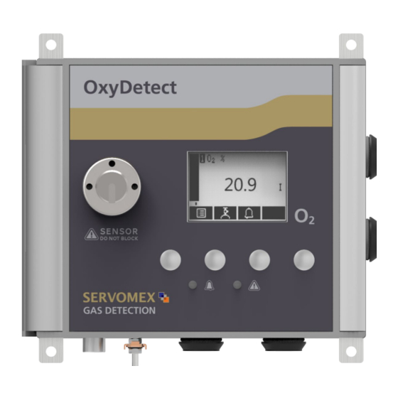
1 – Description and definitions OxyDetect Oxygen Deficiency Gas Detector Description The Instrument is a fixed wall mounted gas detector with an integral oxygen sensor that outputs a linear 4-20mA signal that represents an ambient oxygen concentration. Additionally, three changeover relays are provided to signal the following detector statuses. -
Page 8: Ordering Options
OxyDetect Oxygen Deficiency Gas Detector 1 – Description and definitions The safe area version is not to be used in certified or hazardous locations (potentially explosive atmospheres) La version de zone de sécurité ne doit pas être utilisé dans des endroits certifiés ou dangereux (atmosphères explosibles) The instrument is not suitable for corrosive atmospheres (those atmospheres where gases and vapours are present in... - Page 9 1 – Description and definitions OxyDetect Oxygen Deficiency Gas Detector Key Description Key Description 4 x mounting holes for M6 fixings Chassis earth Display Enclosure breather (do not block) 4 x Gland entries holes diameter Soft key 4, from left to right soft 22mm keys 1, 2, 3 and 4 Fault LED (amber)
-
Page 10: Certification
OxyDetect Oxygen Deficiency Gas Detector 1 – Description and definitions Certification 1.5.1 Hazardous area certification Do not modify the unit, either mechanically or electrically, as the certification of the instrument will be invalidated and it may not operate safely. Ne modifiez pas l'unité, soit mécaniquement ou électriquement, ou la certification de l'instrument sera invalidée et il ne peut pas fonctionner en toute sécurité. - Page 11 1 – Description and definitions OxyDetect Oxygen Deficiency Gas Detector K1: Relais de Carte Interface HM - Sealed Device K2: Relais de Carte Interface HM - Sealed Device K3: Relais de Carte Interface HM - Sealed Device EXPLOSION HAZARD - Substitution of components may impair suitability for CL I, Div 2.
-
Page 12: Markings
OxyDetect Oxygen Deficiency Gas Detector 1 – Description and definitions Only use a soft, clean cloth moistened with water to wipe clean the outside of the enclosure. Utilisez uniquement un chiffon doux et propre humidifié avec de l'eau pour nettoyer l'extérieur de l'enceinte. The equipment is incapable of passing the dielectric strength test prescribed by the standards, and so this must be taken into account during installation. -
Page 13: Label Locations
1 – Description and definitions OxyDetect Oxygen Deficiency Gas Detector 1.6.1 Label locations OxyDetect unit Certification label (fitted on hazardous location versions OxyDetect unit rating only. See Figure 4 & & serial number label Figure 5) (Figure 3) Figure 2 - OxyDetect unit label locations 05311001B / Revision 4... -
Page 14: Certification Information
OxyDetect Oxygen Deficiency Gas Detector 2 – Certification information 2 CERTIFICATION INFORMATION Hazardous area approval and certification 2.1.1 Equipment certification standards The standards to which the equipment has been certified are listed below: ATEX EN 60079-0:2012 + A11 :2013 EN 60079-7 :2015 EN 60079-11:2012 EN 60079-15:2010 IECEx... -
Page 15: North America
2 – Certification information OxyDetect Oxygen Deficiency Gas Detector 2.1.3 North America Coding Class I, Division 2, Groups A-D; T4 Class I, Zone 2, Group IIC; T4 Ambient Temperature -5 °C to +45 °C range SGS Contract No. 710216 SGS Certificate Reference SGSNA/19/SUW/00043 2.1.4 Label information Figure 3 - OxyDetect Rating Label... - Page 16 OxyDetect Oxygen Deficiency Gas Detector 2 – Certification information Figure 5 - OxyDetect North America CL1 Div 2 Certification label 05311001B / Revision 4...
-
Page 17: Specification
3 – Specification OxyDetect Oxygen Deficiency Gas Detector 3 SPECIFICATION The protection, accuracy, operation and condition of the equipment may be impaired if the instrument is not installed in accordance with the requirements of this and subsequent sections of the manual. La protection, la précision, le fonctionnement et l'état de l'équipement peut être altérée si l'instrument n'a pas été... - Page 18 The OxyDetect enclosure is designed such that it achieves IP66 ingress protection. However, operational consideration must be made for the protection of the sensor opening which is rated to IP40. Therefore, the instrument should not be exposed to washing with liquid jets. The instrument is for indoor use only.
-
Page 19: Unpack The Instrument
4 – Unpack the instrument OxyDetect Oxygen Deficiency Gas Detector 4 UNPACK THE INSTRUMENT The instrument is delicate and care must be taken when handling. L'instrument est délicate et il faut prendre soin lors de la manipulation. 1. Remove the instrument and any other equipment from its packaging. ... -
Page 20: Instrument User Interface
5 INSTRUMENT USER INTERFACE Introduction The instrument user interface comprises the following (shown on Figure 1): Display Shows various screens: see Section 5.2 onwards Soft keys The function of each of the soft keys depends on the screen currently being shown on the display: see Section 5.2 Alarm LED On when an alarm condition exists: see Section 6.5 Fault LED... -
Page 21: Soft Key Legends
5 – Instrument user interface OxyDetect Oxygen Deficiency Gas Detector During normal instrument operation, the software health indicator continuously moves from left to right and then back again, below the status icon bar. If the indicator stops moving, this means that the instrument is not operating correctly, and you must refer to Section 9. -
Page 22: System And Measurement Status Icons
Down Moves the cursor down a list (or decreases a digit during editing) Left Moves the cursor left Right Moves the cursor right System and measurement status icons System status is on the status icon bar and can be shown with a fault icon or a maintenance required icon, see table below. -
Page 23: The Menu Screen
5 – Instrument user interface OxyDetect Oxygen Deficiency Gas Detector As supplied, the security level is set to 'high', the supervisor password is set to "2000" and the operator password is set to "1000". The first time you try to access a password-protected option/screen, you will be prompted for the corresponding password. -
Page 24: The Settings Screen
Service Select this screen to calibrate [6.4.4]/check the mA outputs [8.2] & check status relay operation [8.3]. Status Select this screen to view active and historical fault and maintenance required messages [9.2]. Alternatively, press the soft key to display the measurement screen again. The settings screen Use the soft keys to highlight the required screen option, then... -
Page 25: The Information Screen
5 – Instrument user interface OxyDetect Oxygen Deficiency Gas Detector The information screen This screen shows information (such as the instrument serial number and the version of the operating software embedded in the instrument) which is useful to the Servomex support team. Figure 9 - Typical information screen Note that the information shown on the screen will vary, depending on the instrument model. - Page 26 Alternatively, use the soft keys to edit the data as follows: Soft key Function Increases the highlighted digit by 1 Decreases the highlighted digit by 1 Moves the cursor left to the previous digit Moves the cursor right to the next digit Note that the figures above and below the highlighted digit show the digits above and below the currently highlighted value.
-
Page 27: Installation And Set-Up
6 – Installation and set-up OxyDetect Oxygen Deficiency Gas Detector 6 INSTALLATION AND SET-UP The instrument must be installed by a suitably skilled and competent person. The following procedure must be followed to prevent a hazard. L'appareil doit être installé par un convenablement qualifiée et personne compétente. -
Page 28: Mechanical Installation
Mechanical installation Figure 11 - OxyDetect dimensions (in millimeters) Use 4 x M6 or similar fixings to secure the instrument to a suitably ridged wall or ridged mounting bracket. Leave access to either the side or bottom gland entry holes, which are 22mm in diameter. - Page 29 6 – Installation and set-up OxyDetect Oxygen Deficiency Gas Detector Ensure that the electrical installation of the instrument conforms with all applicable local and national electrical safety requirements. Assurez-vous que l'installation électrique de l'appareil est conforme à toutes les exigences locales et nationales applicables sécurité...
- Page 30 To meet IEC61010 the cables glands used with the 05311 OxyDetect Oxygen Monitor must: Be made of metal or have a flammability rating of V-1 or better. Be rated for temperatures from +5 °C to +45 °C (+41 °F to +113 °F).
-
Page 31: Electrical Data
6 – Installation and set-up OxyDetect Oxygen Deficiency Gas Detector métal ou en avoir un indice d'inflammabilité de V-1 ou mieux et maintenir le niveau IP40 de protection de l'environnement. 6.2.2 Electrical data Electrical supply Voltage 24 Vdc (10Vminimum; 28Vmaximum) Fuse rating / type T 2 A / 250 V size: 20 x 5 mm Maximum power consumption... - Page 32 The instrument allows configuration to 0-20mA. It is strongly recommended that the instrument is not configured to use the 0-20mA option when used in a safety related system, as the gas detection system in which the instrument is integrated must utilise the 0mA signal (Jam Low) of the 4-20mA signal as a measurement fault indication.
-
Page 33: Connect The Electrical Supply
6 – Installation and set-up OxyDetect Oxygen Deficiency Gas Detector TB3 – 3 x Signal interface relays (Alarm#1, Alarm#2 & Fault / O >23%) with protective insulation cover TB1 – Supply input TB2 – mA output U20 – TCPIP Modbus (Optional) Internal &... - Page 34 Ensure that your external electrical supply outlet is isolated and locked out before you connect the conductors in the electrical supply cable. Assurez-vous que votre prise d'alimentation électrique externe est isolé et verrouillé avant de connecter les conducteurs dans le câble d'alimentation électrique. Make sure that the dc power for the OxyDetect is not derived directly from an ac supply that is rated at more than 253 Vac.
-
Page 35: Analogue Output Connections
6 – Installation and set-up OxyDetect Oxygen Deficiency Gas Detector 1. Connect the wires in your cable to the screw terminals on TB1 see Figure 12. Terminal TB1-1 +24V dc TB1-2 0V dc Table 1 – Electrical supply connection TB1 dc power supply connection cable specifications Cable type Unscreened Number of cores required... - Page 36 To comply with EMC requirements, twisted pair screened cables must be used to connect the analogue outputs. Pour répondre aux exigences CEM, paire câbles blindés torsadés doivent être utilisés pour connecter les sorties analogiques. Connect the wires in your cable to the screw terminals on TB2 see Figure 12. Terminal TB2-1 Screen...
-
Page 37: Interface Relay Connections
6 – Installation and set-up OxyDetect Oxygen Deficiency Gas Detector 6.2.5 Interface Relay connections The terminals of all low voltage equipment connected to the OxyDetect by the user shall be separated from mains voltages by at least reinforced insulation. Les bornes de tous les équipements basse tension relié à la OxyDetect par l'utilisateur doivent être séparés des tensions d'alimentation par une isolation au moins renforcée. -
Page 38: Modbus Ethernet Connection (Option)
TB3 Relay output connection cable specifications Cable type Unscreened Number of cores required 2 to 6 cores as required Rating (temperature) +5 °C to +45 °C (+41 °F to +113 °F) Flammability rating VW-1 Approvals Relevant to local requirements Cable external diameter Within the range specified for the selected cable gland Conductors... -
Page 39: Switch On/Set-Up
6 – Installation and set-up OxyDetect Oxygen Deficiency Gas Detector The cable should not leave the building in which it is installed without suitable isolation. 2. The cable must be shielded CAT5E with standard RJ45 connectors. Switch on/set-up Ensure the instrument door is closed and screws tightened before the unit is powered. -
Page 40: Selecting The Security Level
The 'change the password(s)' and 'select the security level' screens/options are always protected by the supervisor password, regardless of the security level selected. This is to ensure that unauthorised personnel cannot change the security level and password(s) and so lock out the instrument from other users. -
Page 41: Changing Passwords
6 – Installation and set-up OxyDetect Oxygen Deficiency Gas Detector Once the supervisor password has been entered correctly, the security select screen will be displayed (see Figure 14), with the currently selected security level highlighted. Press the soft key twice to display the menus screen again. Figure 14 - The security select screen 6.3.3 Changing passwords If you change a password, ensure that you record the new password somewhere safe. -
Page 42: Adjusting The Backlight Timer
Figure 16 - The contrast screen Hold the soft key pressed in to adjust the contrast quickly. 6.3.5 Adjusting the backlight timer When the instrument is first switched on, the backlight goes on to illuminate the screen. If no soft key is pressed, the backlight will remain on for the pre-set 'backlight time', and will then go off. -
Page 43: Setting The Clock
6 – Installation and set-up OxyDetect Oxygen Deficiency Gas Detector 6.3.6 Setting the clock The time and date will remain set for approximately 1 week if the power supply to the instrument is switched off. After this period, it will be necessary to reset the date and time in order to clear the date/time invalid fault condition. -
Page 44: Configuring And Using The Ma Outputs (Option)
To change the regional settings: Settings Regional. Select This screen shows the first regional option (Language). Figure 20 - The regional settings (language) option screen Configuring and using the mA outputs (option) 6.4.1 Overview The instrument is supplied factory configured with a 4-20mA output scaled 0-25% for the gas measurement on both range 1 &... - Page 45 6 – Installation and set-up OxyDetect Oxygen Deficiency Gas Detector Parameter Values/options Range The selected option determines the mA output range associated with a measurement: Range 1 The output is set to use range 1 Range 2 The output is set to use range 2 To avoid accidental changes between range 1 and range 2 they should be set at the same levels.
-
Page 46: Setting Up The Ma Output Parameters
None The output values will continue to be derived from the sample gas measurements, even though these output values may be erroneous. mA output range 0 – 20 mA or 4 – 20 mA Underrange Any value below 4 mA Only available if the 4 –... - Page 47 6 – Installation and set-up OxyDetect Oxygen Deficiency Gas Detector Figure 23 - The mA output high level screen You can select the during calibration option to 'Freeze' or 'Follow'. Figure 24 - The during calibration screen You can then select the Jam condition to 'High', 'Low' or 'None'. Figure 25 - The jam condition screen You can then select the range that you would like to use: 0 –...
-
Page 48: Calibrating The Ma Output
Figure 27 - The mA under range screen 6.4.4 Calibrating the mA output Use the following procedure to calibrate the mA output: Service mA output. Select Figure 28 - The mA output service screen Select the required 'Calibrate' option. Figure 29 - The mA output calibrate screen 3. -
Page 49: Configuring The Measurement Alarms
6 – Installation and set-up OxyDetect Oxygen Deficiency Gas Detector Configuring the measurement alarms 6.5.1 Alarm modes and levels Two separate measurement alarms are available for the sample gas measurement, and you can configure each alarm to operate in one of three modes: Alarm mode Operation None... - Page 50 Set up. Select Select the required transducer and alarm. Figure 30 - The alarm set up screen Select the required mode (none, low or high), then press the soft key. Figure 31 - The alarm mode screen 4. Scroll up or down to edit the appropriate settings (using the method described in Section 5.10): ...
-
Page 51: Latching/Non-Latching Alarms
6 – Installation and set-up OxyDetect Oxygen Deficiency Gas Detector Select the correct option: "Yes" or "No". Figure 33 - The alarm follow options screen 6.5.2 Latching/non-latching alarms You can configure the measurement alarms to be either latching or not latching: ... -
Page 52: Viewing The Measurement Alarm Status
Alarm mode Effect of hysteresis Low alarm Once the low alarm condition has been activated, the alarm condition will not be deactivated until a sample measurement is above (alarm level + hysteresis level) High alarm Once the high alarm condition has been activated, the alarm condition will not be deactivated until a sample measurement is below (alarm level –... -
Page 53: Calibration
7 – Calibration OxyDetect Oxygen Deficiency Gas Detector 7 CALIBRATION During calibration it is good practice to perform a low (Lo) calibration followed by a high (Hi) calibration. Lors de l'étalonnage, il est de bonne pratique pour effectuer une (Lo) calibration bas suivi d'un étalonnage haute (Salut). It is recommended that calibration gas flow is monitored or routinely checked to ensure a representative sample is being supplied to the instrument. - Page 54 The calibration gases must be similar in temperature to the ambient temperature of the instrument. Gases taken from a cold or hot storage location should be allowed warm or cool prior to use. Les gaz d'étalonnage doivent être semblables à température ambiante à...
-
Page 55: Connecting The Calibration Gas Cap
7 – Calibration OxyDetect Oxygen Deficiency Gas Detector Connecting the calibration gas cap Low calibration gases are asphyxiants: Ensure that the instrument is used in a sufficiently well-ventilated environment, to prevent the build-up of asphyxiant gas. Ensure that the pipes that you connect to the instrument are routed so that they do not present a hazard to people. -
Page 56: Manual Calibration
Figure 35 - Calibration gas cap connection The instrument is supplied with a calibration cap and tube. Push one end of the tube onto the calibration cap and connect the other end onto a suitable supply of calibration gas. Calibration gas cylinders are available from Servomex. - Page 57 7 – Calibration OxyDetect Oxygen Deficiency Gas Detector Calibrate. 2. Select Figure 36 - The calibrate screen Note that the "9999d" field of the screen shown in Figure 36 will identify the period of time that has elapsed since the last calibration, and can be in any of the following forms: ...
-
Page 58: Routine Maintenance
8 ROUTINE MAINTENANCE Inspecting the calibration cap Before each use inspect the calibration cap and its internal o-ring for signs of wear or damage. Check that the hose connection is tight and that all parts are clean. If necessary purchase a new calibration cap from Servomex or your Servomex agent. Checking the mA output If required, use the following procedure at any time to perform a check on a mA output:... -
Page 59: Cleaning The Instrument
8 – Routine maintenance OxyDetect Oxygen Deficiency Gas Detector Figure 39 - The relay override state screen When a relay is energised, the N/C-Common contacts will be open, and the N/O-Common contacts will be closed. The converse is true when the relay is de-energised. - Page 60 factory specification. Once inspection and repair are complete, you will be provided with a full SERVOSURE report. Note that you will always be informed in advance if any repairs or new parts are required for your instrument. Contact Servomex or your local Servomex agent to arrange for a preventative maintenance contract.
-
Page 61: Fault Finding
9 – Fault finding OxyDetect Oxygen Deficiency Gas Detector 9 FAULT FINDING Fault, maintenance required and SIP statuses 9.1.1 Status definitions The status definitions are as follows: Fault – A serious fault has been detected. Maintenance required – A maintenance required status has been raised, the instrument requires attention. - Page 62 Message Measurement Recommended actions screen icon Database fault Turn the instrument off, and then turn it on again. If the fault message is then displayed again, contact Servomex or your local Servomex agent for assistance. Date/Time invalid This usually occurs because the electrical supply to the instrument has been switched off for more than a week.
-
Page 63: Viewing Messages
9 – Fault finding OxyDetect Oxygen Deficiency Gas Detector Message Measurement Recommended actions screen icon Transducer error Ensure that you are using the instrument in the specified operating conditions (refer to Section 3). If the fault persists, contact Servomex or your local Servomex agent for assistance. -
Page 64: View History Messages
9.2.2 View history messages Status View history. Select Each message shows: Date and time of message. The message type ("Fault", "Maintenance rqd" or "Service in Progress"). The message itself. The status of the entry "ON" or "OFF". Figure 42 - The message status screen Refer to Section 9.1 for the recommended actions associated with the displayed messages. - Page 65 9 – Fault finding OxyDetect Oxygen Deficiency Gas Detector Fault symptom Recommended actions The software health indicator is not Carry out the recommended actions for the "The moving on the display. fault LED is on" symptom above. " - - - - - " is displayed instead of a This indicates a possible measurement error, or a sample measurement.
- Page 66 Fault symptom Recommended actions The measurement alarms are Check that the instrument is not being knocked, activating more often than moved, or subjected to high levels of vibration expected. during sample measurements. Check that the alarm modes, alarm levels and hysteresis levels have been correctly set: refer to Section 6.5.
-
Page 67: Storage And Disposal
10 – Storage and disposal OxyDetect Oxygen Deficiency Gas Detector 10 STORAGE AND DISPOSAL 10.1 Storage Refit any protective plastic covers and place the instrument and any associated equipment in its original packaging before storage. Alternatively, seal it inside a waterproof plastic bag, sack, or storage box. -
Page 68: Spares
OxyDetect Oxygen Deficiency Gas Detector Appendix 11 SPARES Do not use spares other than those specified below, and do not attempt to carry out any maintenance procedures other than those specified in this manual. If you do, you can damage the instrument and invalidate any warranty. -
Page 69: Disposal In Accordance With The Waste Electrical And Electronic Equipment (Weee) Directive
Appendix OxyDetect Oxygen Deficiency Gas Detector 12 DISPOSAL IN ACCORDANCE WITH THE WASTE ELECTRICAL AND ELECTRONIC EQUIPMENT (WEEE) DIRECTIVE The label shown in Figure A1 is fitted to the analyser. Figure A1 – The WEEE label This label identifies that: ... -
Page 70: Appendix
OxyDetect Oxygen Deficiency Gas Detector Appendix 13 APPENDIX PERFORMANCE DATA Performance data has been determined in accordance with EN61207. Display indication Measurement range limits 0 to 25% O (Safe area installations) 0 to 21% O (Hazardous area installations) Intrinsic error (accuracy) <±... -
Page 71: A2 Factory Configuration Settings
Appendix OxyDetect Oxygen Deficiency Gas Detector Factory Configuration settings The OxyDetect is factory configured with parameters typical for an oxygen deficiency detector (measurement alarms 1 & 2 and the mA output). The end user is able to adjust these settings to suit the specific requirements of the gas alarm system as detailed in section 6. -
Page 72: Implementation Guide For Modbus Ethernet Communications (Option)
IMPLEMENTATION GUIDE FOR MODBUS ETHERNET COMMUNICATIONS (OPTION) A3.1 Introduction This appendix details the implementation and use of the Modbus protocol in the Servomex OxyDetect. A3.2 References Document "MODBUS over Serial Line Specification & Implementation guide V1.0 Nov 02" Modbus web site modbus.org. -
Page 73: A3.5 Addressing
Appendix OxyDetect Oxygen Deficiency Gas Detector This does NOT mean that a value to be stored in a register is incorrect as Modbus has no means of determining what is legal for any particular register. Slave device failure An unrecoverable error occurred while the unit was attempting to perform the requested action. - Page 74 OxyDetect Oxygen Deficiency Gas Detector Appendix Register Name Comments 5001 – 5002 Transducer 1 Floating point number A block of 100 registers is allocated for the transducer to provide the means of supplying the measurement and other transducer related data as follows: Register Name Comments...
-
Page 75: System Fault Mapping
Appendix OxyDetect Oxygen Deficiency Gas Detector A3.9 System Fault Mapping Read-only access to system fault information will be provided in a block of 100 registers. These can be accessed as discrete inputs using function code 02 or as input registers using function code 04. Reading them as discrete inputs provides a simple bit result for each, 0 for off and 1 for on. -
Page 76: A3.10 Transducer Fault And Alarm Mapping
OxyDetect Oxygen Deficiency Gas Detector Appendix A3.10 Transducer fault and alarm mapping Read-only access to transducer fault and alarm information will be provided in a block of 100 registers and coils. These can be accessed as discrete inputs using function code 02 or as input registers using function code 04. - Page 77 Appendix OxyDetect Oxygen Deficiency Gas Detector Register Name Comments 1113 Incorrect transducer type Incorrect type of transducer fitted. 1114 Transducer not detected Transducer is unplugged or broken. 1115 Low calibration fail Auto cal low failed. 1116 High calibration fail Auto cal high failed. 1117 Low validation fail Auto val low failed.
-
Page 78: A3.11 System Set-Up Mapping
OxyDetect Oxygen Deficiency Gas Detector Appendix Register Name Comments 1138 Auto validation/calibration. Sequence is in progress. 1139 mA service in progress Calibration or override in progress. 1140 Volt service in progress Calibration or override in progress. 1141 Pressure service in progress Calibration in progress. 1142 Relay service in progress Override in progress. -
Page 79: A3.12 Transducer Set-Up Mapping
Appendix OxyDetect Oxygen Deficiency Gas Detector A3.12 Transducer set-up mapping Each transducer will provide read-write access to various set-up data in blocks of holding registers that can be read with function code 03 and written with function codes 06 and 16. Each register provides 2 bytes of data so it takes 2 registers each to store a 4 byte floating point measurement value. -
Page 80: A3.13 System Control
OxyDetect Oxygen Deficiency Gas Detector Appendix Register Name Comments 147 – 148 Alarm 1 level Float. 149 – 150 Alarm 1 hysteresis Float. Alarm 2 mode 0 = none, 1 = low, 2 = high. Alarm 2 latching 0 = no, 1 = yes. 153 –... - Page 81 Appendix OxyDetect Oxygen Deficiency Gas Detector The coils for transducer 1 are shown in the following table: Coil Name Comments Measurement Calibration mode on/off 0 = off (normal), 1 = on (alarms masked, jamming etc). Write 1 to turn calibration mode on. Low calibration gas 0 = sample gas, 1 = low calibration gas.
-
Page 82: A4 Configuring The Modbus Parameters (Option)
OxyDetect Oxygen Deficiency Gas Detector Appendix CONFIGURING THE MODBUS PARAMETERS (OPTION) If your analyser has the Modbus Ethernet output, you must configure the communications parameters to suit the requirements of the network to which you have connected the analyser. The cable connections are shown in Section 6.2. ... - Page 83 Appendix OxyDetect Oxygen Deficiency Gas Detector Use the soft keys to select the next parameter: 6. Gateway address, or router, allows communication other segments. The gateway address should be the IP address of the router Figure A4 – Comms parameters connected to the same LAN segment gateway address screen - example as the unit.
-
Page 84: A5 Cross Interference Offsets
OxyDetect Oxygen Deficiency Gas Detector Appendix CROSS INTERFERENCE OFFSETS For a paramagnetic oxygen measurement, the composition of any typical background gas in the gas sample will have a small effect on the analyser oxygen measurement. The following table gives 4 examples of cross-interference errors (O measurement errors) in atmospheres which contain 100% of a specific background gas, for an analyser which has been 'Lo' calibrated with N... - Page 85 Appendix OxyDetect Oxygen Deficiency Gas Detector A full list of cross-interference offsets (O measurement errors) are given in Appendix A5. For the OxyDetect the offset should be taken from the 20 °C. Pure Gas Formula Molar Cross interference offsets mag.susc Ambient Temperature x 10...
- Page 86 OxyDetect Oxygen Deficiency Gas Detector Appendix Pure Gas Formula Molar Cross interference offsets mag.susc Ambient Temperature x 10 20 °C 50 °C Enflurane (Ethrane) –80.10 –1.97 –2.17 Ethane –26.80 –0.43 –0.47 Ethanol –33.60 –0.62 –0.69 Ethyl acetate COOC –54.20 –1.22 –1.34 Ethyl amine –39.90...
- Page 87 Appendix OxyDetect Oxygen Deficiency Gas Detector Pure Gas Formula Molar Cross interference offsets mag.susc Ambient Temperature x 10 20 °C 50 °C Neon –6.70 0.15 0.17 Nitric oxide 1461.00 42.56 42.96 Nitrobenzene –61.80 –1.44 –1.59 Nitrogen –12.00 0.00 0.00 Nitrogen dioxide 150.00 5.00 16.00...
-
Page 88: A6 End User Notes
OxyDetect Oxygen Deficiency Gas Detector Appendix End User Notes 05311001B / Revision 4...
Need help?
Do you have a question about the Servomex OxyDetect and is the answer not in the manual?
Questions and answers