Table of Contents
Advertisement
Quick Links
General Information
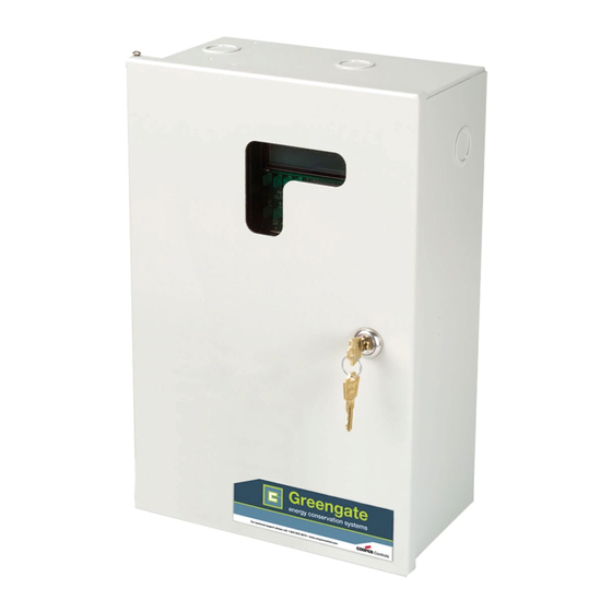
The LiteKeeper-8
is shipped in one package. The relay card
®
is mounted in the high voltage compartment. The logic board
and inputs are located in the low voltage compartment. The
following information describes the LiteKeeper
For programming information, refer to the LiteKeeper
gramming Manual.
Getting Started
1. Do not discard these installation instructions. Please keep
for future reference and operation information.
2. The relay cards are protected by shrink-wrap. Leave
shrink-wrap in place until all drilling and metal work is com-
plete to protect against metal shards getting into compo-
nent circuitry.
3. Always disconnect all power before wiring.
4. Use only as intended and at the listed voltage.
5. All installation service must be performed by qualified
personnel or service technicians.
6. Install in accordance with National Electrical Code and
any other codes that may apply.
7. High Voltage is present inside the lighting enclosure.
Use extreme caution when performing maintenance on
this equipment. Failure to follow this warning and proper
safety procedures could result in severe injury or death
and/or damage to the equipment.
8. Document all wiring that is terminated to the relays so that
the lighting control equipment can be properly configured
and programmed for operation.
9. It is recommended that all low voltage wiring be done with
power removed to the logic board to protect components
from potential shorts during the wiring process.
Mounting the Enclosure
1. Choose a dry location convenient to the circuit breaker
panel.
2. Mount the panel on a firm surface using predrilled
holes.
3. Connect the enclosure to the circuit breaker panel using
conduit into the punch holes provided.
4. Remove all cuttings and dirt before removing shrink-wrap
from the relays.
Cooper Controls
Cooper Controls
203 Cooper Circle, Peachtree, GA 30269
203 Cooper Circle, Peachtree, GA 30269
800-553-3879
800-553-3879
www.coopercontrol.com
www.coopercontrol.com
LiteKeeper-8
Note: Make certain that high voltage and low voltage wiring
enters the enclosure separately. High Voltage wiring should
be brought into the top or bottom of the enclosure. Low Volt-
installation.
age wire should enter in the low voltage wiring compartment
®
Pro-
on the left side of the enclosure.
®
Failure to separate high voltage from low voltage wiring may
cause interference with logic board function.
Low Voltage Wiring Compartment
Wiring the Transformer
The transformer is multi-tapped and voltages are color-coded.
The transformer is available in 120/277VAC and 120/347VAC
models. It is recommended that a dedicated branch circuit
with circuit protection be provided for the transformer.
1. Connect neutral wire to the wire with the appropri-
ate color-coding for the voltage being used: White/
Black=120VAC,White/Orange=277VAC, Brown=347VAC.
2. Connect the solid black wire to the dedicated branch circuit
that is powering the transformer.
®
ON
C
H
+24
1
LITEKEEPER
OFF
12:OO O1/O1/95
ON
C
H
+24
1
OFF
1
3
5
7
1
2
3
A
RELAY
ON
OUTPUTS
C
2
4
6
8
H
+24
4
5
6
B
1
OFF
ON
7
8
9
C
C
H
+24
1
*
0
#
D
OFF
ON
C
H
+24
1
OFF
ON
C
H
+24
1
OFF
ON
C
H
+24
1
OFF
ON
C
H
+24
8
OFF
+24
VDC
DC
GND
Low/High Voltage
System Power Supply
Line voltage = black
Neutral:
120VAC = white/black
277VAC = white/orange
347VAC = brown
Ground = green
Transformer Wiring Information
InstAllAtIon sheet
Model#
lK8-no
Model#
lK8-lRC
Model#
lK8-MRC
Model#
lK8-tPRC
High Voltage Wiring Compartment
Advertisement
Table of Contents

Subscribe to Our Youtube Channel
Summary of Contents for Cooper Controls Greengate LiteKeeper-8
- Page 1 Ground = green 4. Remove all cuttings and dirt before removing shrink-wrap from the relays. Transformer Wiring Information Cooper Controls Cooper Controls 203 Cooper Circle, Peachtree, GA 30269 203 Cooper Circle, Peachtree, GA 30269 800-553-3879 800-553-3879 www.coopercontrol.com...
- Page 2 Connecting Relay Loads Latching Relay Card Notes The relay cards will be pre-mounted by the manufacturer in 1. The Latching Relay Card is rated for single-pole load use the enclosure per the order specifications. There are currently only. Connection of 2 pole circuits/loads to the Latching four available relay types for the enclosure.
- Page 3 3. Tighten down relay terminal screws. Manufacturer’s recom- mended torque rating is 7 lbs-in. (0.59 lbs-foot) (0.8 Nm). Modular Relay Card Wiring Diagram 4. Document relay to circuit information for future reference. Line Load Latching Relay Module Relay Rating: 20Amps 120/277/347 VAC Wire: 6 AWG max.
- Page 4 Two Pole Relay Card Notes 3. Tighten down relay terminal screws. Manufacturer’s recom- mended torque rating is 18lb-in. (1.475 foot-lbs) (2.0 Nm). The Two Pole Relay Card(s) is installed at the factory in the 4. Document relay to circuit information for future reference. Lighting Controller specified.
- Page 5 Connecting Low Voltage Inputs The LiteKeeper-8 logic board can support up to 64 switch ® inputs. Of these 64 inputs, 8 of them may be dry contact clo- +24VDC sure inputs that are connected to the terminal blocks on the left side of the LiteKeeper Logic Board.
- Page 6 Digital Switch Wiring Each LiteKeeper-8 unit is capable of supporting the Green- ® gate Digital Switch (GDS) station. The GDS do not wire directly to the LiteKeeper-8 logic board, but are wired using a CAN ® Bus network that connects to the LiteKeeper -8 through a ®...
- Page 7 Clear Settings Command: A clear settings command is used to remove all programming from a LiteKeeper-8 unit. ® It should be done before programming to the unit for the first time or when asked to by a Technical Support representative. Please use caution with this command! When performing a Clear command, all relay loads will turn off.
- Page 8 All products manufactured by Cooper Controls and identified with the Greengate brand are warranted to be free from defects in material and work- manship and shall conform to and perform in accordance with seller’s written specifications for a period of : • Five (5) years from date of shipment for all occupancy sensors.
Need help?
Do you have a question about the Greengate LiteKeeper-8 and is the answer not in the manual?
Questions and answers